2003 CHRYSLER CARAVAN lock
[x] Cancel search: lockPage 1558 of 2177
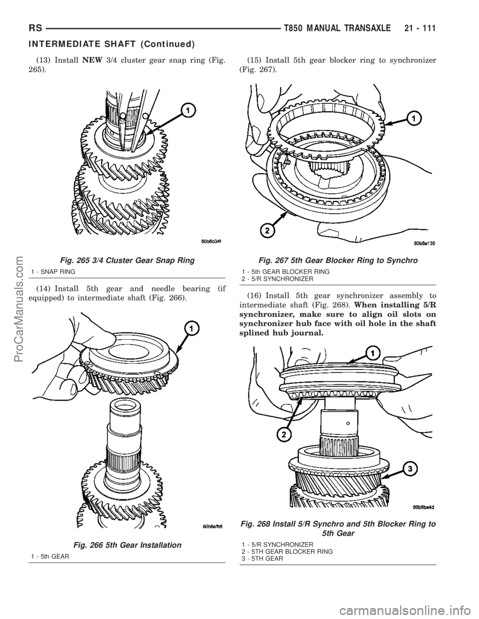
(13) InstallNEW3/4 cluster gear snap ring (Fig.
265).
(14) Install 5th gear and needle bearing (if
equipped) to intermediate shaft (Fig. 266).(15) Install 5th gear blocker ring to synchronizer
(Fig. 267).
(16) Install 5th gear synchronizer assembly to
intermediate shaft (Fig. 268).When installing 5/R
synchronizer, make sure to align oil slots on
synchronizer hub face with oil hole in the shaft
splined hub journal.
Fig. 265 3/4 Cluster Gear Snap Ring
1 - SNAP RING
Fig. 266 5th Gear Installation
1 - 5th GEAR
Fig. 267 5th Gear Blocker Ring to Synchro
1 - 5th GEAR BLOCKER RING
2 - 5/R SYNCHRONIZER
Fig. 268 Install 5/R Synchro and 5th Blocker Ring to
5th Gear
1 - 5/R SYNCHRONIZER
2 - 5TH GEAR BLOCKER RING
3 - 5TH GEAR
RST850 MANUAL TRANSAXLE21 - 111
INTERMEDIATE SHAFT (Continued)
ProCarManuals.com
Page 1559 of 2177
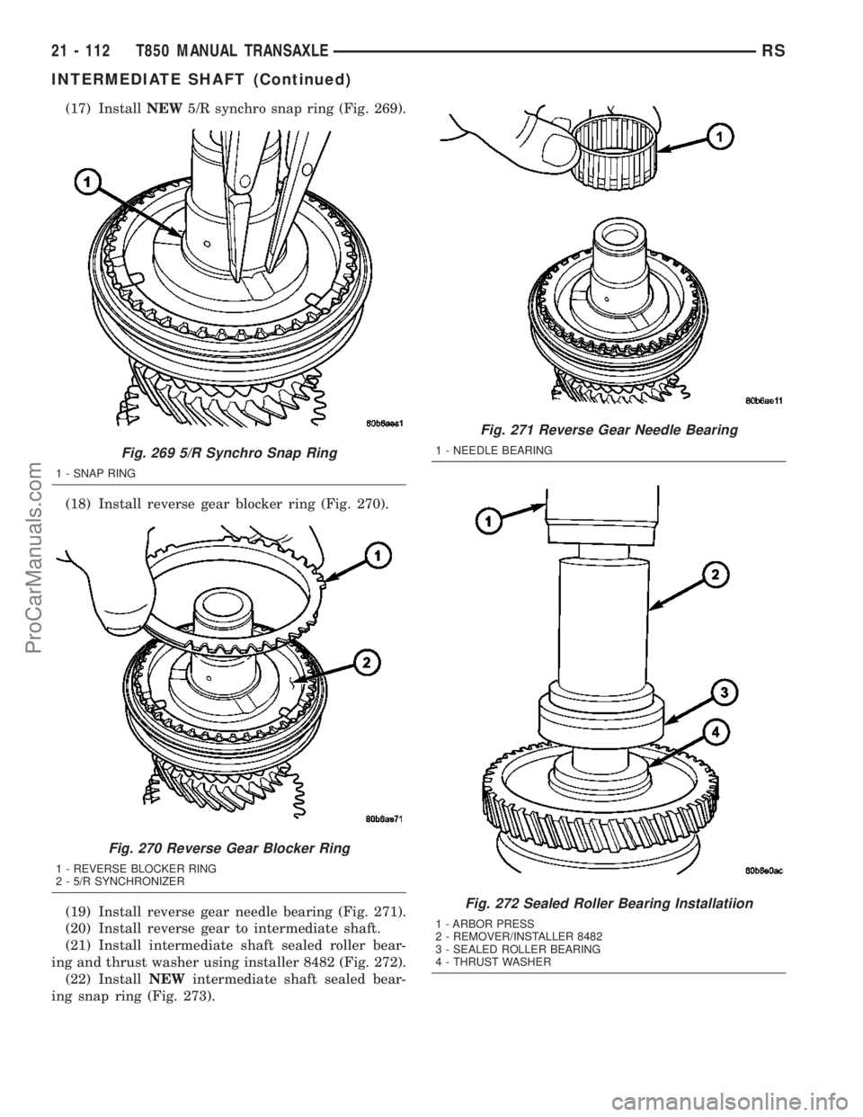
(17) InstallNEW5/R synchro snap ring (Fig. 269).
(18) Install reverse gear blocker ring (Fig. 270).
(19) Install reverse gear needle bearing (Fig. 271).
(20) Install reverse gear to intermediate shaft.
(21) Install intermediate shaft sealed roller bear-
ing and thrust washer using installer 8482 (Fig. 272).
(22) InstallNEWintermediate shaft sealed bear-
ing snap ring (Fig. 273).
Fig. 269 5/R Synchro Snap Ring
1 - SNAP RING
Fig. 270 Reverse Gear Blocker Ring
1 - REVERSE BLOCKER RING
2 - 5/R SYNCHRONIZER
Fig. 271 Reverse Gear Needle Bearing
1 - NEEDLE BEARING
Fig. 272 Sealed Roller Bearing Installatiion
1 - ARBOR PRESS
2 - REMOVER/INSTALLER 8482
3 - SEALED ROLLER BEARING
4 - THRUST WASHER
21 - 112 T850 MANUAL TRANSAXLERS
INTERMEDIATE SHAFT (Continued)
ProCarManuals.com
Page 1560 of 2177
SHIFT COVER
DESCRIPTION
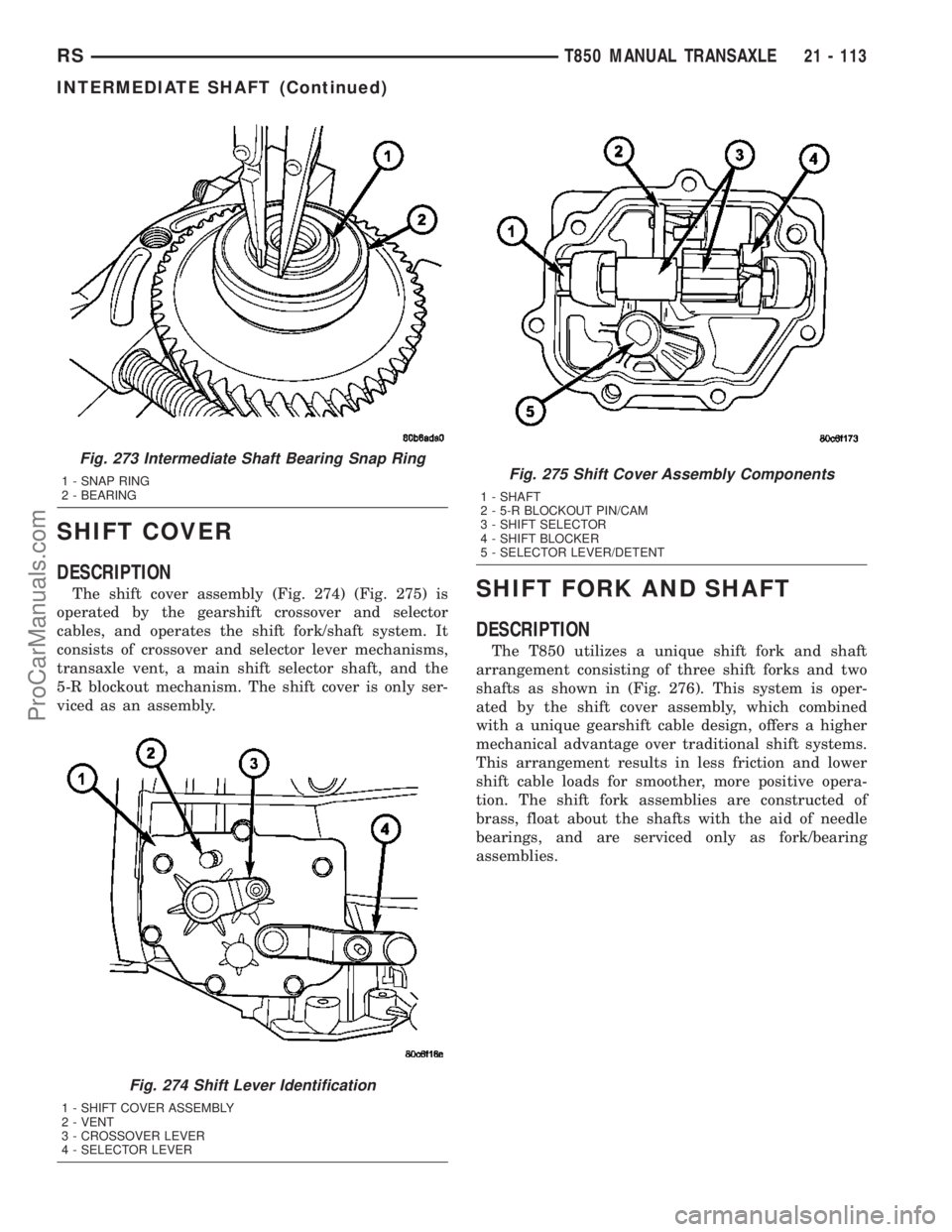
The shift cover assembly (Fig. 274) (Fig. 275) is
operated by the gearshift crossover and selector
cables, and operates the shift fork/shaft system. It
consists of crossover and selector lever mechanisms,
transaxle vent, a main shift selector shaft, and the
5-R blockout mechanism. The shift cover is only ser-
viced as an assembly.SHIFT FORK AND SHAFT
DESCRIPTION
The T850 utilizes a unique shift fork and shaft
arrangement consisting of three shift forks and two
shafts as shown in (Fig. 276). This system is oper-
ated by the shift cover assembly, which combined
with a unique gearshift cable design, offers a higher
mechanical advantage over traditional shift systems.
This arrangement results in less friction and lower
shift cable loads for smoother, more positive opera-
tion. The shift fork assemblies are constructed of
brass, float about the shafts with the aid of needle
bearings, and are serviced only as fork/bearing
assemblies.
Fig. 273 Intermediate Shaft Bearing Snap Ring
1 - SNAP RING
2 - BEARING
Fig. 274 Shift Lever Identification
1 - SHIFT COVER ASSEMBLY
2 - VENT
3 - CROSSOVER LEVER
4 - SELECTOR LEVER
Fig. 275 Shift Cover Assembly Components
1 - SHAFT
2 - 5-R BLOCKOUT PIN/CAM
3 - SHIFT SELECTOR
4 - SHIFT BLOCKER
5 - SELECTOR LEVER/DETENT
RST850 MANUAL TRANSAXLE21 - 113
INTERMEDIATE SHAFT (Continued)
ProCarManuals.com
Page 1561 of 2177
SYNCHRONIZER
DESCRIPTION
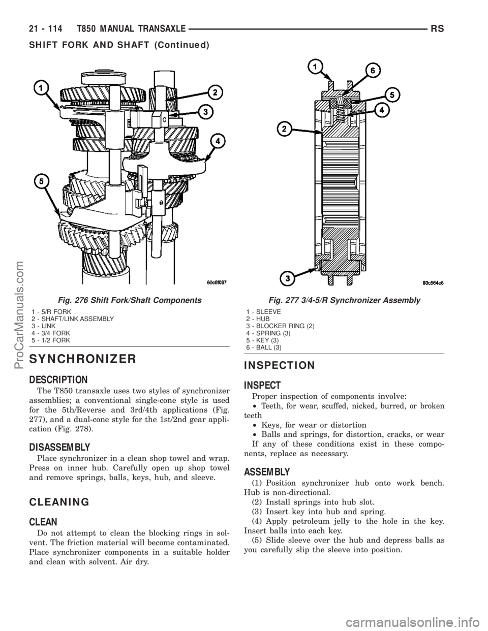
The T850 transaxle uses two styles of synchronizer
assemblies; a conventional single-cone style is used
for the 5th/Reverse and 3rd/4th applications (Fig.
277), and a dual-cone style for the 1st/2nd gear appli-
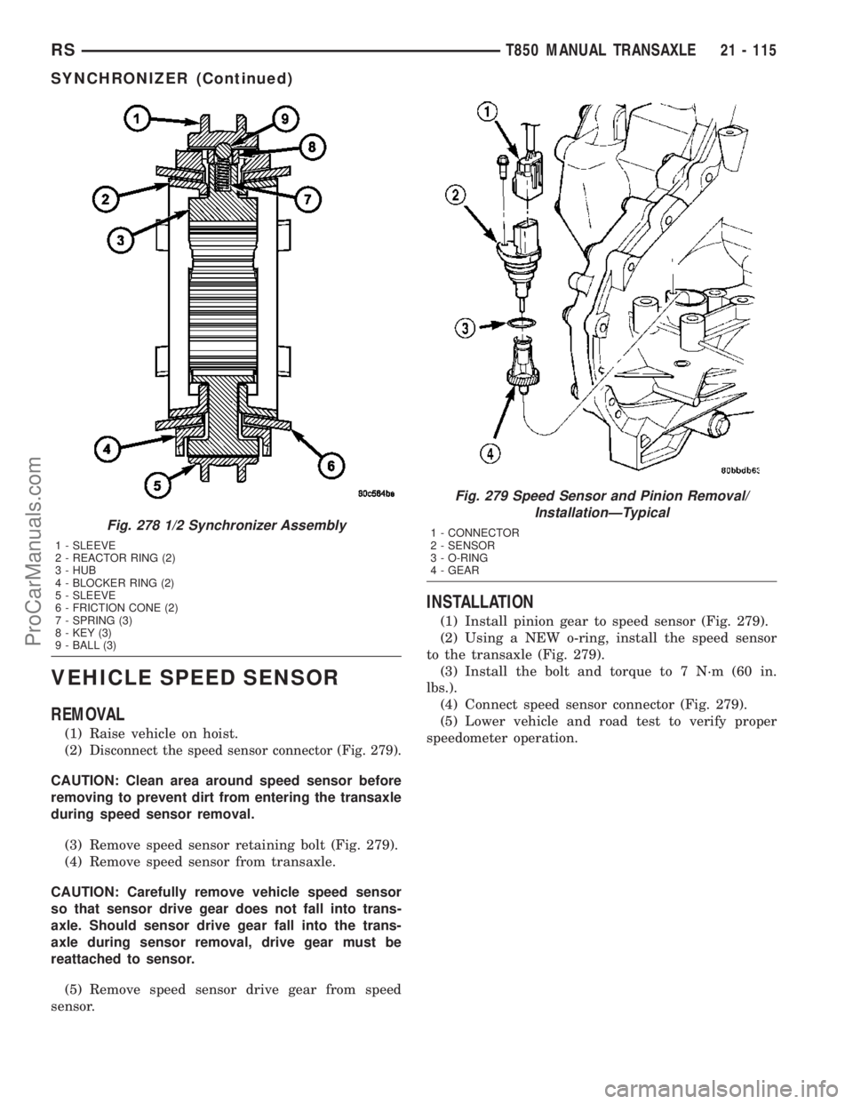
cation (Fig. 278).
DISASSEMBLY
Place synchronizer in a clean shop towel and wrap.
Press on inner hub. Carefully open up shop towel
and remove springs, balls, keys, hub, and sleeve.
CLEANING
CLEAN
Do not attempt to clean the blocking rings in sol-
vent. The friction material will become contaminated.
Place synchronizer components in a suitable holder
and clean with solvent. Air dry.
INSPECTION
INSPECT
Proper inspection of components involve:
²
Teeth, for wear, scuffed, nicked, burred, or broken
teeth
²Keys, for wear or distortion
²Balls and springs, for distortion, cracks, or wear
If any of these conditions exist in these compo-
nents, replace as necessary.
ASSEMBLY
(1) Position synchronizer hub onto work bench.
Hub is non-directional.
(2) Install springs into hub slot.
(3) Insert key into hub and spring.
(4) Apply petroleum jelly to the hole in the key.
Insert balls into each key.
(5) Slide sleeve over the hub and depress balls as
you carefully slip the sleeve into position.
Fig. 276 Shift Fork/Shaft Components
1 - 5/R FORK
2 - SHAFT/LINK ASSEMBLY
3 - LINK
4 - 3/4 FORK
5 - 1/2 FORK
Fig. 277 3/4-5/R Synchronizer Assembly
1 - SLEEVE
2 - HUB
3 - BLOCKER RING (2)
4 - SPRING (3)
5 - KEY (3)
6 - BALL (3)
21 - 114 T850 MANUAL TRANSAXLERS
SHIFT FORK AND SHAFT (Continued)
ProCarManuals.com
Page 1562 of 2177
VEHICLE SPEED SENSOR
REMOVAL
(1) Raise vehicle on hoist.
(2)
Disconnect the speed sensor connector (Fig. 279).
CAUTION: Clean area around speed sensor before
removing to prevent dirt from entering the transaxle
during speed sensor removal.
(3) Remove speed sensor retaining bolt (Fig. 279).
(4) Remove speed sensor from transaxle.
CAUTION: Carefully remove vehicle speed sensor
so that sensor drive gear does not fall into trans-
axle. Should sensor drive gear fall into the trans-
axle during sensor removal, drive gear must be
reattached to sensor.
(5) Remove speed sensor drive gear from speed
sensor.
INSTALLATION
(1) Install pinion gear to speed sensor (Fig. 279).
(2) Using a NEW o-ring, install the speed sensor
to the transaxle (Fig. 279).
(3) Install the bolt and torque to 7 N´m (60 in.
lbs.).
(4) Connect speed sensor connector (Fig. 279).
(5) Lower vehicle and road test to verify proper
speedometer operation.
Fig. 278 1/2 Synchronizer Assembly
1 - SLEEVE
2 - REACTOR RING (2)
3 - HUB
4 - BLOCKER RING (2)
5 - SLEEVE
6 - FRICTION CONE (2)
7 - SPRING (3)
8 - KEY (3)
9 - BALL (3)
Fig. 279 Speed Sensor and Pinion Removal/
InstallationÐTypical
1 - CONNECTOR
2 - SENSOR
3 - O-RING
4 - GEAR
RST850 MANUAL TRANSAXLE21 - 115
SYNCHRONIZER (Continued)
ProCarManuals.com
Page 1563 of 2177
41TE AUTOMATIC TRANSAXLE
TABLE OF CONTENTS
page page
41TE AUTOMATIC TRANSAXLE
DESCRIPTION........................117
OPERATION..........................119
DIAGNOSIS AND TESTING
DIAGNOSIS AND TESTING - 41TE
TRANSAXLE GENERAL DIAGNOSIS......119
DIAGNOSIS AND TESTING - ROAD TEST . . 119
DIAGNOSIS AND TESTING - HYDRAULIC
PRESSURE TESTS...................120
DIAGNOSIS AND TESTING - CLUTCH AIR
PRESSURE TESTS...................122
DIAGNOSIS AND TESTING - TORQUE
CONVERTER HOUSING FLUID LEAKAGE . . 123
REMOVAL............................124
DISASSEMBLY........................125
ASSEMBLY...........................144
INSTALLATION........................166
SCHEMATICS AND DIAGRAMS
41TE TRANSAXLE HYDRAULIC
SCHEMATICS.......................169
SPECIFICATIONS - 41TE TRANSAXLE......181
SPECIAL TOOLS
41TE AUTOMATIC TRANSAXLE.........183
ACCUMULATOR
DESCRIPTION........................188
OPERATION..........................189
AUTOSTICK SWITCH
DESCRIPTION........................189
OPERATION..........................189
DRIVING CLUTCHES
DESCRIPTION........................190
OPERATION..........................190
FINAL DRIVE
DISASSEMBLY........................190
ASSEMBLY...........................195
ADJUSTMENTS
ADJUSTMENT - DIFFERENTIAL BEARING
PRELOAD..........................199
FLUID
STANDARD PROCEDURE
FLUID LEVEL AND CONDITION CHECK . . . 201
STANDARD PROCEDURE - FLUID AND
FILTER SERVICE.....................203
GEAR SHIFT CABLE
REMOVAL............................204
INSTALLATION........................205
ADJUSTMENTS
GEARSHIFT CABLE ADJUSTMENT.......206HOLDING CLUTCHES
DESCRIPTION........................207
OPERATION..........................207
INPUT CLUTCH ASSEMBLY
DISASSEMBLY........................208
ASSEMBLY...........................216
OIL PUMP
DESCRIPTION........................230
OPERATION..........................230
DISASSEMBLY........................230
ASSEMBLY...........................232
PLANETARY GEARTRAIN
DESCRIPTION........................232
OPERATION..........................232
SEAL - OIL PUMP
REMOVAL............................232
INSTALLATION........................233
SHIFT INTERLOCK SOLENOID
DESCRIPTION........................233
OPERATION..........................233
DIAGNOSIS AND TESTING - BRAKE/
TRANSMISSION SHIFT INTERLOCK
SOLENOID..........................235
REMOVAL............................235
INSTALLATION........................236
SOLENOID/PRESSURE SWITCH ASSY
DESCRIPTION........................237
OPERATION..........................237
REMOVAL............................238
INSTALLATION........................239
SPEED SENSOR - INPUT
DESCRIPTION........................239
OPERATION..........................240
REMOVAL............................240
INSTALLATION........................240
SPEED SENSOR - OUTPUT
DESCRIPTION........................241
OPERATION..........................241
REMOVAL............................241
INSTALLATION........................242
TORQUE CONVERTER
DESCRIPTION........................242
OPERATION..........................245
REMOVAL............................247
INSTALLATION........................247
TRANSMISSION CONTROL RELAY
DESCRIPTION........................247
OPERATION..........................248
21 - 116 41TE AUTOMATIC TRANSAXLERS
ProCarManuals.com
Page 1570 of 2177
LOW/REVERSE CLUTCH
Apply air pressure to the low/reverse clutch feed
hole (rear of case, between 2 bolt holes). Then, look
in the area where the low/reverse piston contacts the
first separator plate. Watch carefully for the piston to
move forward. The piston should return to its origi-
nal position after the air pressure is removed.
UNDERDRIVE CLUTCH
Because this clutch piston cannot be seen, its oper-
ation is checked by function. Air pressure is applied
to the low/reverse and the 2/4 clutches. This locks the
output shaft. Use a piece of rubber hose wrapped
around the input shaft and a pair of clamp-on pliers
to turn the input shaft. Next apply air pressure to
the underdrive clutch. The input shaft should notrotate with hand torque. Release the air pressure
and confirm that the input shaft will rotate.
DIAGNOSIS AND TESTING - TORQUE
CONVERTER HOUSING FLUID LEAKAGE
When diagnosing converter housing fluid leaks,
three actions must be taken before repair:
(1) Verify proper transmission fluid level.
(2) Verify that the leak originates from the con-
verter housing area and is transmission fluid.
(3) Determine the true source of the leak.
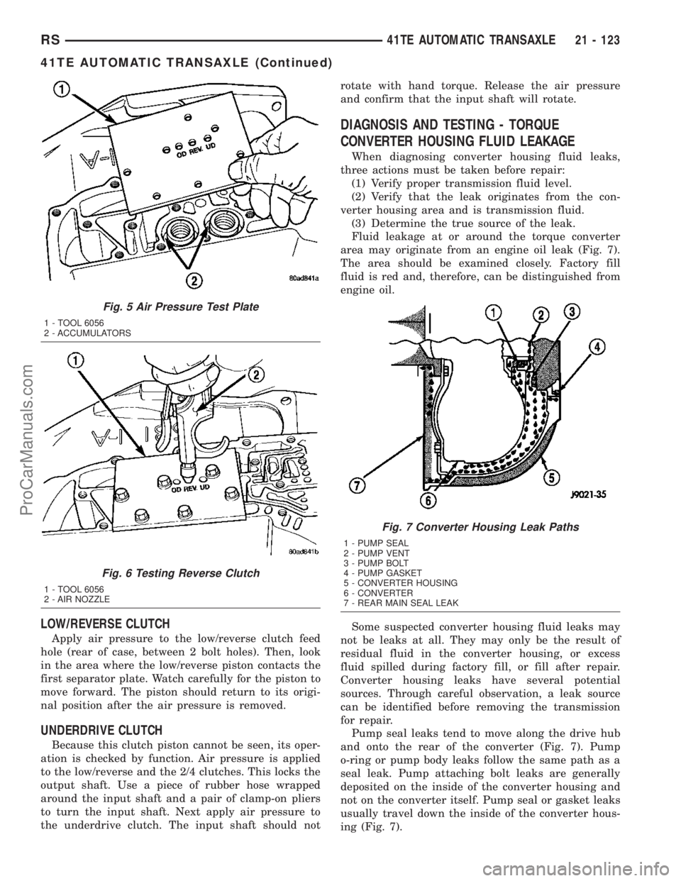
Fluid leakage at or around the torque converter
area may originate from an engine oil leak (Fig. 7).
The area should be examined closely. Factory fill
fluid is red and, therefore, can be distinguished from
engine oil.
Some suspected converter housing fluid leaks may
not be leaks at all. They may only be the result of
residual fluid in the converter housing, or excess
fluid spilled during factory fill, or fill after repair.
Converter housing leaks have several potential
sources. Through careful observation, a leak source
can be identified before removing the transmission
for repair.
Pump seal leaks tend to move along the drive hub
and onto the rear of the converter (Fig. 7). Pump
o-ring or pump body leaks follow the same path as a
seal leak. Pump attaching bolt leaks are generally
deposited on the inside of the converter housing and
not on the converter itself. Pump seal or gasket leaks
usually travel down the inside of the converter hous-
ing (Fig. 7).
Fig. 5 Air Pressure Test Plate
1 - TOOL 6056
2 - ACCUMULATORS
Fig. 6 Testing Reverse Clutch
1 - TOOL 6056
2 - AIR NOZZLE
Fig. 7 Converter Housing Leak Paths
1 - PUMP SEAL
2 - PUMP VENT
3 - PUMP BOLT
4 - PUMP GASKET
5 - CONVERTER HOUSING
6 - CONVERTER
7 - REAR MAIN SEAL LEAK
RS41TE AUTOMATIC TRANSAXLE21 - 123
41TE AUTOMATIC TRANSAXLE (Continued)
ProCarManuals.com
Page 1572 of 2177
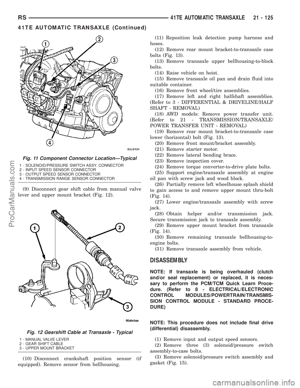
(9) Disconnect gear shift cable from manual valve
lever and upper mount bracket (Fig. 12).
(10) Disconnect crankshaft position sensor (if
equipped). Remove sensor from bellhousing.(11) Reposition leak detection pump harness and
hoses.
(12) Remove rear mount bracket-to-transaxle case
bolts (Fig. 13).
(13) Remove transaxle upper bellhousing-to-block
bolts.
(14) Raise vehicle on hoist.
(15) Remove transaxle oil pan and drain fluid into
suitable container.
(16) Remove front wheel/tire assemblies.
(17) Remove left and right halfshaft assemblies.
(Refer to 3 - DIFFERENTIAL & DRIVELINE/HALF
SHAFT - REMOVAL)
(18) AWD models: Remove power transfer unit.
(Refer to 21 - TRANSMISSION/TRANSAXLE/
POWER TRANSFER UNIT - REMOVAL)
(19) Remove rear mount bracket-to-transaxle case
lower (horizontal) bolt (Fig. 13).
(20) Remove front mount/bracket assembly.
(21) Remove starter motor.
(22) Remove lateral bending brace.
(23) Remove inspection cover.
(24) Remove torque converter-to-drive plate bolts.
(25) Support engine/transaxle assembly at engine
oil pan with screw jack and wood block.
(26) Partially remove left wheelhouse splash shield
to gain access to and remove upper mount thru-bolt
(Fig. 14).
(27) Lower engine/transaxle assembly with screw
jack.
(28) Obtain helper and/or transmission jack.
Secure transmission jack to transaxle assembly.
(29) Remove upper mount bracket from transaxle
(Fig. 14).
(30) Remove remaining transaxle bellhousing-to-
engine bolts.
(31) Remove transaxle assembly from vehicle.
DISASSEMBLY
NOTE: If transaxle is being overhauled (clutch
and/or seal replacement) or replaced, it is neces-
sary to perform the PCM/TCM Quick Learn Proce-
dure. (Refer to 8 - ELECTRICAL/ELECTRONIC
CONTROL MODULES/POWERTRAIN/TRANSMIS-
SION CONTROL MODULE - STANDARD PROCE-
DURE)
NOTE: This procedure does not include final drive
(differential) disassembly.
(1) Remove input and output speed sensors.
(2) Remove three (3) solenoid/pressure switch
assembly-to-case bolts.
(3) Remove solenoid/pressure switch assembly and
gasket (Fig. 15).
Fig. 11 Component Connector LocationÐTypical
1 - SOLENOID/PRESSURE SWITCH ASSY. CONNECTOR
2 - INPUT SPEED SENSOR CONNECTOR
3 - OUTPUT SPEED SENSOR CONNECTOR
4 - TRANSMISSION RANGE SENSOR CONNECTOR
Fig. 12 Gearshift Cable at Transaxle - Typical
1 - MANUAL VALVE LEVER
2 - GEAR SHIFT CABLE
3 - UPPER MOUNT BRACKET
RS41TE AUTOMATIC TRANSAXLE21 - 125
41TE AUTOMATIC TRANSAXLE (Continued)
ProCarManuals.com