2003 CHRYSLER CARAVAN seat memory
[x] Cancel search: seat memoryPage 1085 of 2177
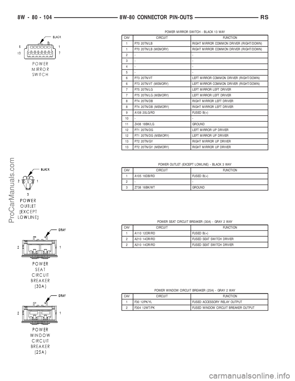
POWER MIRROR SWITCH - BLACK 13 WAY
CAV CIRCUIT FUNCTION
1 P70 20TN/LB RIGHT MIRROR COMMON DRIVER (RIGHT/DOWN)
1 P70 20TN/LB (MEMORY) RIGHT MIRROR COMMON DRIVER (RIGHT/DOWN)
2- -
3- -
4- -
5- -
6 P73 20TN/VT LEFT MIRROR COMMON DRIVER (RIGHT/DOWN)
6 P73 20TN/VT (MEMORY) LEFT MIRROR COMMON DRIVER (RIGHT/DOWN)
7 P75 20TN/LG LEFT MIRROR LEFT DRIVER
7 P75 20TN/LG (MEMORY) LEFT MIRROR LEFT DRIVER
8 P74 20TN/DB RIGHT MIRROR LEFT DRIVER
8 P74 20TN/DB (MEMORY) RIGHT MIRROR LEFT DRIVER
9 A108 20LG/RD FUSED B(+)
10 - -
11 Z408 18BK/LG GROUND
12 P71 20TN/DG LEFT MIRROR UP DRIVER
12 P71 20TN/DG (MEMORY) LEFT MIRROR UP DRIVER
13 P72 20TN/GY RIGHT MIRROR UP DRIVER
13 P72 20TN/GY (MEMORY) RIGHT MIRROR UP DRIVER
POWER OUTLET (EXCEPT LOWLINE) - BLACK 3 WAY
CAV CIRCUIT FUNCTION
1 A105 16DB/RD FUSED B(+)
2- -
3 Z738 16BK/WT GROUND
POWER SEAT CIRCUIT BREAKER (30A) - GRAY 2 WAY
CAV CIRCUIT FUNCTION
1 A110 12OR/RD FUSED B(+)
2 A210 14OR/RD FUSED SEAT SWITCH DRIVER
2 A210 14OR/RD FUSED SEAT SWITCH DRIVER
POWER WINDOW CIRCUIT BREAKER (25A) - GRAY 2 WAY
CAV CIRCUIT FUNCTION
1 F30 12PK/YL FUSED ACCESSORY RELAY OUTPUT
2 F304 12WT/PK FUSED WINDOW CIRCUIT BREAKER OUTPUT
8W - 80 - 104 8W-80 CONNECTOR PIN-OUTSRS
ProCarManuals.com
Page 1122 of 2177
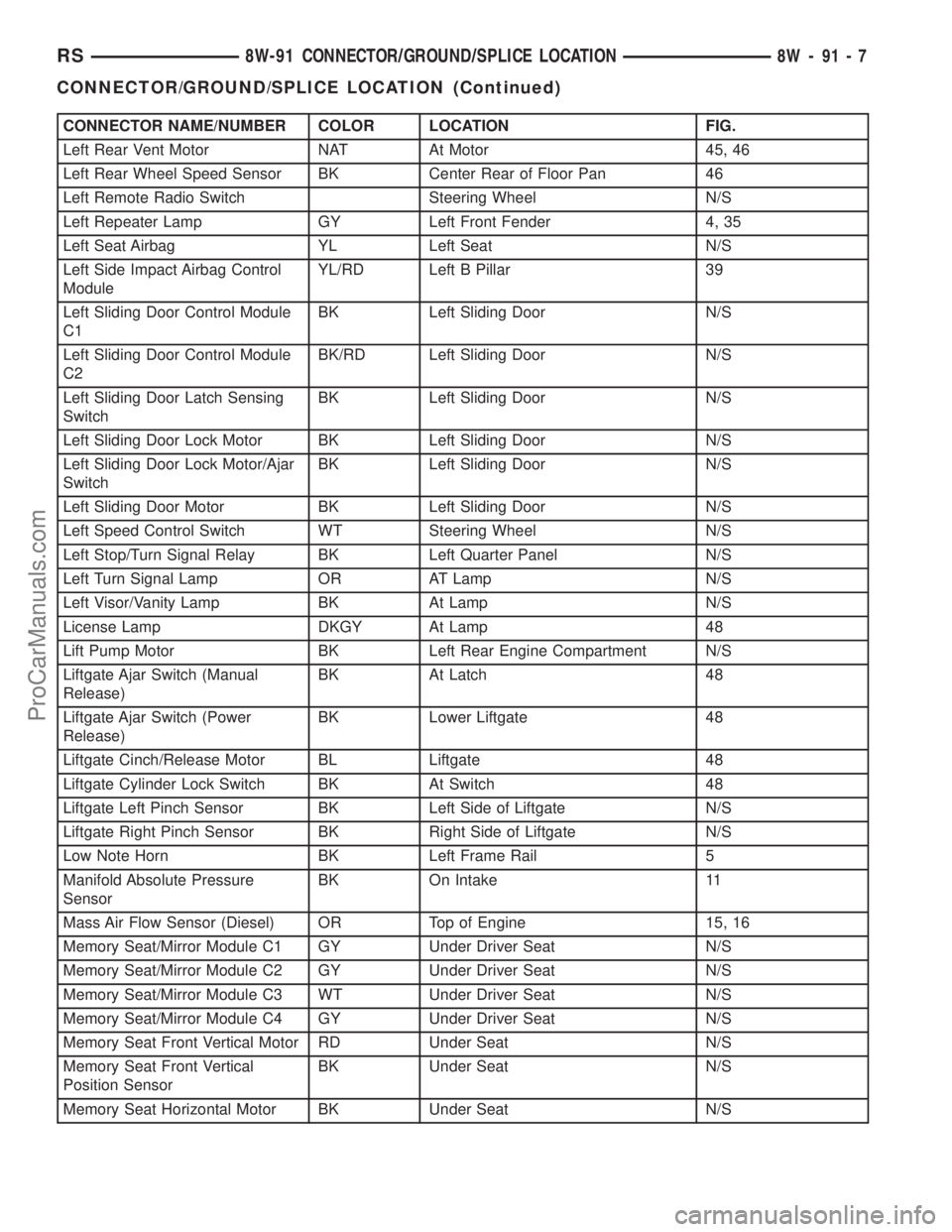
CONNECTOR NAME/NUMBER COLOR LOCATION FIG.
Left Rear Vent Motor NAT At Motor 45, 46
Left Rear Wheel Speed Sensor BK Center Rear of Floor Pan 46
Left Remote Radio Switch Steering Wheel N/S
Left Repeater Lamp GY Left Front Fender 4, 35
Left Seat Airbag YL Left Seat N/S
Left Side Impact Airbag Control
ModuleYL/RD Left B Pillar 39
Left Sliding Door Control Module
C1BK Left Sliding Door N/S
Left Sliding Door Control Module
C2BK/RD Left Sliding Door N/S
Left Sliding Door Latch Sensing
SwitchBK Left Sliding Door N/S
Left Sliding Door Lock Motor BK Left Sliding Door N/S
Left Sliding Door Lock Motor/Ajar
SwitchBK Left Sliding Door N/S
Left Sliding Door Motor BK Left Sliding Door N/S
Left Speed Control Switch WT Steering Wheel N/S
Left Stop/Turn Signal Relay BK Left Quarter Panel N/S
Left Turn Signal Lamp OR AT Lamp N/S
Left Visor/Vanity Lamp BK At Lamp N/S
License Lamp DKGY At Lamp 48
Lift Pump Motor BK Left Rear Engine Compartment N/S
Liftgate Ajar Switch (Manual
Release)BK At Latch 48
Liftgate Ajar Switch (Power
Release)BK Lower Liftgate 48
Liftgate Cinch/Release Motor BL Liftgate 48
Liftgate Cylinder Lock Switch BK At Switch 48
Liftgate Left Pinch Sensor BK Left Side of Liftgate N/S
Liftgate Right Pinch Sensor BK Right Side of Liftgate N/S
Low Note Horn BK Left Frame Rail 5
Manifold Absolute Pressure
SensorBK On Intake 11
Mass Air Flow Sensor (Diesel) OR Top of Engine 15, 16
Memory Seat/Mirror Module C1 GY Under Driver Seat N/S
Memory Seat/Mirror Module C2 GY Under Driver Seat N/S
Memory Seat/Mirror Module C3 WT Under Driver Seat N/S
Memory Seat/Mirror Module C4 GY Under Driver Seat N/S
Memory Seat Front Vertical Motor RD Under Seat N/S
Memory Seat Front Vertical
Position SensorBK Under Seat N/S
Memory Seat Horizontal Motor BK Under Seat N/S
RS8W-91 CONNECTOR/GROUND/SPLICE LOCATION8W-91-7
CONNECTOR/GROUND/SPLICE LOCATION (Continued)
ProCarManuals.com
Page 1123 of 2177
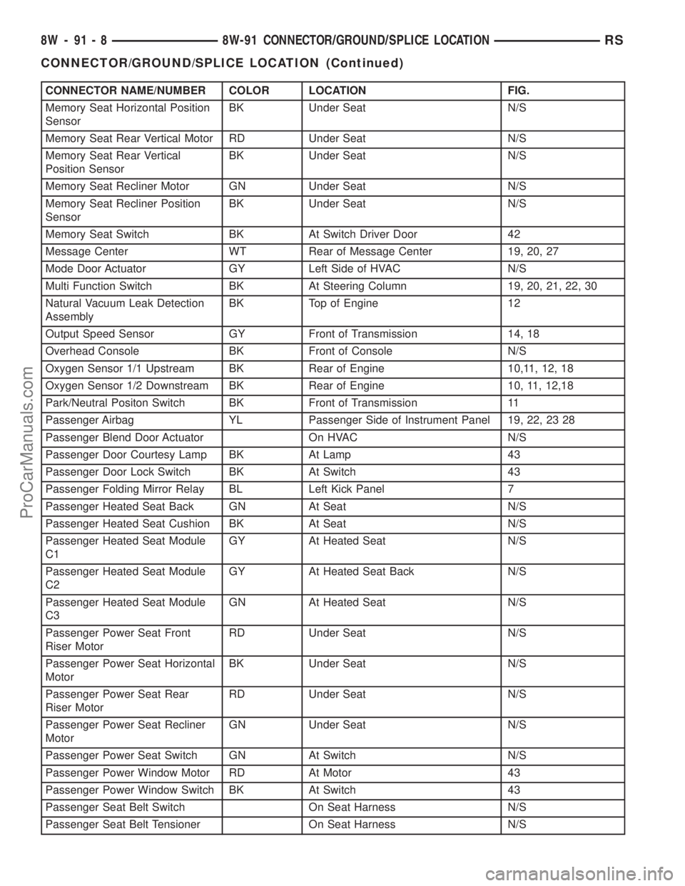
CONNECTOR NAME/NUMBER COLOR LOCATION FIG.
Memory Seat Horizontal Position
SensorBK Under Seat N/S
Memory Seat Rear Vertical Motor RD Under Seat N/S
Memory Seat Rear Vertical
Position SensorBK Under Seat N/S
Memory Seat Recliner Motor GN Under Seat N/S
Memory Seat Recliner Position
SensorBK Under Seat N/S
Memory Seat Switch BK At Switch Driver Door 42
Message Center WT Rear of Message Center 19, 20, 27
Mode Door Actuator GY Left Side of HVAC N/S
Multi Function Switch BK At Steering Column 19, 20, 21, 22, 30
Natural Vacuum Leak Detection
AssemblyBK Top of Engine 12
Output Speed Sensor GY Front of Transmission 14, 18
Overhead Console BK Front of Console N/S
Oxygen Sensor 1/1 Upstream BK Rear of Engine 10,11, 12, 18
Oxygen Sensor 1/2 Downstream BK Rear of Engine 10, 11, 12,18
Park/Neutral Positon Switch BK Front of Transmission 11
Passenger Airbag YL Passenger Side of Instrument Panel 19, 22, 23 28
Passenger Blend Door Actuator On HVAC N/S
Passenger Door Courtesy Lamp BK At Lamp 43
Passenger Door Lock Switch BK At Switch 43
Passenger Folding Mirror Relay BL Left Kick Panel 7
Passenger Heated Seat Back GN At Seat N/S
Passenger Heated Seat Cushion BK At Seat N/S
Passenger Heated Seat Module
C1GY At Heated Seat N/S
Passenger Heated Seat Module
C2GY At Heated Seat Back N/S
Passenger Heated Seat Module
C3GN At Heated Seat N/S
Passenger Power Seat Front
Riser MotorRD Under Seat N/S
Passenger Power Seat Horizontal
MotorBK Under Seat N/S
Passenger Power Seat Rear
Riser MotorRD Under Seat N/S
Passenger Power Seat Recliner
MotorGN Under Seat N/S
Passenger Power Seat Switch GN At Switch N/S
Passenger Power Window Motor RD At Motor 43
Passenger Power Window Switch BK At Switch 43
Passenger Seat Belt Switch On Seat Harness N/S
Passenger Seat Belt Tensioner On Seat Harness N/S
8W - 91 - 8 8W-91 CONNECTOR/GROUND/SPLICE LOCATIONRS
CONNECTOR/GROUND/SPLICE LOCATION (Continued)
ProCarManuals.com
Page 1129 of 2177
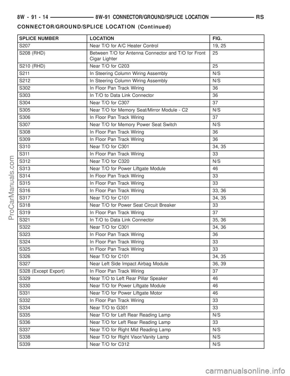
SPLICE NUMBER LOCATION FIG.
S207 Near T/O for A/C Heater Control 19, 25
S208 (RHD) Between T/O for Antenna Connector and T/O for Front
Cigar Lighter25
S210 (RHD) Near T/O for C203 25
S211 In Steering Column Wiring Assembly N/S
S212 In Steering Column Wiring Assembly N/S
S302 In Floor Pan Track Wiring 36
S303 In T/O to Data Link Connector 36
S304 Near T/O for C307 37
S305 Near T/O for Memory Seat/Mirror Module - C2 N/S
S306 In Floor Pan Track Wiring 37
S307 Near T/O for Memory Power Seat Switch N/S
S308 In Floor Pan Track Wiring 36
S309 In Floor Pan Track Wiring 36
S310 Near T/O for C301 34, 35
S311 In Floor Pan Track Wiring 33
S312 Near T/O for C320 N/S
S313 Near T/O for Power Liftgate Module 46
S314 In Floor Pan Track Wiring 33
S315 In Floor Pan Track Wiring 33
S316 In Floor Pan Track Wiring 33, 36
S317 Near T/O for C101 34, 35
S318 Near T/O for Power Seat Circuit Breaker 33
S319 In Floor Pan Track Wiring 37
S321 In T/O to Data Link Connector 35, 36
S322 Near T/O for C301 34, 36
S323 In Floor Pan Track Wiring 36
S324 In Floor Pan Track Wiring 33
S325 In Floor Pan Track Wiring 33
S326 Near T/O for C101 34, 35
S327 Near Left Side Impact Airbag Module 36, 39
S328 (Except Export) In Floor Pan Track Wiring 37
S329 Near T/O to Left Rear Pillar Speaker 46
S330 Near T/O for Power Liftgate Module 46
S331 Near T/O for Power Liftgate Motor 46
S332 In Floor Pan Track Wiring 33
S334 Near T/O to G301 33
S335 Near T/O for Left Rear Reading Lamp N/S
S336 Near T/O for Left Rear Reading Lamp 33
S337 Near T/O for Right Mid Reading Lamp N/S
S338 Near T/O for Right Visor/Vanity Lamp N/S
S339 Near T/O for C312 N/S
8W - 91 - 14 8W-91 CONNECTOR/GROUND/SPLICE LOCATIONRS
CONNECTOR/GROUND/SPLICE LOCATION (Continued)
ProCarManuals.com
Page 1178 of 2177
The IPM has a molded plastic cover that can be
removed to provide service access to all of the fuses
and relays in the IPM. An integral latch and hinges
are molded into the IPM cover for easy removal. A
fuse layout map is integral to the underside of the
IPM cover to ensure proper fuse and relay identifica-
tion. The IOD fuse is a 20 ampere blade-type mini
fuse and, when removed, it is stored in a fuse cavity
adjacent to the washer fuse within the IPM.
OPERATION
The term ignition-off draw identifies a normal con-
dition where power is being drained from the battery
with the ignition switch in the Off position. The IOD
fuse feeds the memory and sleep mode functions for
some of the electronic modules in the vehicle as well
as various other accessories that require battery cur-
rent when the ignition switch is in the Off position,
including the clock. The only reason the IOD fuse is
removed is to reduce the normal IOD of the vehicle
electrical system during new vehicle transportation
and pre-delivery storage to reduce battery depletion,
while still allowing vehicle operation so that the
vehicle can be loaded, unloaded and moved as needed
by both vehicle transportation company and dealer
personnel.
The IOD fuse is removed from the IPM fuse cavity
when the vehicle is shipped from the assembly plant.
Dealer personnel must install the IOD fuse when the
vehicle is being prepared for delivery in order to
restore full electrical system operation. Once the
vehicle is prepared for delivery, the IOD function of
this fuse becomes transparent and the fuse that has
been assigned the IOD designation becomes only
another Fused B(+) circuit fuse. The IOD fuse serves
no useful purpose to the dealer technician in the ser-
vice or diagnosis of any vehicle system or condition,
other than the same purpose as that of any other
standard circuit protection device.
The IOD fuse can be used by the vehicle owner as
a convenient means of reducing battery depletion
when a vehicle is to be stored for periods not to
exceed about thirty days. However, it must be
remembered that removing the IOD fuse will not
eliminate IOD, but only reduce this normal condition.
If a vehicle will be stored for more than about thirty
days, the battery negative cable should be discon-
nected to eliminate normal IOD; and, the battery
should be tested and recharged at regular intervals
during the vehicle storage period to prevent the bat-
tery from becoming discharged or damaged. Refer to
Battery Systemfor additional service information.
REMOVAL
(1) Turn the ignition switch to the Off position.(2) Unlatch and open the cover of the intelligent
power module.
(3) Remove the IOD fuse from fuse location
markedIODof the Integrated Power Module (IPM).
(4) Store the removed IOD fuse by installing it in
the unused fuse storage markedSPAREof the IPM.
(5) Close and latch the IPM.
INSTALLATION
(1) Be certain the ignition switch is in the Off posi-
tion.
(2) Unlatch and open the cover of the Integrated
Power Module (IPM).
(3) Use a thumb to press the IOD fuse firmly down
into IPM fuse cavity markedIOD.
(4) Close and latch the IPM cover.
POWER OUTLET
DESCRIPTION
Accessory power outlets are standard equipment on
this model. Two power outlets are installed in the
instrument panel center lower bezel, which is located
near the bottom of the instrument panel center stack
area. Two additional power outlets are also incorpo-
rated into the vehicle, one on the left rear C-pillar
trim and the other in the center console, if equipped.
The power outlets bases are secured by a snap fit in
the appropriate bezels. A hinged plug flips closed to
conceal and protect the power outlet base when the
power outlet is not being used.
The power outlet receptacle unit and the power
outlet plugs are each available for service replace-
ment.
OPERATION
The power outlet base or receptacle shell is con-
nected to ground, and an insulated contact in the
bottom of the shell is connected to battery current.
The power outlet on the instrument panel marked
with a battery receives battery voltage from a fuse in
the Integrated Power Module (IPM) at all times. The
other power outlet on the instrument panel marked
with a key receives battery voltage only when the
key is in the on position.
The power outlet located in the center console
receives battery voltage all the time when positioned
between thefront seatsand key-on voltage when
positioned between therear seats. The power outlet
located on the C-pillar receives battery voltage only
when the key is in the on position.
RS8W-97 POWER DISTRIBUTION SYSTEM8W-97-5
IOD FUSE (Continued)
ProCarManuals.com
Page 1754 of 2177
(6) Install clips to attach door trim to door frame
around perimeter of panel.
(7) If equipped, install screw to attach door trim to
door panel behind inside latch release handle.
(8) If equipped, connect power switch into wire
connector.
(9) Place power accessary switch in position on
door trim.
(10) Connect wire connector into memory seat/mir-
ror switch and install switch into trim panel.
(11) Install screws to attach accessary switch
panel to door trim.
(12) Install screw cover into switch panel.
(13) If equipped, install window crank.
(14) If equipped, install screws to attach trim
panel to door inside map pocket.
(15) If equipped, install screw to attach door pull
cup to inner door panel.
(16) If equipped, install screws to attach door
assist handle to inner door panel.
(17) Connect wire connector into courtesy lamp.
(18) Install lamp in door trim.
(19) Install switch bezel.
WATERSHIELD
REMOVAL
(1) Remove door trim panel. (Refer to 23 - BODY/
DOOR - FRONT/TRIM PANEL - REMOVAL)
(2) Remove the front door speaker. (Refer to 8 -
ELECTRICAL/AUDIO/SPEAKER - REMOVAL)
(3) Peel watershield away from adhesive around
perimeter of inner door panel.
INSTALLATION
(1) Insure that enough adhesive remains to
securely retain the water dam. Replace as necessary.
(2) Place the shield into position and press
securely to adhesive making sure to properly route
wiring and linkages.
(3) Install the front door speaker. (Refer to 8 -
ELECTRICAL/AUDIO/SPEAKER - INSTALLATION)
(4) Install door trim panel. (Refer to 23 - BODY/
DOOR - FRONT/TRIM PANEL - INSTALLATION)
WINDOW CRANK
REMOVAL
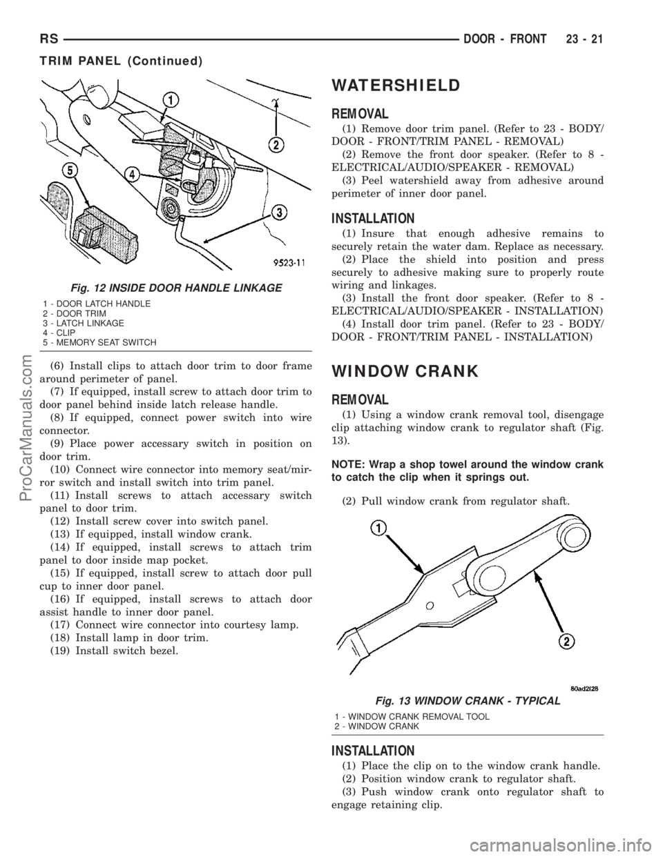
(1) Using a window crank removal tool, disengage
clip attaching window crank to regulator shaft (Fig.
13).
NOTE: Wrap a shop towel around the window crank
to catch the clip when it springs out.
(2) Pull window crank from regulator shaft.
INSTALLATION
(1) Place the clip on to the window crank handle.
(2) Position window crank to regulator shaft.
(3) Push window crank onto regulator shaft to
engage retaining clip.
Fig. 12 INSIDE DOOR HANDLE LINKAGE
1 - DOOR LATCH HANDLE
2 - DOOR TRIM
3 - LATCH LINKAGE
4 - CLIP
5 - MEMORY SEAT SWITCH
Fig. 13 WINDOW CRANK - TYPICAL
1 - WINDOW CRANK REMOVAL TOOL
2 - WINDOW CRANK
RSDOOR - FRONT23-21
TRIM PANEL (Continued)
ProCarManuals.com
Page 2119 of 2177
chemical reaction takes place. This means the con-
centration of oxygen will be the same downstream as
upstream. The output voltage of the downstream
O2S copies the voltage of the upstream sensor. The
only difference is a time lag (seen by the PCM)
between the switching of the O2S's.
To monitor the system, the number of lean-to-rich
switches of upstream and downstream O2S's is
counted. The ratio of downstream switches to
upstream switches is used to determine whether the
catalyst is operating properly. An effective catalyst
will have fewer downstream switches than it has
upstream switches i.e., a ratio closer to zero. For a
totally ineffective catalyst, this ratio will be one-to-
one, indicating that no oxidation occurs in the device.
The system must be monitored so that when cata-
lyst efficiency deteriorates and exhaust emissions
increase to over the legal limit, the MIL (Check
Engine lamp) will be illuminated.
NATURAL VACUUM LEAK DETECTION (NVLD) (if equipped)
The Natural Vacuum Leak Detection (NVLD) sys-
tem is the next generation evaporative leak detection
system that will first be used on vehicles equipped
with the Next Generation Controller (NGC). This
new system replaces the leak detection pump as the
method of evaporative system leak detection. This is
to detect a leak equivalent to a 0.0209(0.5 mm) hole.
This system has the capability to detect holes of this
size very dependably.
The basic leak detection theory employed with
NVLD is the9Gas Law9. This is to say that the pres-
sure in a sealed vessel will change if the temperature
of the gas in the vessel changes. The vessel will only
see this effect if it is indeed sealed. Even small leaks
will allow the pressure in the vessel to come to equi-
librium with the ambient pressure. In addition to the
detection of very small leaks, this system has the
capability of detecting medium as well as large evap-
orative system leaks.
The NVLD seals the canister vent during engine off
conditions. If the EVAP system has a leak of less than
the failure threshold, the evaporative system will be
pulled into a vacuum, either due to the cool down
from operating temperature or diurnal ambient tem-
perature cycling. The diurnal effect is considered one
of the primary contributors to the leak determination
by this diagnostic. When the vacuum in the system
exceeds about 19H2O (0.25 KPA), a vacuum switch
closes. The switch closure sends a signal to the NGC.
The NGC, via appropriate logic strategies (described
below), utilizes the switch signal, or lack thereof, to
make a determination of whether a leak is present.
The NVLD device is designed with a normally open
vacuum switch, a normally closed solenoid, and a
seal, which is actuated by both the solenoid and a
diaphragm. The NVLD is located on the atmosphericvent side of the canister. The NVLD assembly may
be mounted on top of the canister outlet, or in-line
between the canister and atmospheric vent filter. The
normally open vacuum switch will close with about 19
H2O (0.25 KPA) vacuum in the evaporative system.
The diaphragm actuates the switch. This is above the
opening point of the fuel inlet check valve in the fill
tube so cap off leaks can be detected. Submerged fill
systems must have recirculation lines that do not
have the in-line normally closed check valve that pro-
tects the system from failed nozzle liquid ingestion,
in order to detect cap off conditions.
The normally closed valve in the NVLD is intended
to maintain the seal on the evaporative system dur-
ing the engine off condition. If vacuum in the evapo-
rative system exceeds 39to 69H2O (0.75 to 1.5 KPA),
the valve will be pulled off the seat, opening the seal.
This will protect the system from excessive vacuum
as well as allowing sufficient purge flow in the event
that the solenoid was to become inoperative.
The solenoid actuates the valve to unseal the can-
ister vent while the engine is running. It also will be
used to close the vent during the medium and large
leak tests and during the purge flow check. This sole-
noid requires initial 1.5 amps of current to pull the
valve open but after 100 ms. will be duty cycled down
to an average of about 150 mA for the remainder of
the drive cycle.
Another feature in the device is a diaphragm that
will open the seal in the NVLD with pressure in the
evaporative system. The device will9blow off9at
about 0.59H2O (0.12 KPA) pressure to permit the
venting of vapors during refueling. An added benefit
to this is that it will also allow the tank to9breathe9
during increasing temperatures, thus limiting the
pressure in the tank to this low level. This is benefi-
cial because the induced vacuum during a subse-
quent declining temperature will achieve the switch
closed (pass threshold) sooner than if the tank had to
decay from a built up pressure.
The device itself has 3 wires: Switch sense, sole-
noid driver and ground. It also includes a resistor to
protect the switch from a short to battery or a short
to ground. The NGC utilizes a high-side driver to
energize and duty-cycle the solenoid.
DESCRIPTION - HIGH AND LOW LIMITS
The PCM compares input signal voltages from each
input device with established high and low limits for
the device. If the input voltage is not within limits
and other criteria are met, the PCM stores a diagnos-
tic trouble code in memory. Other diagnostic trouble
code criteria might include engine RPM limits or
input voltages from other sensors or switches that
must be present before verifying a diagnostic trouble
code condition.
25 - 8 EMISSIONS CONTROLRS
EMISSIONS CONTROL (Continued)
ProCarManuals.com
Page 2159 of 2177
MANUAL ADJUSTER - INSTALLATION,
FRONT SEAT TRACK..................23-94
MANUAL ADJUSTER - REMOVAL, FRONT
SEAT TRACK........................23-94
MANUAL THREE ZONE - DESCRIPTION....24-1
MANUAL THREE ZONE - OPERATION......24-3
MANUAL TRACK - INSTALLATION,
FRONT SEAT RISER...................23-93
MANUAL TRACK - REMOVAL, FRONT
SEAT RISER.........................23-93
MANUAL TRANSAXLE - ASSEMBLY, T850 . 21-42
MANUAL TRANSAXLE - DESCRIPTION,
T850..............................21-21
MANUAL TRANSAXLE - DISASSEMBLY,
T850..............................21-35
MANUAL TRANSAXLE - INSTALLATION,
T850..............................21-51
MANUAL TRANSAXLE - OPERATION,
T850..............................21-24
MANUAL TRANSAXLE - REMOVAL, T850 . . 21-31
MANUAL TRANSAXLE - SPECIFICATIONS,
T850..............................21-56
MANUFACTURER PLATE - DESCRIPTION . Intro.-11
MAP SENSOR - DESCRIPTION..........14-30
MAP SENSOR - OPERATION............14-30
MASTER CYLINDER - LHD -
INSTALLATION........................6-10
MASTER CYLINDER - LHD - REMOVAL.....6-9
MASTER CYLINDER - RHD -
INSTALLATION.........................6-9
MASTER CYLINDER - RHD - REMOVAL.......6-8
MASTER CYLINDER BLEEDING -
STANDARD PROCEDURE................5-35
MASTER CYLINDER (FLUID RESERVOIR)
- ASSEMBLY.........................5-38
MASTER CYLINDER (FLUID RESERVOIR)
- DISASSEMBLY......................5-37
MATCH MOUNTING - STANDARD
PROCEDURE, TIRE AND WHEEL..........22-7
MATS - INSTALLATION, CARPETS AND
FLOOR.............................23-75
MATS - REMOVAL, CARPETS AND
FLOOR.............................23-74
MEASUREMENT - STANDARD
PROCEDURE, CURB HEIGHT.............2-54
MEASUREMENTS - SPECIFICATIONS,
GAP AND FLUSH....................23-121
MEASURING BEARING CLEARANCE
USING PLASTIGAGE - STANDARD
PROCEDURE.....................9-12,9-84
MEASURING CAMSHAFT END PLAY -
STANDARD PROCEDURE................9-29
MEASURING CONNECTING ROD
BEARING CLEARANCE - STANDARD
PROCEDURE........................9-120
MEASURING CRANKSHAFT END PLAY -
STANDARD PROCEDURE...............9-125
MEASURING TIMING CHAIN WEAR -
STANDARD PROCEDURE...............9-153
MECHANICAL - DIAGNOSIS AND
TESTING, ENGINE DIAGNOSIS........9-6,9-80
MECHANISM - INSTALLATION,
GEARSHIFT.........................21-89
MECHANISM - REMOVAL, GEARSHIFT....21-87
MEMORIES, OPERATION - FUEL
CORRECTION OR ADAPTIVE............14-20
MEMORY SEAT/MIRROR MODULE -
DESCRIPTION.......................8E-10
MEMORY SEAT/MIRROR MODULE -
DIAGNOSIS AND TESTING
.............8E-10
MEMORY SEAT/MIRROR MODULE -
INSTALLATION
.......................8E-10
MEMORY SEAT/MIRROR MODULE -
OPERATION
.........................8E-10
MEMORY SEAT/MIRROR MODULE -
REMOVAL
..........................8E-10
MEMORY SET SWITCH - DESCRIPTION
. . . 8N-55
MEMORY SET SWITCH - INSTALLATION
. . 8N-56
MEMORY SET SWITCH - OPERATION
....8N-56
MEMORY SET SWITCH - REMOVAL
......8N-56
MEMORY SWITCH - DIAGNOSIS AND
TESTING
...........................8N-56
MEMORY SYSTEM - DESCRIPTION
......8N-51
MEMORY SYSTEM - DIAGNOSIS AND
TESTING
...........................8N-53
MEMORY SYSTEM - OPERATION
........8N-52
METRIC SYSTEM - DESCRIPTION
......Intro.-6MINI-TRIP COMPUTER - DIAGNOSIS
AND TESTING, COMPASS.............8M-10
MIRROR - DESCRIPTION, AUTOMATIC
DAY / NIGHT........................8N-47
MIRROR - DIAGNOSIS AND TESTING,
AUTOMATIC DAY / NIGHT..............8N-47
MIRROR - INSTALLATION, REAR VIEW . . . 23-80
MIRROR - INSTALLATION, SIDE VIEW....23-57
MIRROR - OPERATION, AUTOMATIC DAY
/ NIGHT............................8N-47
MIRROR - REMOVAL, REAR VIEW.......23-79
MIRROR - REMOVAL, SIDE VIEW........23-57
MIRROR - REMOVAL, SIDEVIEW........8N-49
MIRROR - STANDARD PROCEDURE,
HEATED.............................8G-6
MIRROR GLASS - INSTALLATION, SIDE
VIEW..............................23-58
MIRROR GLASS - REMOVAL, SIDE VIEW . . 23-58
MIRROR SWITCH - DESCRIPTION........8G-5
MIRROR SWITCH - EXPORT -
DESCRIPTION, POWER FOLDAWAY......8N-48
MIRROR SWITCH - EXPORT -
INSTALLATION, POWER FOLDAWAY......8N-49
MIRROR SWITCH - EXPORT -
OPERATION, POWER FOLDAWAY........8N-48
MIRROR SWITCH - EXPORT - REMOVAL,
POWER FOLDAWAY..................8N-48
MIRROR SWITCH - OPERATION..........8G-5
MIRROR TEST - DIAGNOSIS AND
TESTING, HEATED.....................8G-5
MIRRORS - DESCRIPTION, HEATED........8G-5
MIRRORS - DESCRIPTION, POWER......8N-45
MIRRORS - DIAGNOSIS AND TESTING,
POWER............................8N-46
MIRRORS - OPERATION, HEATED........8G-5
MIRRORS - OPERATION, POWER........8N-45
MISALIGNMENT - DIAGNOSIS AND
TESTING, DRIVE PLATE.................6-6
MODE DOOR ACTUATOR - DESCRIPTION . . 24-24
MODE DOOR ACTUATOR -
INSTALLATION..................24-25,24-36
MODE DOOR ACTUATOR - OPERATION . . . 24-24
MODE DOOR ACTUATOR - REMOVAL....24-25,
24-36
MODE, OPERATION - DRB IIITS TAT E
DISPLAY TEST........................25-9
MODES OF OPERATION - OPERATION....14-18
MODULAR CLUTCH ASSY - 2.4L GAS -
INSTALLATION........................6-11
MODULAR CLUTCH ASSY - 2.4L GAS -
REMOVAL...........................6-11
MODULE - DESCRIPTION, BODY
CONTROL...........................8E-3
MODULE - DESCRIPTION, FRONT
CONTROL...........................8E-7
MODULE - DESCRIPTION, FUEL PUMP....14-8
MODULE - DESCRIPTION, HEATED SEAT . . . 8E-8
MODULE - DESCRIPTION, INTEGRATED
POWER..........................8W-97-3
MODULE - DESCRIPTION, MEMORY
SEAT/MIRROR.......................8E-10
MODULE - DESCRIPTION, POWER . . 24-25,24-37
MODULE - DESCRIPTION, POWER
LIFTGATE CONTROL..................8E-10
MODULE - DESCRIPTION, REAR
DRIVELINE...........................3-23
MODULE - DESCRIPTION, REMOTE
KEYLESS ENTRY.....................8N-43
MODULE - DESCRIPTION, SENTRY KEY
IMMOBILIZER.......................8E-18
MODULE - DESCRIPTION, SIDE IMPACT
AIRBAG CONTROL...................8O-17
MODULE - DESCRIPTION, SLIDING
DOOR CONTROL.....................8E-19
MODULE - DESCRIPTION,
TRANSMISSION CONTROL.............8E-20
MODULE - DIAGNOSIS AND TESTING,
FRONT CONTROL.....................8E-7
MODULE - DIAGNOSIS AND TESTING,
HEATED SEAT
........................8E-9
MODULE - DIAGNOSIS AND TESTING,
MEMORY SEAT/MIRROR
...............8E-10
MODULE - DIAGNOSIS AND TESTING,
REMOTE KEYLESS ENTRY
.............8N-43
MODULE - EXPORT - DESCRIPTION,
ANTENNA
...........................8A-6
MODULE - EXPORT - DIAGNOSIS AND
TESTING, ANTENNA
...................8A-7MODULE - EXPORT - INSTALLATION,
ANTENNA...........................8A-7
MODULE - EXPORT - OPERATION,
ANTENNA...........................8A-6
MODULE - EXPORT - REMOVAL,
ANTENNA...........................8A-7
MODULE - INSTALLATION, BODY
CONTROL...........................8E-5
MODULE - INSTALLATION, FRONT
CONTROL...........................8E-8
MODULE - INSTALLATION, FUEL PUMP....14-9
MODULE - INSTALLATION, HEATED SEAT . . 8E-10
MODULE - INSTALLATION, INTEGRATED
POWER..........................8W-97-4
MODULE - INSTALLATION, MEMORY
SEAT/MIRROR.......................8E-10
MODULE - INSTALLATION, POWER . 24-26,24-38
MODULE - INSTALLATION, POWER
LIFTGATE CONTROL..................8E-11
MODULE - INSTALLATION, REMOTE
KEYLESS ENTRY.....................8N-44
MODULE - INSTALLATION, SENTRY KEY
IMMOBILIZER.......................8E-19
MODULE - INSTALLATION, SIDE IMPACT
AIRBAG CONTROL...................8O-17
MODULE - INSTALLATION, SLIDING
DOOR CONTROL.....................8E-20
MODULE - INSTALLATION, WIPER.......8R-18
MODULE - OPERATION, BODY CONTROL . . . 8E-3
MODULE - OPERATION, FRONT
CONTROL...........................8E-7
MODULE - OPERATION, FUEL PUMP........14-8
MODULE - OPERATION, HEATED SEAT.....8E-9
MODULE - OPERATION, INTEGRATED
POWER..........................8W-97-3
MODULE - OPERATION, MEMORY
SEAT/MIRROR.......................8E-10
MODULE - OPERATION, POWER....24-26,24-37
MODULE - OPERATION, POWER
LIFTGATE CONTROL..................8E-11
MODULE - OPERATION, REAR
DRIVELINE...........................3-23
MODULE - OPERATION, REMOTE
KEYLESS ENTRY.....................8N-43
MODULE - OPERATION, SENTRY KEY
IMMOBILIZER.......................8E-18
MODULE - OPERATION, SIDE IMPACT
AIRBAG CONTROL...................8O-17
MODULE - OPERATION, SLIDING DOOR
CONTROL..........................8E-19
MODULE - OPERATION, TRANSMISSION
CONTROL..........................8E-20
MODULE - REMOVAL, BODY CONTROL....8E-4
MODULE - REMOVAL, FRONT CONTROL . . . 8E-8
MODULE - REMOVAL, FUEL PUMP........14-8
MODULE - REMOVAL, HEATED SEAT......8E-9
MODULE - REMOVAL, INTEGRATED
POWER..........................8W-97-4
MODULE - REMOVAL, MEMORY
SEAT/MIRROR.......................8E-10
MODULE - REMOVAL, POWER.....24-26,24-37
MODULE - REMOVAL, POWER LIFTGATE
CONTROL..........................8E-11
MODULE - REMOVAL, REMOTE KEYLESS
ENTRY
.............................8N-44
MODULE - REMOVAL, SENTRY KEY
IMMOBILIZER
.......................8E-18
MODULE - REMOVAL, SIDE IMPACT
AIRBAG CONTROL
...................8O-17
MODULE - REMOVAL, SLIDING DOOR
CONTROL
..........................8E-19
MODULE - REMOVAL, WIPER
...........8R-18
MODULE - SPECIFICATIONS, REAR
DRIVELINE
...........................3-34
MODULE, BENCH SEAT - REMOVAL,
CHILD SEAT
.........................23-86
MODULE LAMP REPLACEMENT -
STANDARD PROCEDURE
...............8M-3
MODULE NOISE - DIAGNOSIS AND
TESTING, REAR DRIVELINE
.............3-24
MODULE OPERATION - DIAGNOSIS AND
TESTING, REAR DRIVELINE
.............3-26
MOLDING - INSTALLATION, FRONT
DOOR INNER BELT
..................23-112
MOLDING - INSTALLATION, FRONT
DOOR OUTER BELT
..................23-110
MOLDING - INSTALLATION, ROOF JOINT
. . 23-57
20 INDEXRS
Description Group-Page Description Group-Page Description Group-Page
ProCarManuals.com