2003 CHRYSLER CARAVAN remove seats
[x] Cancel search: remove seatsPage 1808 of 2177

(15) Roll and fold carpet forward away from rear
door opening.
(16) Extract carpet through sliding door opening
(Fig. 5).
INSTALLATION
(1) Insert carpet through sliding door opening.
(2) Roll carpet rearward toward rear door opening.
(3) Roll carpet under instrument panel.(4) Install push pins fasteners through carpet and
grommet into floor to attach carpet to floor in front
seat area (Fig. 5).
(5) Install push pins fasteners in the rear area.
CAUTION: Ensure that the correct fasteners are
installed in the proper locations. Damage to the fuel
tank may result.
(6) Install floor escutcheons (Fig. 4).
(7) Install the floor console trays. (Refer to 23 -
BODY/INTERIOR/FLOOR CONSOLE TRAY -
INSTALLATION)
(8) Install Quarter trim panels.
(9) Install D-pillar trim covers.
(10) Install lower B-pillar trim covers.
(11) Install rear door sill plate.
(12) Install sliding door sill plates. (Refer to 23 -
BODY/INTERIOR/SLIDING DOOR SILL PLATE -
INSTALLATION)
(13) Install front cowl panels and sill plates.
(14) Install the passenger seats. Refer to the Own-
er's Manual for proper procedures.
(15) Install front center console.
(16) Install front seats. (Refer to 23 - BODY/
SEATS/SEAT - INSTALLATION)
COWL TRIM
REMOVAL
(1) Remove door sill plate.
(2) Disengage hidden clips holding cowl trim to
cowl panel (Fig. 1).
(3) Remove cowl trim from vehicle.
INSTALLATION
(1) Place cowl trim panel in position on vehicle
(Fig. 1).
(2) Engage hidden clips attaching cowl trim to
cowl panel.
(3) Install door sill plate.
C-PILLAR TRIM
REMOVAL
(1) Remove quarter trim panel.
(2) Remove seat belt turning loop from height
adjuster.
(3) Remove screw attaching C-pillar trim panel to
C-pillar (Fig. 6).
(4) Disengage hidden clips attaching trim to upper
C-pillar.
(5) Remove upper C-pillar trim from vehicle.
Fig. 4 SEAT ESCUTCHEONS
1 - SEAT ESCUTCHEON
2 - FLOOR CARPET
Fig. 5 FLOOR CARPET
1 - CARPET LOCATOR GROMMET
2 - PUSH PIN
3 - CARPET
4 - CARPET GROMMET
5 - HEEL PROTECTOR PAD
6 - BODY ASSEMBLY
RSINTERIOR23-75
CARPETS AND FLOOR MATS (Continued)
ProCarManuals.com
Page 1819 of 2177
BENCH SEAT TRACK
REMOVAL............................102
INSTALLATION........................102
PLASTIC GROCERY BAG RETAINER
REMOVAL............................103
INSTALLATION........................103
UNDER SEAT STORAGE BIN
REMOVAL............................103
INSTALLATION........................103UNDER SEAT STORAGE BIN GUIDE
REMOVAL............................104
INSTALLATION........................104
UNDER SEAT STORAGE BIN LOCK/LATCH
REMOVAL............................104
INSTALLATION........................104
LUMBAR SUPPORT
REMOVAL............................104
INSTALLATION........................104
CHILD SEAT MODULE, BENCH
SEAT
REMOVAL
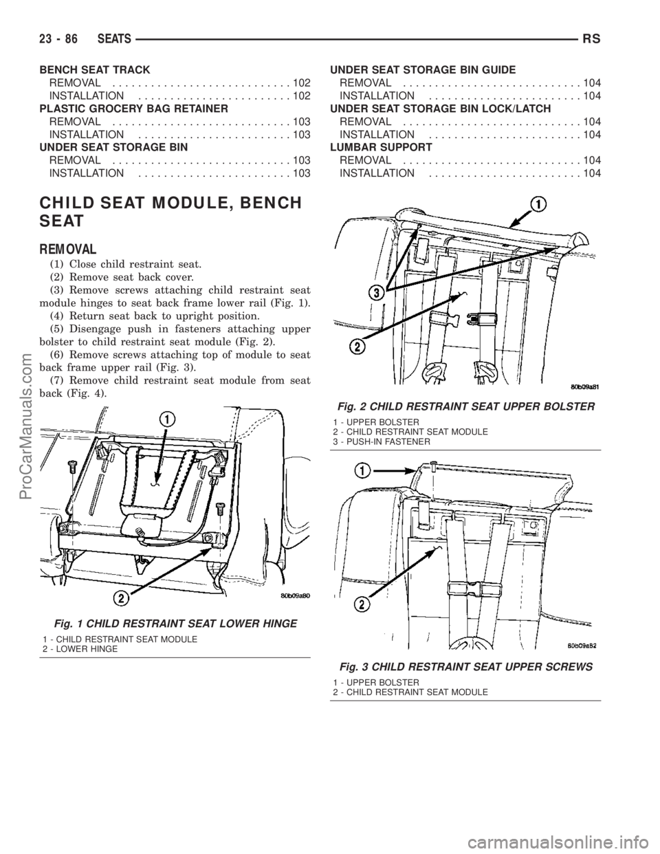
(1) Close child restraint seat.
(2) Remove seat back cover.
(3) Remove screws attaching child restraint seat
module hinges to seat back frame lower rail (Fig. 1).
(4) Return seat back to upright position.
(5) Disengage push in fasteners attaching upper
bolster to child restraint seat module (Fig. 2).
(6) Remove screws attaching top of module to seat
back frame upper rail (Fig. 3).
(7) Remove child restraint seat module from seat
back (Fig. 4).
Fig. 1 CHILD RESTRAINT SEAT LOWER HINGE
1 - CHILD RESTRAINT SEAT MODULE
2 - LOWER HINGE
Fig. 2 CHILD RESTRAINT SEAT UPPER BOLSTER
1 - UPPER BOLSTER
2 - CHILD RESTRAINT SEAT MODULE
3 - PUSH-IN FASTENER
Fig. 3 CHILD RESTRAINT SEAT UPPER SCREWS
1 - UPPER BOLSTER
2 - CHILD RESTRAINT SEAT MODULE
23 - 86 SEATSRS
ProCarManuals.com
Page 1820 of 2177
INSTALLATION
INSTALLATION
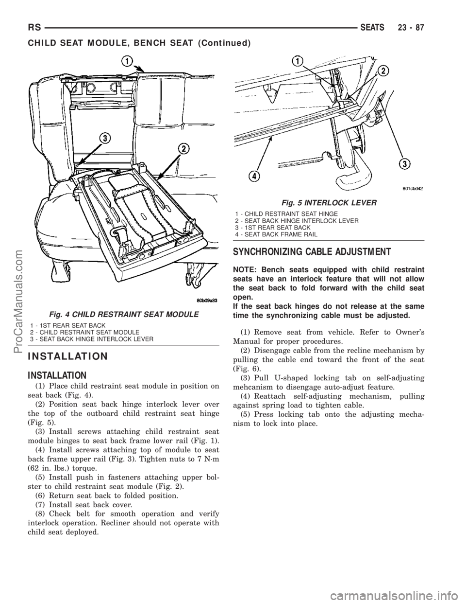
(1) Place child restraint seat module in position on
seat back (Fig. 4).
(2) Position seat back hinge interlock lever over
the top of the outboard child restraint seat hinge
(Fig. 5).
(3) Install screws attaching child restraint seat
module hinges to seat back frame lower rail (Fig. 1).
(4) Install screws attaching top of module to seat
back frame upper rail (Fig. 3). Tighten nuts to 7 N´m
(62 in. lbs.) torque.
(5) Install push in fasteners attaching upper bol-
ster to child restraint seat module (Fig. 2).
(6) Return seat back to folded position.
(7) Install seat back cover.
(8) Check belt for smooth operation and verify
interlock operation. Recliner should not operate with
child seat deployed.
SYNCHRONIZING CABLE ADJUSTMENT
NOTE: Bench seats equipped with child restraint
seats have an interlock feature that will not allow
the seat back to fold forward with the child seat
open.
If the seat back hinges do not release at the same
time the synchronizing cable must be adjusted.
(1) Remove seat from vehicle. Refer to Owner's
Manual for proper procedures.
(2) Disengage cable from the recline mechanism by
pulling the cable end toward the front of the seat
(Fig. 6).
(3) Pull U-shaped locking tab on self-adjusting
mehcanism to disengage auto-adjust feature.
(4) Reattach self-adjusting mechanism, pulling
against spring load to tighten cable.
(5) Press locking tab onto the adjusting mecha-
nism to lock into place.
Fig. 4 CHILD RESTRAINT SEAT MODULE
1 - 1ST REAR SEAT BACK
2 - CHILD RESTRAINT SEAT MODULE
3 - SEAT BACK HINGE INTERLOCK LEVER
Fig. 5 INTERLOCK LEVER
1 - CHILD RESTRAINT SEAT HINGE
2 - SEAT BACK HINGE INTERLOCK LEVER
3 - 1ST REAR SEAT BACK
4 - SEAT BACK FRAME RAIL
RSSEATS23-87
CHILD SEAT MODULE, BENCH SEAT (Continued)
ProCarManuals.com
Page 1821 of 2177
QUAD CHILD SEAT
REMOVAL
(1) Remove the seat. Refer to Owner's Manual for
proper procedures.
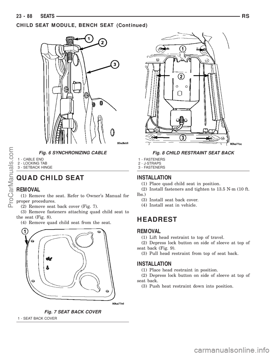
(2) Remove seat back cover (Fig. 7).
(3) Remove fasteners attaching quad child seat to
the seat (Fig. 8).
(4) Remove quad child seat from the seat.
INSTALLATION
(1) Place quad child seat in position.
(2) Install fasteners and tighten to 13.5 N´m (10 ft.
lbs.)
(3) Install seat back cover.
(4) Install seat in vehicle.
HEADREST
REMOVAL
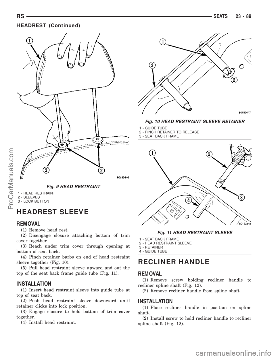
(1) Lift head restraint to top of travel.
(2) Depress lock button on side of sleeve at top of
seat back (Fig. 9).
(3) Pull head restraint from top of seat back.
INSTALLATION
(1) Place head restraint in position.
(2) Depress lock button on side of sleeve at top of
seat back.
(3) Push heat restraint down into position.
Fig. 6 SYNCHRONIZING CABLE
1 - CABLE END
2 - LOCKING TAB
3 - SETBACK HINGE
Fig. 7 SEAT BACK COVER
1 - SEAT BACK COVER
Fig. 8 CHILD RESTRAINT SEAT BACK
1 - FASTENERS
2 - J-STRAPS
3 - FASTENERS
23 - 88 SEATSRS
CHILD SEAT MODULE, BENCH SEAT (Continued)
ProCarManuals.com
Page 1822 of 2177
HEADREST SLEEVE
REMOVAL
(1) Remove head rest.
(2) Disengage closure attaching bottom of trim
cover together.
(3) Reach under trim cover through opening at
bottom of seat back.
(4) Pinch retainer barbs on end of head restraint
sleeve together (Fig. 10).
(5) Pull head restraint sleeve upward and out the
top of the seat back frame guide tube (Fig. 11).
INSTALLATION
(1) Insert head restraint sleeve into guide tube at
top of seat back.
(2) Push head restraint sleeve downward until
retainer clicks into lock position.
(3) Engage closure to hold bottom of trim cover
together.
(4) Install head restraint.
RECLINER HANDLE
REMOVAL
(1) Remove screw holding recliner handle to
recliner spline shaft (Fig. 12).
(2) Remove recliner handle from spline shaft.
INSTALLATION
(1) Place recliner handle in position on spline
shaft.
(2) Install screw to hold recliner handle to recliner
spline shaft (Fig. 12).
Fig. 9 HEAD RESTRAINT
1 - HEAD RESTRAINT
2 - SLEEVES
3 - LOCK BUTTON
Fig. 10 HEAD RESTRAINT SLEEVE RETAINER
1 - GUIDE TUBE
2 - PINCH RETAINER TO RELEASE
3 - SEAT BACK FRAME
Fig. 11 HEAD RESTRAINT SLEEVE
1 - SEAT BACK FRAME
2 - HEAD RESTRAINT SLEEVE
3 - RETAINER
4 - GUIDE TUBE
RSSEATS23-89
HEADREST (Continued)
ProCarManuals.com
Page 1823 of 2177
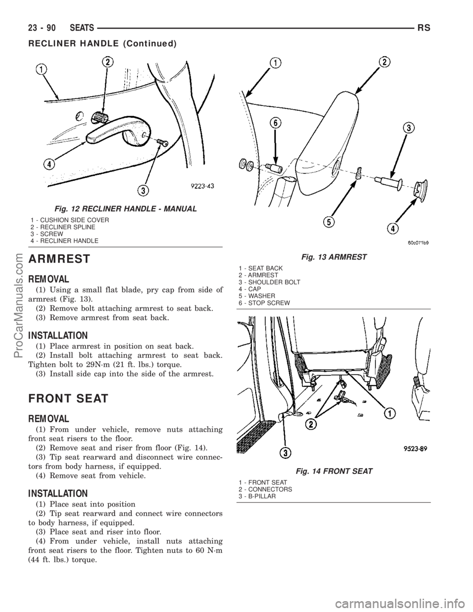
ARMREST
REMOVAL
(1) Using a small flat blade, pry cap from side of
armrest (Fig. 13).
(2) Remove bolt attaching armrest to seat back.
(3) Remove armrest from seat back.
INSTALLATION
(1) Place armrest in position on seat back.
(2) Install bolt attaching armrest to seat back.
Tighten bolt to 29N´m (21 ft. lbs.) torque.
(3) Install side cap into the side of the armrest.
FRONT SEAT
REMOVAL
(1) From under vehicle, remove nuts attaching
front seat risers to the floor.
(2) Remove seat and riser from floor (Fig. 14).
(3) Tip seat rearward and disconnect wire connec-
tors from body harness, if equipped.
(4) Remove seat from vehicle.
INSTALLATION
(1) Place seat into position
(2) Tip seat rearward and connect wire connectors
to body harness, if equipped.
(3) Place seat and riser into floor.
(4) From under vehicle, install nuts attaching
front seat risers to the floor. Tighten nuts to 60 N´m
(44 ft. lbs.) torque.
Fig. 12 RECLINER HANDLE - MANUAL
1 - CUSHION SIDE COVER
2 - RECLINER SPLINE
3 - SCREW
4 - RECLINER HANDLE
Fig. 13 ARMREST
1 - SEAT BACK
2 - ARMREST
3 - SHOULDER BOLT
4 - CAP
5 - WASHER
6 - STOP SCREW
Fig. 14 FRONT SEAT
1 - FRONT SEAT
2 - CONNECTORS
3 - B-PILLAR
23 - 90 SEATSRS
RECLINER HANDLE (Continued)
ProCarManuals.com
Page 1824 of 2177
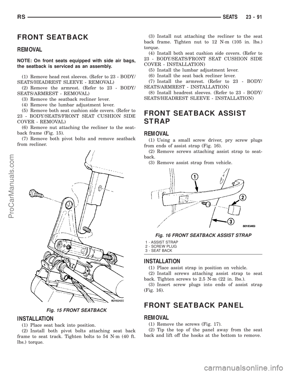
FRONT SEATBACK
REMOVAL
NOTE: On front seats equipped with side air bags,
the seatback is serviced as an assembly.
(1) Remove head rest sleeves. (Refer to 23 - BODY/
SEATS/HEADREST SLEEVE - REMOVAL)
(2) Remove the armrest. (Refer to 23 - BODY/
SEATS/ARMREST - REMOVAL)
(3) Remove the seatback recliner lever.
(4) Remove the lumbar adjustment lever.
(5) Remove both seat cushion side covers. (Refer to
23 - BODY/SEATS/FRONT SEAT CUSHION SIDE
COVER - REMOVAL)
(6) Remove nut attaching the recliner to the seat-
back frame (Fig. 15).
(7) Remove both pivot bolts and remove seatback
from recliner.
INSTALLATION
(1) Place seat back into position.
(2) Install both pivot bolts attaching seat back
frame to seat track. Tighten bolts to 54 N´m (40 ft.
lbs.) torque.(3) Install nut attaching the recliner to the seat
back frame. Tighten nut to 12 N´m (105 in. lbs.)
torque.
(4) Install both seat cushion side covers. (Refer to
23 - BODY/SEATS/FRONT SEAT CUSHION SIDE
COVER - INSTALLATION)
(5) Install the lumbar adjustment lever.
(6) Install the seat back recliner lever.
(7) Install the armrest. (Refer to 23 - BODY/
SEATS/ARMREST - INSTALLATION)
(8) Install headrest sleeves. (Refer to 23 - BODY/
SEATS/HEADREST SLEEVE - INSTALLATION)
FRONT SEATBACK ASSIST
STRAP
REMOVAL
(1) Using a small screw driver, pry screw plugs
from ends of assist strap (Fig. 16).
(2) Remove screws attaching assist strap to seat-
back.
(3) Remove assist strap from vehicle.
INSTALLATION
(1) Place assist strap in position on vehicle.
(2) Install screws attaching assist strap to seat
back. Tighten screws to 2.5 N´m (22 in. lbs.).
(3) Insert screw plugs into ends of assist strap
(Fig. 16).
FRONT SEATBACK PANEL
REMOVAL
(1) Remove the screws (Fig. 17).
(2) Tip the top of the panel away from the seat
back and lift off the hooks at the bottom to remove.
Fig. 15 FRONT SEATBACK
Fig. 16 FRONT SEATBACK ASSIST STRAP
1 - ASSIST STRAP
2 - SCREW PLUG
3 - SEAT BACK
RSSEATS23-91
ProCarManuals.com
Page 1825 of 2177
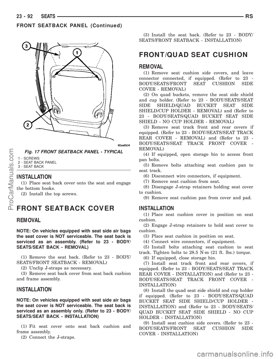
INSTALLATION
(1) Place seat back cover onto the seat and engage
the bottom hooks.
(2) Install the top screws.
FRONT SEATBACK COVER
REMOVAL
NOTE: On vehicles equipped with seat side air bags
the seat cover is NOT serviceable. The seat back is
serviced as an assembly. (Refer to 23 - BODY/
SEATS/SEAT BACK - REMOVAL)
(1) Remove the seat back. (Refer to 23 - BODY/
SEATS/FRONT SEATBACK - REMOVAL)
(2) Unclip J-straps as necessary.
(3) Remove seat back cover from seat back cushion
and frame assembly.
INSTALLATION
NOTE: On vehicles equipped with seat side air bags
the seat cover is NOT serviceable. The seat back is
serviced as an assembly only. (Refer to 23 - BODY/
SEATS/SEAT BACK - INSTALLATION)
(1) Fit seat cover onto seat back cushion and
frame assembly.
(2) Connect the J-straps.(3) Install the seat back. (Refer to 23 - BODY/
SEATS/FRONT SEATBACK - INSTALLATION)
FRONT/QUAD SEAT CUSHION
REMOVAL
(1) Remove seat cushion side covers, and leave
connector connected, if equipped. (Refer to 23 -
BODY/SEATS/FRONT SEAT CUSHION SIDE
COVER - REMOVAL)
(2) On quad buckets, remove the seat side shield
and cup holder. (Refer to 23 - BODY/SEATS/SEAT
SIDE SHIELD/QUAD BUCKET SEAT SIDE
SHIELD/CUP HOLDER - REMOVAL) and (Refer to
23 - BODY/SEATS/QUAD BUCKET SEAT SIDE
SHIELD - NO CUP HOLDER - REMOVAL)
(3) Remove seat track front and rear covers if
equipped. (Refer to 23 - BODY/SEATS/SEAT TRACK
REAR COVER - REMOVAL) and (Refer to 23 -
BODY/SEATS/SEAT TRACK FRONT COVER -
REMOVAL)
(4) If equipped, open storage bin to access front
pan bolts.
(5) Remove bolts attaching seat cushion pan to
seat track.
(6) Disconnect wire connectors, if equipment.
(7) Remove seat cushion from seat.
(8) Disengage J-strap retainers holding seat cover
to cushion.
(9) Remove seat cushion pan from cover and pad.
INSTALLATION
(1) Place seat cushion cover in position on seat
cushion.
(2) Engage J-strap retainers to hold seat cover to
cushion.
(3) Place seat cushion in position on seat.
(4) Connect wire connectors, if equipment.
(5) Install bolts attaching seat cushion to seat
track. Tighten bolts to 28.5 N´m (21 ft. lbs.) torque.
(6) If equipped, close storage bin.
(7) Install seat track front and rear covers, if
equipped. (Refer to 23 - BODY/SEATS/SEAT TRACK
REAR COVER - INSTALLATION) and (Refer to 23 -
BODY/SEATS/SEAT TRACK FRONT COVER -
INSTALLATION)
(8) Install the quad seat side shield and cup holder
if equipped. (Refer to 23 - BODY/SEATS/QUAD
BUCKET SEAT SIDE SHIELD/CUP HOLDER -
INSTALLATION) and (Refer to 23 - BODY/SEATS/
QUAD BUCKET SEAT SIDE SHIELD - NO CUP
HOLDER - INSTALLATION)
(9) Install seat cushion side covers. (Refer to 23 -
BODY/SEATS/FRONT SEAT CUSHION SIDE
COVER - INSTALLATION)
Fig. 17 FRONT SEATBACK PANEL - TYPICAL
1 - SCREWS
2 - SEAT BACK PANEL
3 - SEAT BACK
23 - 92 SEATSRS
FRONT SEATBACK PANEL (Continued)
ProCarManuals.com