2003 CHRYSLER CARAVAN oil change
[x] Cancel search: oil changePage 983 of 2177

Component Page
C313 (Rear Console)................. 8W-80-39
C313 (Rear Console)................. 8W-80-39
C314 (Highline).................... 8W-80-40
C314 (Highline).................... 8W-80-40
C315 (Highline).................... 8W-80-41
C315 (Highline).................... 8W-80-41
C316 (Power Sliding Door)............ 8W-80-41
C316 (Power Sliding Door)............ 8W-80-42
C317 (Power Sliding Door)............ 8W-80-42
C317 (Power Sliding Door)............ 8W-80-42
C318 (Trailer Tow).................. 8W-80-43
C318 (Trailer Tow).................. 8W-80-43
C319 (Lowline)..................... 8W-80-43
C319 (Lowline)..................... 8W-80-44
C320............................. 8W-80-44
C320............................. 8W-80-44
C321............................. 8W-80-44
C321............................. 8W-80-45
C322 (Memory)..................... 8W-80-45
C322 (Memory)..................... 8W-80-45
C324 (Manual Sliding Door)........... 8W-80-46
C324 (Manual Sliding Door)........... 8W-80-46
C325 (Manual Sliding Door)........... 8W-80-46
C325 (Manual Sliding Door)........... 8W-80-46
C326............................. 8W-80-46
C326............................. 8W-80-47
C327............................. 8W-80-47
C327............................. 8W-80-47
C328 (Sunroof)..................... 8W-80-47
C328 (Sunroof)..................... 8W-80-47
C329 (Diesel)...................... 8W-80-48
C329 (Diesel)...................... 8W-80-48
C330 (Diesel)...................... 8W-80-48
C330 (Diesel)...................... 8W-80-48
C331 (Diesel)...................... 8W-80-48
C331 (Diesel)...................... 8W-80-49
C332 (3 Zone ATC).................. 8W-80-49
C332 (3 Zone ATC).................. 8W-80-49
Cabin Heater Assist C1 (Diesel)........ 8W-80-50
Cabin Heater Assist C2 (Diesel)........ 8W-80-50
Camshaft Position Sensor (Diesel)...... 8W-80-50
Camshaft Position Sensor (Gas)........ 8W-80-50
CD Changer....................... 8W-80-51
Center Dome Lamp (Base/Highline)..... 8W-80-51
Center High Mounted Stop Lamp....... 8W-80-51
Clockspring C1..................... 8W-80-51
Clockspring C2..................... 8W-80-52
Clockspring C3..................... 8W-80-52
Clockspring C4..................... 8W-80-52
Clutch Pedal Interlock Switch (MTX).... 8W-80-52
Clutch Pedal Upstop Switch (Diesel).... 8W-80-52
Controller Antilock Brake............. 8W-80-53
Crank Case Ventilation Heater (Diesel) . . 8W-80-53
Crankshaft Position Sensor (Diesel)..... 8W-80-53Component Page
Crankshaft Position Sensor (Gas)....... 8W-80-54
Data Link Connector................ 8W-80-54
Dosing Pump (Diesel)................ 8W-80-54
Driver Airbag Squib 1................ 8W-80-55
Driver Airbag Squib 2................ 8W-80-55
Driver Blend Door Actuator (ATC)...... 8W-80-55
Driver Blend Door Actuator (MTC)...... 8W-80-55
Driver Door Courtesy Lamp........... 8W-80-56
Driver Door Lock Switch............. 8W-80-56
Driver Heated Seat Back............. 8W-80-56
Driver Heated Seat Cushion........... 8W-80-56
Driver Heated Seat Module C1......... 8W-80-56
Driver Heated Seat Module C2......... 8W-80-57
Driver Heated Seat Module C3......... 8W-80-57
Driver Power Seat Front Riser Motor.... 8W-80-57
Driver Power Seat Front Riser Position
Sensor......................... 8W-80-57
Driver Power Seat Horizontal Motor.... 8W-80-58
Driver Power Seat Horizontal Position
Sensor......................... 8W-80-58
Driver Power Seat Rear Riser Motor.... 8W-80-58
Driver Power Seat Rear Riser Position
Sensor......................... 8W-80-58
Driver Power Seat Recliner Motor...... 8W-80-58
Driver Power Seat Recliner Position
Sensor......................... 8W-80-59
Driver Power Seat Switch............ 8W-80-59
Driver Power Window Motor.......... 8W-80-59
Driver Power Window Switch
(LHD Except Lowline)............. 8W-80-60
Driver Power Window Switch (LHD
Lowline)........................ 8W-80-60
Driver Power Window Switch (RHD).... 8W-80-60
Driver Seat Belt Switch.............. 8W-80-61
Driver Seat Belt Tensioner............ 8W-80-61
DVD Screen....................... 8W-80-61
DVD/CD Changer C1................ 8W-80-61
DVD/CD Changer C2................ 8W-80-62
DVD/CD Changer C3................ 8W-80-62
EGR Solenoid (3.3L/3.8L Export)....... 8W-80-62
EGR Solenoid (Diesel)............... 8W-80-62
Engine Control Module C1 (Diesel)..... 8W-80-63
Engine Control Module C2 (Diesel)..... 8W-80-64
Engine Coolant Temp Sensor (Diesel).... 8W-80-65
Engine Coolant Temp Sensor (Gas)..... 8W-80-65
Engine Oil Pressure Sensor (Diesel)..... 8W-80-66
Engine Oil Pressure Switch (Gas)...... 8W-80-66
EVAP/Purge Solenoid (Gas)........... 8W-80-66
Evaporator Temperature Sensor........ 8W-80-66
Floor Console Lamp................. 8W-80-67
Floor Console Power Outlet........... 8W-80-67
Front Blower Module C1 (ATC)........ 8W-80-67
Front Blower Module C2 (ATC)........ 8W-80-67
Front Cigar Lighter................. 8W-80-68
8W - 80 - 2 8W-80 CONNECTOR PIN-OUTSRS
ProCarManuals.com
Page 1181 of 2177
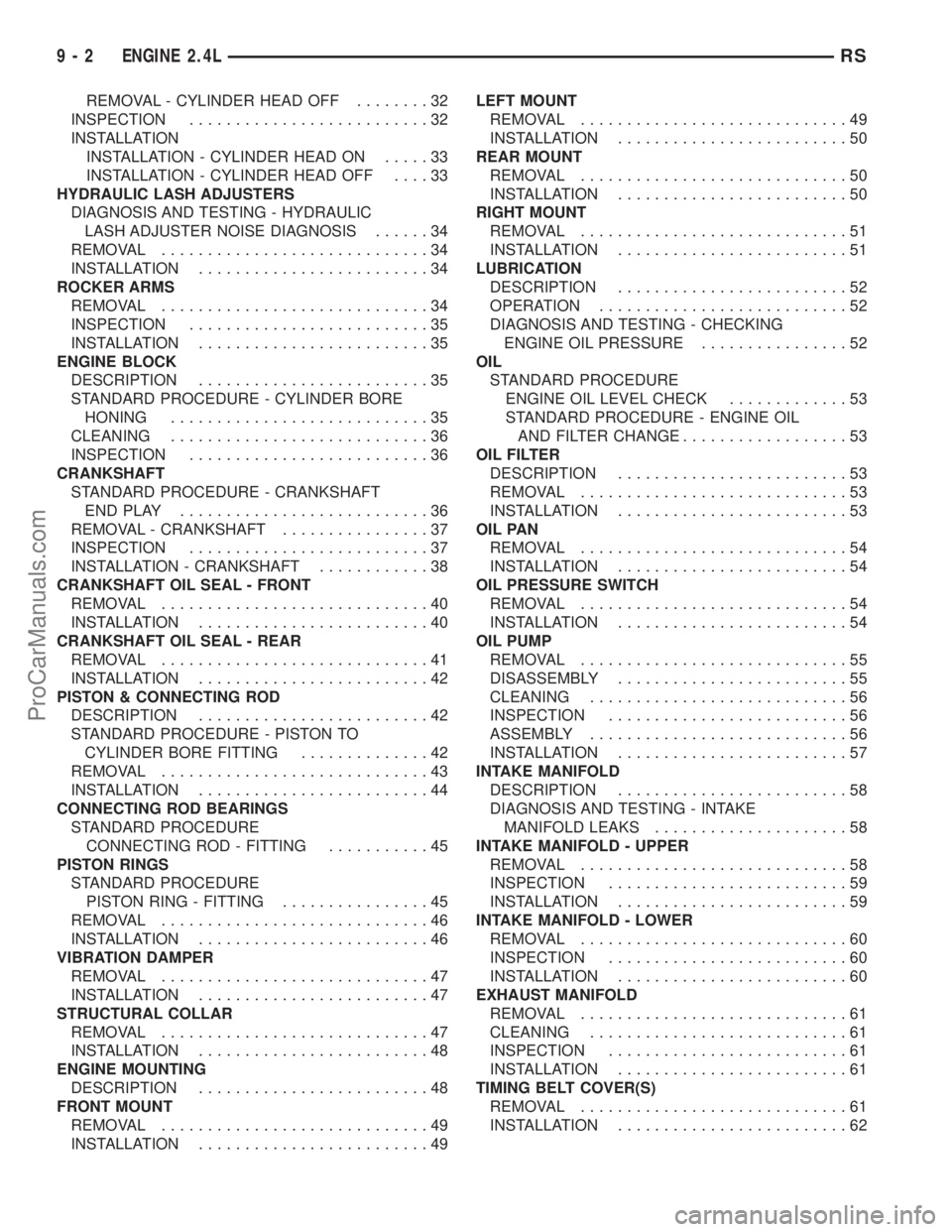
REMOVAL - CYLINDER HEAD OFF........32
INSPECTION..........................32
INSTALLATION
INSTALLATION - CYLINDER HEAD ON.....33
INSTALLATION - CYLINDER HEAD OFF....33
HYDRAULIC LASH ADJUSTERS
DIAGNOSIS AND TESTING - HYDRAULIC
LASH ADJUSTER NOISE DIAGNOSIS......34
REMOVAL.............................34
INSTALLATION.........................34
ROCKER ARMS
REMOVAL.............................34
INSPECTION..........................35
INSTALLATION.........................35
ENGINE BLOCK
DESCRIPTION.........................35
STANDARD PROCEDURE - CYLINDER BORE
HONING............................35
CLEANING............................36
INSPECTION..........................36
CRANKSHAFT
STANDARD PROCEDURE - CRANKSHAFT
ENDPLAY ...........................36
REMOVAL - CRANKSHAFT................37
INSPECTION..........................37
INSTALLATION - CRANKSHAFT............38
CRANKSHAFT OIL SEAL - FRONT
REMOVAL.............................40
INSTALLATION.........................40
CRANKSHAFT OIL SEAL - REAR
REMOVAL.............................41
INSTALLATION.........................42
PISTON & CONNECTING ROD
DESCRIPTION.........................42
STANDARD PROCEDURE - PISTON TO
CYLINDER BORE FITTING..............42
REMOVAL.............................43
INSTALLATION.........................44
CONNECTING ROD BEARINGS
STANDARD PROCEDURE
CONNECTING ROD - FITTING...........45
PISTON RINGS
STANDARD PROCEDURE
PISTON RING - FITTING................45
REMOVAL.............................46
INSTALLATION.........................46
VIBRATION DAMPER
REMOVAL.............................47
INSTALLATION.........................47
STRUCTURAL COLLAR
REMOVAL.............................47
INSTALLATION.........................48
ENGINE MOUNTING
DESCRIPTION.........................48
FRONT MOUNT
REMOVAL.............................49
INSTALLATION.........................49LEFT MOUNT
REMOVAL.............................49
INSTALLATION.........................50
REAR MOUNT
REMOVAL.............................50
INSTALLATION.........................50
RIGHT MOUNT
REMOVAL.............................51
INSTALLATION.........................51
LUBRICATION
DESCRIPTION.........................52
OPERATION...........................52
DIAGNOSIS AND TESTING - CHECKING
ENGINE OIL PRESSURE................52
OIL
STANDARD PROCEDURE
ENGINE OIL LEVEL CHECK.............53
STANDARD PROCEDURE - ENGINE OIL
AND FILTER CHANGE..................53
OIL FILTER
DESCRIPTION.........................53
REMOVAL.............................53
INSTALLATION.........................53
OIL PAN
REMOVAL.............................54
INSTALLATION.........................54
OIL PRESSURE SWITCH
REMOVAL.............................54
INSTALLATION.........................54
OIL PUMP
REMOVAL.............................55
DISASSEMBLY.........................55
CLEANING............................56
INSPECTION..........................56
ASSEMBLY............................56
INSTALLATION.........................57
INTAKE MANIFOLD
DESCRIPTION.........................58
DIAGNOSIS AND TESTING - INTAKE
MANIFOLD LEAKS.....................58
INTAKE MANIFOLD - UPPER
REMOVAL.............................58
INSPECTION..........................59
INSTALLATION.........................59
INTAKE MANIFOLD - LOWER
REMOVAL.............................60
INSPECTION..........................60
INSTALLATION.........................60
EXHAUST MANIFOLD
REMOVAL.............................61
CLEANING............................61
INSPECTION..........................61
INSTALLATION.........................61
TIMING BELT COVER(S)
REMOVAL.............................61
INSTALLATION.........................62
9 - 2 ENGINE 2.4LRS
ProCarManuals.com
Page 1185 of 2177
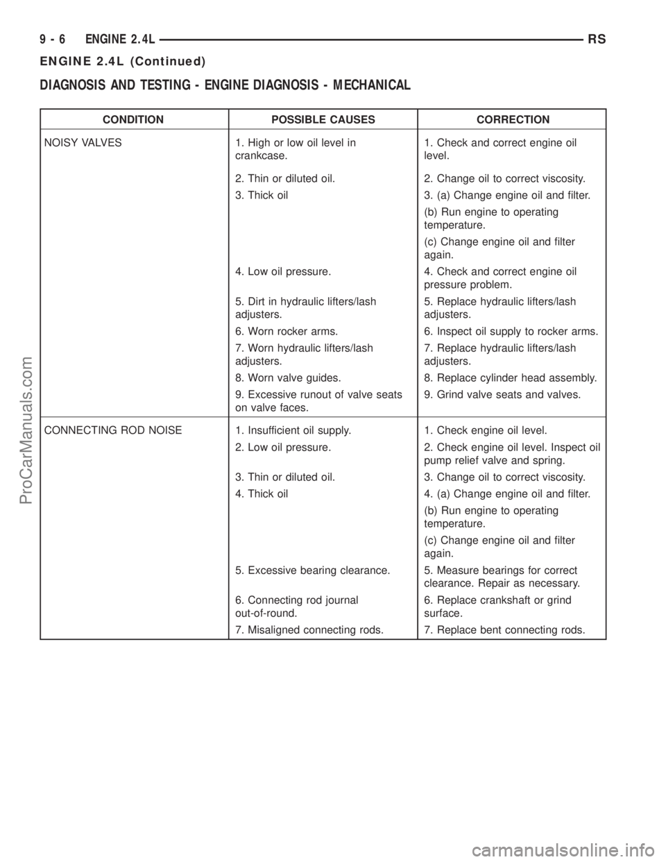
DIAGNOSIS AND TESTING - ENGINE DIAGNOSIS - MECHANICAL
CONDITION POSSIBLE CAUSES CORRECTION
NOISY VALVES 1. High or low oil level in
crankcase.1. Check and correct engine oil
level.
2. Thin or diluted oil. 2. Change oil to correct viscosity.
3. Thick oil 3. (a) Change engine oil and filter.
(b) Run engine to operating
temperature.
(c) Change engine oil and filter
again.
4. Low oil pressure. 4. Check and correct engine oil
pressure problem.
5. Dirt in hydraulic lifters/lash
adjusters.5. Replace hydraulic lifters/lash
adjusters.
6. Worn rocker arms. 6. Inspect oil supply to rocker arms.
7. Worn hydraulic lifters/lash
adjusters.7. Replace hydraulic lifters/lash
adjusters.
8. Worn valve guides. 8. Replace cylinder head assembly.
9. Excessive runout of valve seats
on valve faces.9. Grind valve seats and valves.
CONNECTING ROD NOISE 1. Insufficient oil supply. 1. Check engine oil level.
2. Low oil pressure. 2. Check engine oil level. Inspect oil
pump relief valve and spring.
3. Thin or diluted oil. 3. Change oil to correct viscosity.
4. Thick oil 4. (a) Change engine oil and filter.
(b) Run engine to operating
temperature.
(c) Change engine oil and filter
again.
5. Excessive bearing clearance. 5. Measure bearings for correct
clearance. Repair as necessary.
6. Connecting rod journal
out-of-round.6. Replace crankshaft or grind
surface.
7. Misaligned connecting rods. 7. Replace bent connecting rods.
9 - 6 ENGINE 2.4LRS
ENGINE 2.4L (Continued)
ProCarManuals.com
Page 1186 of 2177
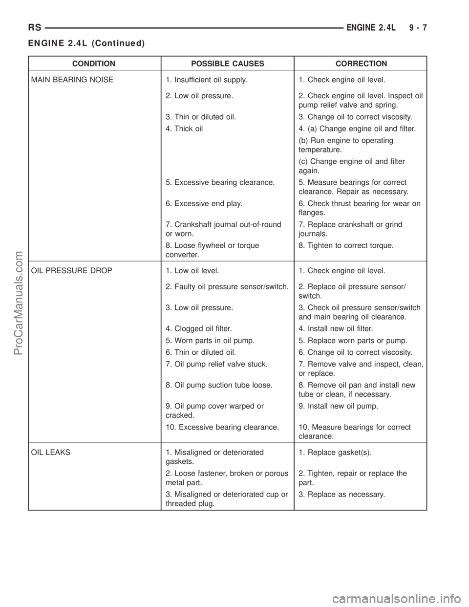
CONDITION POSSIBLE CAUSES CORRECTION
MAIN BEARING NOISE 1. Insufficient oil supply. 1. Check engine oil level.
2. Low oil pressure. 2. Check engine oil level. Inspect oil
pump relief valve and spring.
3. Thin or diluted oil. 3. Change oil to correct viscosity.
4. Thick oil 4. (a) Change engine oil and filter.
(b) Run engine to operating
temperature.
(c) Change engine oil and filter
again.
5. Excessive bearing clearance. 5. Measure bearings for correct
clearance. Repair as necessary.
6. Excessive end play. 6. Check thrust bearing for wear on
flanges.
7. Crankshaft journal out-of-round
or worn.7. Replace crankshaft or grind
journals.
8. Loose flywheel or torque
converter.8. Tighten to correct torque.
OIL PRESSURE DROP 1. Low oil level. 1. Check engine oil level.
2. Faulty oil pressure sensor/switch. 2. Replace oil pressure sensor/
switch.
3. Low oil pressure. 3. Check oil pressure sensor/switch
and main bearing oil clearance.
4. Clogged oil filter. 4. Install new oil filter.
5. Worn parts in oil pump. 5. Replace worn parts or pump.
6. Thin or diluted oil. 6. Change oil to correct viscosity.
7. Oil pump relief valve stuck. 7. Remove valve and inspect, clean,
or replace.
8. Oil pump suction tube loose. 8. Remove oil pan and install new
tube or clean, if necessary.
9. Oil pump cover warped or
cracked.9. Install new oil pump.
10. Excessive bearing clearance. 10. Measure bearings for correct
clearance.
OIL LEAKS 1. Misaligned or deteriorated
gaskets.1. Replace gasket(s).
2. Loose fastener, broken or porous
metal part.2. Tighten, repair or replace the
part.
3. Misaligned or deteriorated cup or
threaded plug.3. Replace as necessary.
RSENGINE 2.4L9-7
ENGINE 2.4L (Continued)
ProCarManuals.com
Page 1208 of 2177
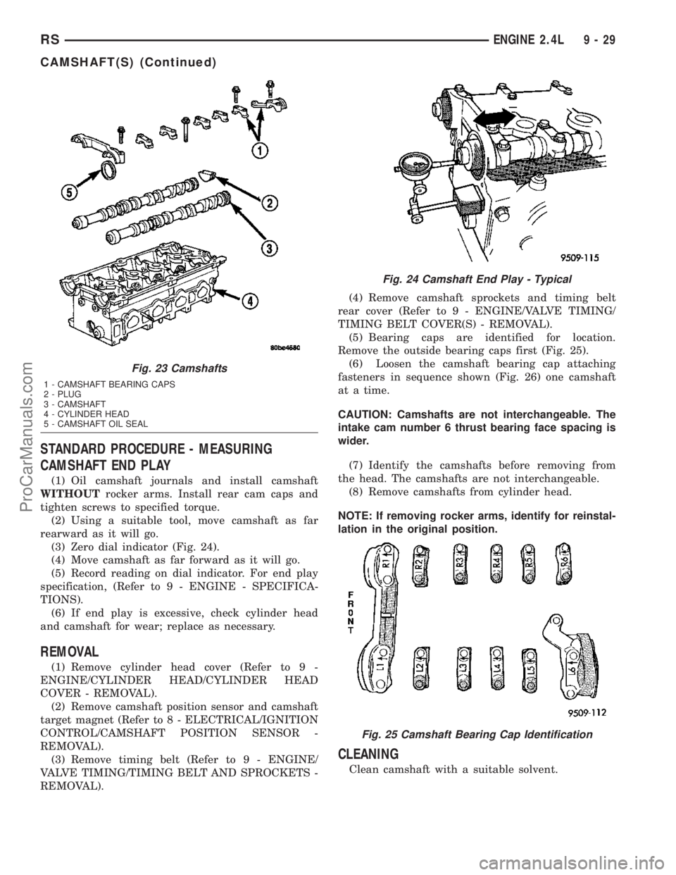
STANDARD PROCEDURE - MEASURING
CAMSHAFT END PLAY
(1) Oil camshaft journals and install camshaft
WITHOUTrocker arms. Install rear cam caps and
tighten screws to specified torque.
(2) Using a suitable tool, move camshaft as far
rearward as it will go.
(3) Zero dial indicator (Fig. 24).
(4) Move camshaft as far forward as it will go.
(5) Record reading on dial indicator. For end play
specification, (Refer to 9 - ENGINE - SPECIFICA-
TIONS).
(6) If end play is excessive, check cylinder head
and camshaft for wear; replace as necessary.
REMOVAL
(1) Remove cylinder head cover (Refer to 9 -
ENGINE/CYLINDER HEAD/CYLINDER HEAD
COVER - REMOVAL).
(2) Remove camshaft position sensor and camshaft
target magnet (Refer to 8 - ELECTRICAL/IGNITION
CONTROL/CAMSHAFT POSITION SENSOR -
REMOVAL).
(3) Remove timing belt (Refer to 9 - ENGINE/
VALVE TIMING/TIMING BELT AND SPROCKETS -
REMOVAL).(4) Remove camshaft sprockets and timing belt
rear cover (Refer to 9 - ENGINE/VALVE TIMING/
TIMING BELT COVER(S) - REMOVAL).
(5) Bearing caps are identified for location.
Remove the outside bearing caps first (Fig. 25).
(6) Loosen the camshaft bearing cap attaching
fasteners in sequence shown (Fig. 26) one camshaft
at a time.
CAUTION: Camshafts are not interchangeable. The
intake cam number 6 thrust bearing face spacing is
wider.
(7) Identify the camshafts before removing from
the head. The camshafts are not interchangeable.
(8) Remove camshafts from cylinder head.
NOTE: If removing rocker arms, identify for reinstal-
lation in the original position.
CLEANING
Clean camshaft with a suitable solvent.
Fig. 23 Camshafts
1 - CAMSHAFT BEARING CAPS
2 - PLUG
3 - CAMSHAFT
4 - CYLINDER HEAD
5 - CAMSHAFT OIL SEAL
Fig. 24 Camshaft End Play - Typical
Fig. 25 Camshaft Bearing Cap Identification
RSENGINE 2.4L9-29
CAMSHAFT(S) (Continued)
ProCarManuals.com
Page 1217 of 2177
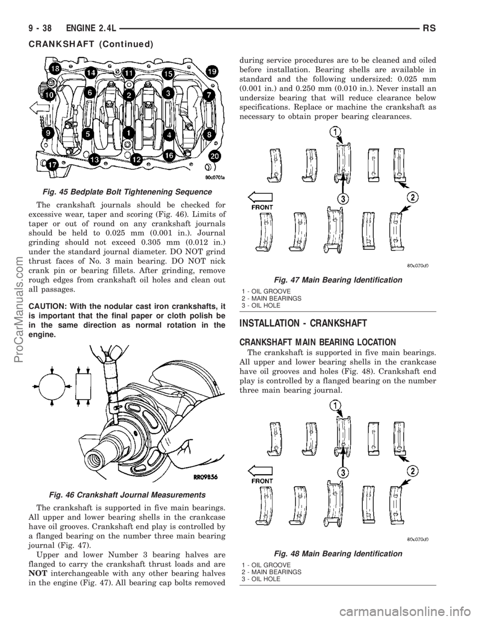
The crankshaft journals should be checked for
excessive wear, taper and scoring (Fig. 46). Limits of
taper or out of round on any crankshaft journals
should be held to 0.025 mm (0.001 in.). Journal
grinding should not exceed 0.305 mm (0.012 in.)
under the standard journal diameter. DO NOT grind
thrust faces of No. 3 main bearing. DO NOT nick
crank pin or bearing fillets. After grinding, remove
rough edges from crankshaft oil holes and clean out
all passages.
CAUTION: With the nodular cast iron crankshafts, it
is important that the final paper or cloth polish be
in the same direction as normal rotation in the
engine.
The crankshaft is supported in five main bearings.
All upper and lower bearing shells in the crankcase
have oil grooves. Crankshaft end play is controlled by
a flanged bearing on the number three main bearing
journal (Fig. 47).
Upper and lower Number 3 bearing halves are
flanged to carry the crankshaft thrust loads and are
NOTinterchangeable with any other bearing halves
in the engine (Fig. 47). All bearing cap bolts removedduring service procedures are to be cleaned and oiled
before installation. Bearing shells are available in
standard and the following undersized: 0.025 mm
(0.001 in.) and 0.250 mm (0.010 in.). Never install an
undersize bearing that will reduce clearance below
specifications. Replace or machine the crankshaft as
necessary to obtain proper bearing clearances.
INSTALLATION - CRANKSHAFT
CRANKSHAFT MAIN BEARING LOCATION
The crankshaft is supported in five main bearings.
All upper and lower bearing shells in the crankcase
have oil grooves and holes (Fig. 48). Crankshaft end
play is controlled by a flanged bearing on the number
three main bearing journal.
Fig. 45 Bedplate Bolt Tightenening Sequence
Fig. 46 Crankshaft Journal Measurements
Fig. 47 Main Bearing Identification
1 - OIL GROOVE
2 - MAIN BEARINGS
3 - OIL HOLE
Fig. 48 Main Bearing Identification
1 - OIL GROOVE
2 - MAIN BEARINGS
3 - OIL HOLE
9 - 38 ENGINE 2.4LRS
CRANKSHAFT (Continued)
ProCarManuals.com
Page 1223 of 2177
(6) Pistons and connecting rods must be removed
from top of cylinder block. Rotate crankshaft so that
each connecting rod is centered in cylinder bore.
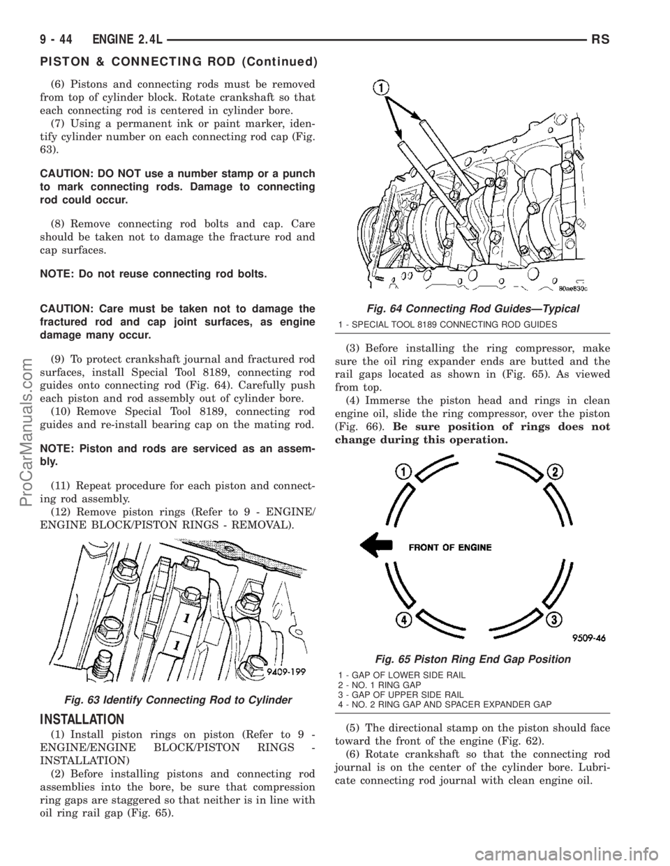
(7) Using a permanent ink or paint marker, iden-
tify cylinder number on each connecting rod cap (Fig.
63).
CAUTION: DO NOT use a number stamp or a punch
to mark connecting rods. Damage to connecting
rod could occur.
(8) Remove connecting rod bolts and cap. Care
should be taken not to damage the fracture rod and
cap surfaces.
NOTE: Do not reuse connecting rod bolts.
CAUTION: Care must be taken not to damage the
fractured rod and cap joint surfaces, as engine
damage many occur.
(9) To protect crankshaft journal and fractured rod
surfaces, install Special Tool 8189, connecting rod
guides onto connecting rod (Fig. 64). Carefully push
each piston and rod assembly out of cylinder bore.
(10) Remove Special Tool 8189, connecting rod
guides and re-install bearing cap on the mating rod.
NOTE: Piston and rods are serviced as an assem-
bly.
(11) Repeat procedure for each piston and connect-
ing rod assembly.
(12) Remove piston rings (Refer to 9 - ENGINE/
ENGINE BLOCK/PISTON RINGS - REMOVAL).
INSTALLATION
(1) Install piston rings on piston (Refer to 9 -
ENGINE/ENGINE BLOCK/PISTON RINGS -
INSTALLATION)
(2) Before installing pistons and connecting rod
assemblies into the bore, be sure that compression
ring gaps are staggered so that neither is in line with
oil ring rail gap (Fig. 65).(3) Before installing the ring compressor, make
sure the oil ring expander ends are butted and the
rail gaps located as shown in (Fig. 65). As viewed
from top.
(4) Immerse the piston head and rings in clean
engine oil, slide the ring compressor, over the piston
(Fig. 66).Be sure position of rings does not
change during this operation.
(5) The directional stamp on the piston should face
toward the front of the engine (Fig. 62).
(6) Rotate crankshaft so that the connecting rod
journal is on the center of the cylinder bore. Lubri-
cate connecting rod journal with clean engine oil.
Fig. 63 Identify Connecting Rod to Cylinder
Fig. 64 Connecting Rod GuidesÐTypical
1 - SPECIAL TOOL 8189 CONNECTING ROD GUIDES
Fig. 65 Piston Ring End Gap Position
1 - GAP OF LOWER SIDE RAIL
2 - NO. 1 RING GAP
3 - GAP OF UPPER SIDE RAIL
4 - NO. 2 RING GAP AND SPACER EXPANDER GAP
9 - 44 ENGINE 2.4LRS
PISTON & CONNECTING ROD (Continued)
ProCarManuals.com
Page 1232 of 2177
OIL
STANDARD PROCEDURE
ENGINE OIL LEVEL CHECK
The best time to check engine oil level is after it
has sat overnight, or if the engine has been running,
allow the engine to be shut off for at least 5 minutes
before checking oil level.
Checking the oil while the vehicle is on level
ground will improve the accuracy of the oil level
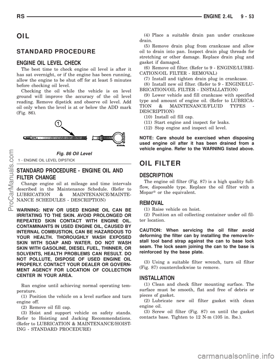
reading. Remove dipstick and observe oil level. Add
oil only when the level is at or below the ADD mark
(Fig. 86).
STANDARD PROCEDURE - ENGINE OIL AND
FILTER CHANGE
Change engine oil at mileage and time intervals
described in the Maintenance Schedule. (Refer to
LUBRICATION & MAINTENANCE/MAINTE-
NANCE SCHEDULES - DESCRIPTION)
WARNING: NEW OR USED ENGINE OIL CAN BE
IRRITATING TO THE SKIN. AVOID PROLONGED OR
REPEATED SKIN CONTACT WITH ENGINE OIL.
CONTAMINANTS IN USED ENGINE OIL, CAUSED BY
INTERNAL COMBUSTION, CAN BE HAZARDOUS TO
YOUR HEALTH. THOROUGHLY WASH EXPOSED
SKIN WITH SOAP AND WATER. DO NOT WASH
SKIN WITH GASOLINE, DIESEL FUEL, THINNER, OR
SOLVENTS, HEALTH PROBLEMS CAN RESULT. DO
NOT POLLUTE, DISPOSE OF USED ENGINE OIL
PROPERLY. CONTACT YOUR DEALER OR GOVERN-
MENT AGENCY FOR LOCATION OF COLLECTION
CENTER IN YOUR AREA.
Run engine until achieving normal operating tem-
perature.
(1) Position the vehicle on a level surface and turn
engine off.
(2) Remove oil fill cap.
(3) Hoist and support vehicle on safety stands.
Refer to Hoisting and Jacking Recommendations.
(Refer to LUBRICATION & MAINTENANCE/HOIST-
ING - STANDARD PROCEDURE)(4) Place a suitable drain pan under crankcase
drain.
(5) Remove drain plug from crankcase and allow
oil to drain into pan. Inspect drain plug threads for
stretching or other damage. Replace drain plug and
gasket if damaged.
(6) Remove oil filter. (Refer to 9 - ENGINE/LUBRI-
CATION/OIL FILTER - REMOVAL)
(7) Install and tighten drain plug in crankcase.
(8) Install new oil filter. (Refer to 9 - ENGINE/LU-
BRICATION/OIL FILTER - INSTALLATION)
(9) Lower vehicle and fill crankcase with specified
type and amount of engine oil. (Refer to LUBRICA-
TION & MAINTENANCE/FLUID TYPES -
DESCRIPTION)
(10) Install oil fill cap.
(11) Start engine and inspect for leaks.
(12) Stop engine and inspect oil level.
NOTE: Care should be exercised when disposing
used engine oil after it has been drained from a
vehicle engine. Refer to the WARNING listed above.
OIL FILTER
DESCRIPTION
The engine oil filter (Fig. 87) is a high quality full-
flow, disposable type. Replace the oil filter with a
Mopartor the equivalent.
REMOVAL
(1) Raise vehicle on hoist.
(2) Position an oil collecting container under oil fil-
ter location.
CAUTION: When servicing the oil filter avoid
deforming the filter can by installing the remove/in-
stall tool band strap against the can to base lock
seam. The lock seam joining the can to the base is
reinforced by the base plate.
(3) Using a suitable filter wrench, turn oil filter
(Fig. 87) counterclockwise to remove.
INSTALLATION
(1) Clean and check filter mounting surface. The
surface must be smooth, flat and free of debris or
pieces of gasket.
(2) Lubricate new oil filter gasket with clean
engine oil.
(3) Screw oil filter (Fig. 87) on until the gasket
contacts base. Tighten to 12 N´m (105 in. lbs.).
Fig. 86 Oil Level
1 - ENGINE OIL LEVEL DIPSTICK
RSENGINE 2.4L9-53
ProCarManuals.com