2003 CHRYSLER CARAVAN torque
[x] Cancel search: torquePage 1752 of 2177
INSTALLATION
NOTE: The screws attaching the door latch to the
door end frame have nylon patches on the threads.
All screws must be replaced when the latch has
been removed.
(1) Insert inside handle latch link to door latch
and engage clip (Fig. 8).
(2) Place door latch in position on door end frame.
(3) Install screws attaching door latch to door end
frame. Tighten screws to 10 N´m (90 in. lbs.) torque
(Fig. 9).
(4) Insert other linkages to door latch and engage
clips.
(5) Connect wire connector into power door lock
motor, if equipped.
(6) Insert a hex wrench through the elongated hole
located in the door shut face above the latch.
(7) Loosen allen head screw.
(8) Pull outward on the outside door handle and
release.
(9) Tighten allen head screw.
(10) Verify door latch and power door lock opera-
tion.
(11) Install watershield and front door trim panel.
LATCH STRIKER
REMOVAL
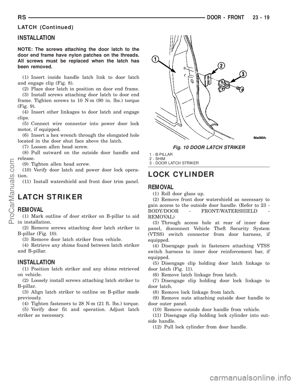
(1) Mark outline of door striker on B-pillar to aid
in installation.
(2) Remove screws attaching door latch striker to
B-pillar (Fig. 10).
(3) Remove door latch striker from vehicle.
(4) Retrieve any shims found between latch striker
and B-pillar.
INSTALLATION
(1) Position latch striker and any shims retrieved
on vehicle.
(2) Loosely install screws attaching latch striker to
B-pillar.
(3) Align latch striker to outline on B-pillar made
previously.
(4) Tighten fasteners to 28 N´m (21 ft. lbs.) torque.
(5) Verify door fit and operation. Adjust latch
striker as necessary.
LOCK CYLINDER
REMOVAL
(1) Roll door glass up.
(2) Remove front door watershield as necessary to
gain access to the outside door handle. (Refer to 23 -
BODY/DOOR - FRONT/WATERSHIELD -
REMOVAL)
(3) Through access hole at rear of inner door
panel, disconnect Vehicle Theft Security System
(VTSS) switch connector from door harness, if
equipped.
(4) Disengage push in fasteners attaching VTSS
switch harness to inner door reinforcement bar, if
equipped.
(5) Disengage clip holding door latch linkage to
door latch (Fig. 11).
(6) Remove latch linkage from latch.
(7) Disengage clip holding door lock linkage to
door latch.
(8) Remove lock linkage from latch.
(9) Remove nuts attaching outside door handle to
door outer panel.
(10) Remove outside door handle from vehicle.
(11) Disengage clip holding lock cylinder into out-
side handle.
(12) Pull lock cylinder from door handle.
Fig. 10 DOOR LATCH STRIKER
1 - B-PILLAR
2 - SHIM
3 - DOOR LATCH STRIKER
RSDOOR - FRONT23-19
LATCH (Continued)
ProCarManuals.com
Page 1758 of 2177
(2) Roll center hinge forward in roller channel.
(3) Place center hinge in position on sliding door
and align marks.
(4) Install bolts attaching center hinge to sliding
door.
(5) Verify sliding door alignment and operation.
SLIDING DOOR STOP BUMPER
BEZEL
REMOVAL
(1) Using a trim stick (C-4755), disengage clips
attaching door stop bumper bezel to the door trim
panel.
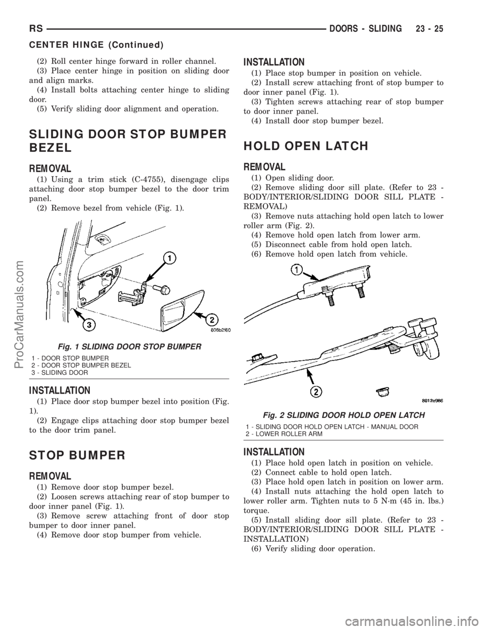
(2) Remove bezel from vehicle (Fig. 1).
INSTALLATION
(1) Place door stop bumper bezel into position (Fig.
1).
(2) Engage clips attaching door stop bumper bezel
to the door trim panel.
STOP BUMPER
REMOVAL
(1) Remove door stop bumper bezel.
(2) Loosen screws attaching rear of stop bumper to
door inner panel (Fig. 1).
(3) Remove screw attaching front of door stop
bumper to door inner panel.
(4) Remove door stop bumper from vehicle.
INSTALLATION
(1) Place stop bumper in position on vehicle.
(2) Install screw attaching front of stop bumper to
door inner panel (Fig. 1).
(3) Tighten screws attaching rear of stop bumper
to door inner panel.
(4) Install door stop bumper bezel.
HOLD OPEN LATCH
REMOVAL
(1) Open sliding door.
(2) Remove sliding door sill plate. (Refer to 23 -
BODY/INTERIOR/SLIDING DOOR SILL PLATE -
REMOVAL)
(3) Remove nuts attaching hold open latch to lower
roller arm (Fig. 2).
(4) Remove hold open latch from lower arm.
(5) Disconnect cable from hold open latch.
(6) Remove hold open latch from vehicle.
INSTALLATION
(1) Place hold open latch in position on vehicle.
(2) Connect cable to hold open latch.
(3) Place hold open latch in position on lower arm.
(4) Install nuts attaching the hold open latch to
lower roller arm. Tighten nuts to 5 N´m (45 in. lbs.)
torque.
(5) Install sliding door sill plate. (Refer to 23 -
BODY/INTERIOR/SLIDING DOOR SILL PLATE -
INSTALLATION)
(6) Verify sliding door operation.
Fig. 1 SLIDING DOOR STOP BUMPER
1 - DOOR STOP BUMPER
2 - DOOR STOP BUMPER BEZEL
3 - SLIDING DOOR
Fig. 2 SLIDING DOOR HOLD OPEN LATCH
1 - SLIDING DOOR HOLD OPEN LATCH - MANUAL DOOR
2 - LOWER ROLLER ARM
RSDOORS - SLIDING23-25
CENTER HINGE (Continued)
ProCarManuals.com
Page 1761 of 2177
LOWER HINGE
REMOVAL
NOTE: For power sliding door procedures refer to
POWER SLIDING DOOR SYSTEM in the ELECTRI-
CAL section.
(1) Open sliding door.
(2) Mark outline of roller arm on sliding door to
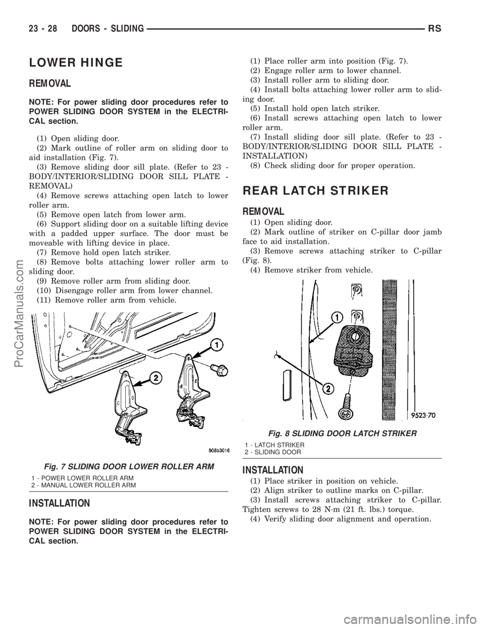
aid installation (Fig. 7).
(3) Remove sliding door sill plate. (Refer to 23 -
BODY/INTERIOR/SLIDING DOOR SILL PLATE -
REMOVAL)
(4) Remove screws attaching open latch to lower
roller arm.
(5) Remove open latch from lower arm.
(6) Support sliding door on a suitable lifting device
with a padded upper surface. The door must be
moveable with lifting device in place.
(7) Remove hold open latch striker.
(8) Remove bolts attaching lower roller arm to
sliding door.
(9) Remove roller arm from sliding door.
(10) Disengage roller arm from lower channel.
(11) Remove roller arm from vehicle.
INSTALLATION
NOTE: For power sliding door procedures refer to
POWER SLIDING DOOR SYSTEM in the ELECTRI-
CAL section.(1) Place roller arm into position (Fig. 7).
(2) Engage roller arm to lower channel.
(3) Install roller arm to sliding door.
(4) Install bolts attaching lower roller arm to slid-
ing door.
(5) Install hold open latch striker.
(6) Install screws attaching open latch to lower
roller arm.
(7) Install sliding door sill plate. (Refer to 23 -
BODY/INTERIOR/SLIDING DOOR SILL PLATE -
INSTALLATION)
(8) Check sliding door for proper operation.
REAR LATCH STRIKER
REMOVAL
(1) Open sliding door.
(2) Mark outline of striker on C-pillar door jamb
face to aid installation.
(3) Remove screws attaching striker to C-pillar
(Fig. 8).
(4) Remove striker from vehicle.
INSTALLATION
(1) Place striker in position on vehicle.
(2) Align striker to outline marks on C-pillar.
(3) Install screws attaching striker to C-pillar.
Tighten screws to 28 N´m (21 ft. lbs.) torque.
(4) Verify sliding door alignment and operation.
Fig. 7 SLIDING DOOR LOWER ROLLER ARM
1 - POWER LOWER ROLLER ARM
2 - MANUAL LOWER ROLLER ARM
Fig. 8 SLIDING DOOR LATCH STRIKER
1 - LATCH STRIKER
2 - SLIDING DOOR
23 - 28 DOORS - SLIDINGRS
ProCarManuals.com
Page 1765 of 2177
(a) Open door to mid-point of travel.
(b) Mark outline of upper roller arm on door to
assist in making adjustments.
(c) Loosen bolts attaching upper roller arm to
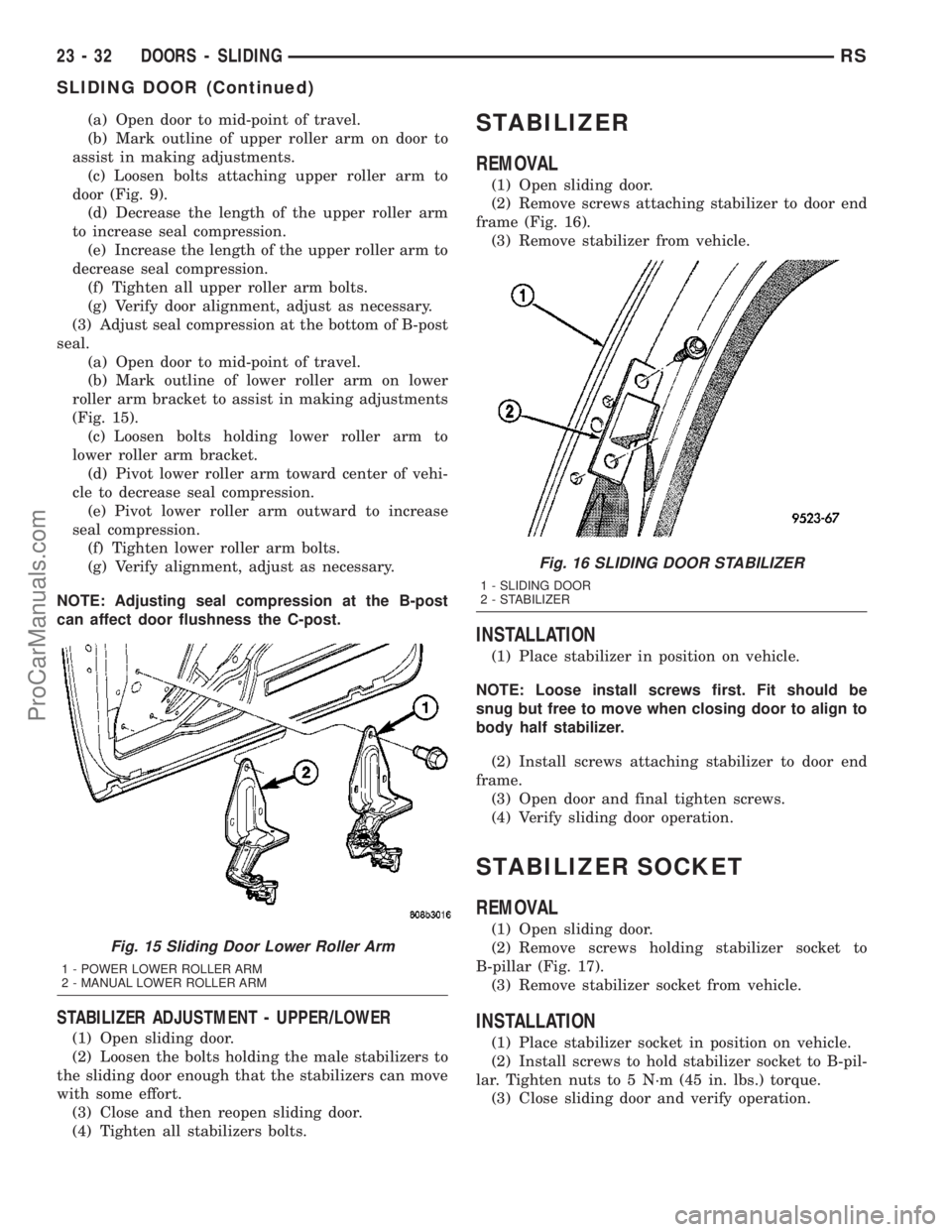
door (Fig. 9).
(d) Decrease the length of the upper roller arm
to increase seal compression.
(e) Increase the length of the upper roller arm to
decrease seal compression.
(f) Tighten all upper roller arm bolts.
(g) Verify door alignment, adjust as necessary.
(3) Adjust seal compression at the bottom of B-post
seal.
(a) Open door to mid-point of travel.
(b) Mark outline of lower roller arm on lower
roller arm bracket to assist in making adjustments
(Fig. 15).
(c) Loosen bolts holding lower roller arm to
lower roller arm bracket.
(d) Pivot lower roller arm toward center of vehi-
cle to decrease seal compression.
(e) Pivot lower roller arm outward to increase
seal compression.
(f) Tighten lower roller arm bolts.
(g) Verify alignment, adjust as necessary.
NOTE: Adjusting seal compression at the B-post
can affect door flushness the C-post.
STABILIZER ADJUSTMENT - UPPER/LOWER
(1) Open sliding door.
(2) Loosen the bolts holding the male stabilizers to
the sliding door enough that the stabilizers can move
with some effort.
(3) Close and then reopen sliding door.
(4) Tighten all stabilizers bolts.
STABILIZER
REMOVAL
(1) Open sliding door.
(2) Remove screws attaching stabilizer to door end
frame (Fig. 16).
(3) Remove stabilizer from vehicle.
INSTALLATION
(1) Place stabilizer in position on vehicle.
NOTE: Loose install screws first. Fit should be
snug but free to move when closing door to align to
body half stabilizer.
(2) Install screws attaching stabilizer to door end
frame.
(3) Open door and final tighten screws.
(4) Verify sliding door operation.
STABILIZER SOCKET
REMOVAL
(1) Open sliding door.
(2) Remove screws holding stabilizer socket to
B-pillar (Fig. 17).
(3) Remove stabilizer socket from vehicle.
INSTALLATION
(1) Place stabilizer socket in position on vehicle.
(2) Install screws to hold stabilizer socket to B-pil-
lar. Tighten nuts to 5 N´m (45 in. lbs.) torque.
(3) Close sliding door and verify operation.
Fig. 15 Sliding Door Lower Roller Arm
1 - POWER LOWER ROLLER ARM
2 - MANUAL LOWER ROLLER ARM
Fig. 16 SLIDING DOOR STABILIZER
1 - SLIDING DOOR
2 - STABILIZER
23 - 32 DOORS - SLIDINGRS
SLIDING DOOR (Continued)
ProCarManuals.com
Page 1772 of 2177
DECKLID/HATCH/LIFTGATE/TAILGATE
TABLE OF CONTENTS
page page
EXTERIOR HANDLE
REMOVAL.............................39
INSTALLATION.........................39
HINGE
REMOVAL.............................39
INSTALLATION.........................39
LATCH
REMOVAL.............................40
INSTALLATION.........................40
LATCH STRIKER
REMOVAL.............................40
INSTALLATION.........................40
LIFTGATE
REMOVAL.............................41
INSTALLATION.........................41
LIFTGATE SPOILER
REMOVAL.............................41INSTALLATION.........................41
LOCK CYLINDER
REMOVAL.............................41
INSTALLATION.........................41
SUPPORT CYLINDER
REMOVAL.............................42
INSTALLATION.........................42
TRIM PANEL
REMOVAL.............................42
INSTALLATION.........................43
SLAM BUMPER
REMOVAL
REMOVAL...........................43
REMOVAL - LIFTGATE SIDE.............43
INSTALLATION
INSTALLATION.......................43
INSTALLATION - LIFTGATE SIDE.........43
EXTERIOR HANDLE
REMOVAL
(1) Remove liftgate trim panel. (Refer to 23 -
BODY/DECKLID/HATCH/LIFTGATE/TAILGATE/
TRIM PANEL - REMOVAL)
(2) Disconnect the exterior handle electrical con-
nectors.
(3) Remove the two outer screws and the two inner
screws.
(4) Remove the exterior handle/license plate light
assembly.
INSTALLATION
(1) Route the exterior handle electrical connector
through the door and position handle.
(2) Install the two out screws and tighten to 20
N´m (15 ft. lbs.).
(3) Install the two inner bolts and tighten to 40
N´m (30 ft. lbs.).
(4) Connect the electrical connector.
(5) Install the trim panel. (Refer to 23 - BODY/
DECKLID/HATCH/LIFTGATE/TAILGATE/TRIM
PANEL - INSTALLATION)
HINGE
REMOVAL
(1) Release liftgate latch and open liftgate.
(2) Support liftgate on a suitable lifting device in
the full open position.
(3) Apply several layers of duct tape on the outside
of to roof across the gap to the lift gate to hold the
liftgate in position.
(4) Remove bolts attaching liftgate hinge to roof
header.
(5) Disconnect VTSS switch from the body har-
ness.
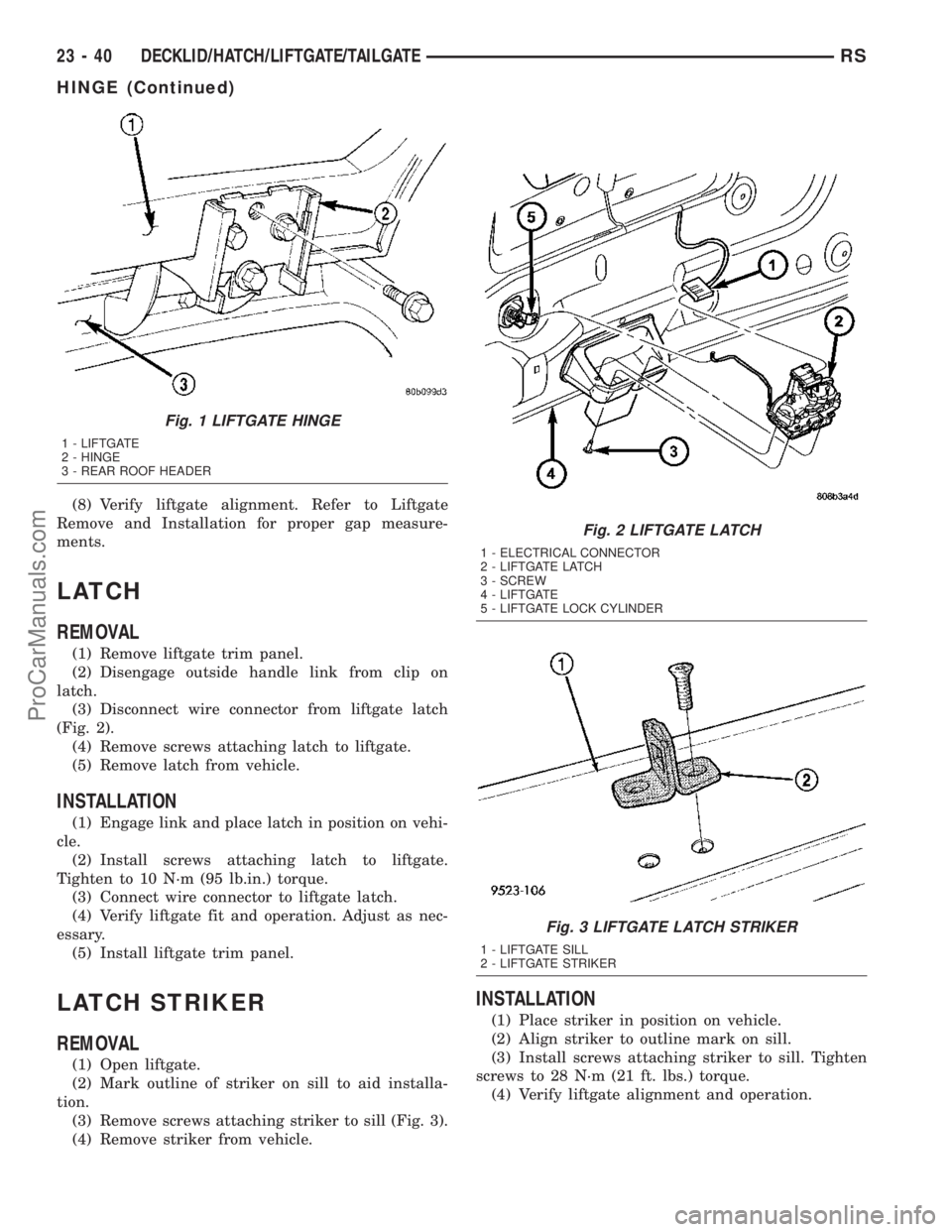
(6) Remove bolts attaching hinge to liftgate (Fig.
1).
(7) Remove hinge from vehicle.
INSTALLATION
(1) If necessary, paint replacement hinge before
installation.
(2) Place hinge in position on vehicle.
(3) Align hinge to marks on liftgate.
(4) Install bolts attaching hinge to liftgate (Fig. 1).
Tighten bolts to 33 N´m (24 ft. lbs.) torque.
(5) Align hinge to marks on roof header.
(6) Install bolts attaching liftgate hinge to roof
header. Tighten outer two bolts to 33 N´m (24 ft. lbs.)
torque. The sheet medal screw at center 12 N´m (105
in. lbs.)
(7) Remove duct tape from roof and liftgate.
RSDECKLID/HATCH/LIFTGATE/TAILGATE23-39
ProCarManuals.com
Page 1773 of 2177
(8) Verify liftgate alignment. Refer to Liftgate
Remove and Installation for proper gap measure-
ments.
LATCH
REMOVAL
(1) Remove liftgate trim panel.
(2) Disengage outside handle link from clip on
latch.
(3) Disconnect wire connector from liftgate latch
(Fig. 2).
(4) Remove screws attaching latch to liftgate.
(5) Remove latch from vehicle.
INSTALLATION
(1) Engage link and place latch in position on vehi-
cle.
(2) Install screws attaching latch to liftgate.
Tighten to 10 N´m (95 lb.in.) torque.
(3) Connect wire connector to liftgate latch.
(4) Verify liftgate fit and operation. Adjust as nec-
essary.
(5) Install liftgate trim panel.
LATCH STRIKER
REMOVAL
(1) Open liftgate.
(2) Mark outline of striker on sill to aid installa-
tion.
(3) Remove screws attaching striker to sill (Fig. 3).
(4) Remove striker from vehicle.
INSTALLATION
(1) Place striker in position on vehicle.
(2) Align striker to outline mark on sill.
(3) Install screws attaching striker to sill. Tighten
screws to 28 N´m (21 ft. lbs.) torque.
(4) Verify liftgate alignment and operation.
Fig. 1 LIFTGATE HINGE
1 - LIFTGATE
2 - HINGE
3 - REAR ROOF HEADER
Fig. 2 LIFTGATE LATCH
1 - ELECTRICAL CONNECTOR
2 - LIFTGATE LATCH
3 - SCREW
4 - LIFTGATE
5 - LIFTGATE LOCK CYLINDER
Fig. 3 LIFTGATE LATCH STRIKER
1 - LIFTGATE SILL
2 - LIFTGATE STRIKER
23 - 40 DECKLID/HATCH/LIFTGATE/TAILGATERS
HINGE (Continued)
ProCarManuals.com
Page 1774 of 2177
LIFTGATE
REMOVAL
(1) Release liftgate latch and open liftgate.
(2) Remove screws attaching liftgate wire connec-
tor to rear header.
(3) Disconnect liftgate wire harness from body
wire harness.
(4) Remove liftgate upper frame molding.
(5) Disconnect rear window washer hose from
spray nozzle.
(6) Support liftgate on a suitable lifting device.
(7) Remove screws attaching support cylinders to
liftgate.
(8) Remove bolts attaching liftgate hinge to roof
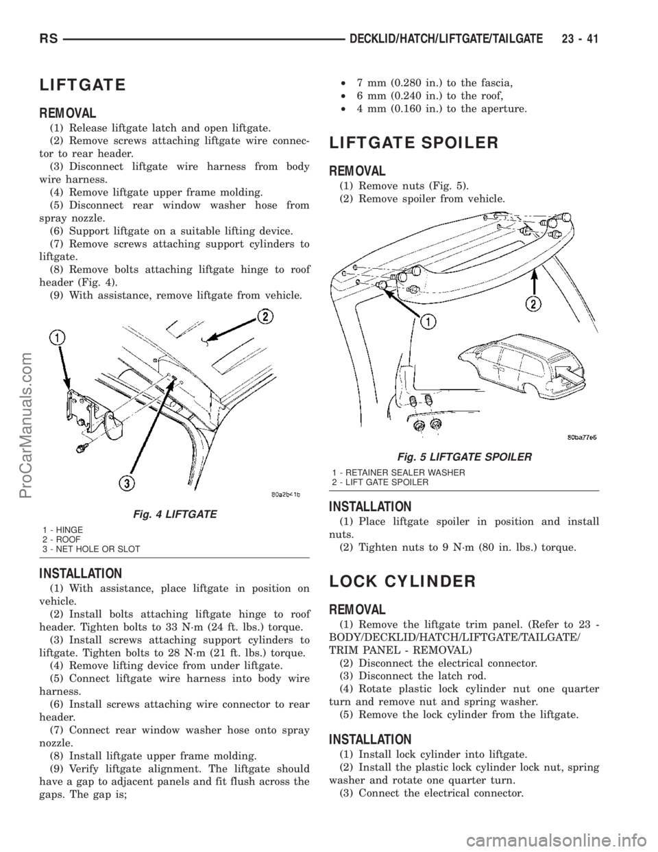
header (Fig. 4).
(9) With assistance, remove liftgate from vehicle.
INSTALLATION
(1) With assistance, place liftgate in position on
vehicle.
(2) Install bolts attaching liftgate hinge to roof
header. Tighten bolts to 33 N´m (24 ft. lbs.) torque.
(3) Install screws attaching support cylinders to
liftgate. Tighten bolts to 28 N´m (21 ft. lbs.) torque.
(4) Remove lifting device from under liftgate.
(5) Connect liftgate wire harness into body wire
harness.
(6) Install screws attaching wire connector to rear
header.
(7) Connect rear window washer hose onto spray
nozzle.
(8) Install liftgate upper frame molding.
(9) Verify liftgate alignment. The liftgate should
have a gap to adjacent panels and fit flush across the
gaps. The gap is;²7 mm (0.280 in.) to the fascia,
²6 mm (0.240 in.) to the roof,
²4 mm (0.160 in.) to the aperture.
LIFTGATE SPOILER
REMOVAL
(1) Remove nuts (Fig. 5).
(2) Remove spoiler from vehicle.
INSTALLATION
(1) Place liftgate spoiler in position and install
nuts.
(2) Tighten nuts to 9 N´m (80 in. lbs.) torque.
LOCK CYLINDER
REMOVAL
(1) Remove the liftgate trim panel. (Refer to 23 -
BODY/DECKLID/HATCH/LIFTGATE/TAILGATE/
TRIM PANEL - REMOVAL)
(2) Disconnect the electrical connector.
(3) Disconnect the latch rod.
(4) Rotate plastic lock cylinder nut one quarter
turn and remove nut and spring washer.
(5) Remove the lock cylinder from the liftgate.
INSTALLATION
(1) Install lock cylinder into liftgate.
(2) Install the plastic lock cylinder lock nut, spring
washer and rotate one quarter turn.
(3) Connect the electrical connector.
Fig. 4 LIFTGATE
1 - HINGE
2 - ROOF
3 - NET HOLE OR SLOT
Fig. 5 LIFTGATE SPOILER
1 - RETAINER SEALER WASHER
2 - LIFT GATE SPOILER
RSDECKLID/HATCH/LIFTGATE/TAILGATE23-41
ProCarManuals.com
Page 1775 of 2177

(4) Connect the latch rod.
(5) Install the trim panel. (Refer to 23 - BODY/
DECKLID/HATCH/LIFTGATE/TAILGATE/TRIM
PANEL - INSTALLATION)
(6) Verify lock cylinder operation.
SUPPORT CYLINDER
REMOVAL
(1) Release liftgate latch and open liftgate.
(2) Support liftgate on a suitable lifting device in
the full open position.
(3) Pull liftgate opening weatherstrip from D-pillar
flange next to prop assembly end pivot.
(4) Remove bolt attaching end pivot to D-pillar
(Fig. 6).
(5) Remove bolt attaching prop assembly to lift-
gate.
(6) Remove prop assembly from vehicle.
INSTALLATION
Ensure that the cylinder end is attached to the
D-pillar and the shaft end is attached to the liftgate.
(1) Place prop assembly in position.
(2) Install bolt attaching prop assembly to liftgate.
(3) Install bolt attaching end pivot to D-pillar.
Tighten bolts to 28 N´m (21 ft. lbs.) torque.
(4) Install liftgate opening weatherstrip to D-pillar
flange next to prop assembly end pivot.
(5) Close liftgate. Check liftgate operation.
TRIM PANEL
REMOVAL
(1) Remove the bolt attaching the lift motor link, if
equipped (Fig. 7).
(2) Remove liftgate upper frame molding (Fig. 8).
(3) Remove assist handle screws.
(4) Disengage hidden clips holding trim panel to
liftgate from around perimeter or liftgate (Fig. 8).
(5) Disconnect wire connector from lamps.
(6) Remove liftgate trim panel from vehicle.
Fig. 6 LIFTGATE PROP ASSEMBLY
1 - LIFTGATE
2 - PROP ASSEMBLY
Fig. 7 LIFTGATE MOTOR
1 - LIFTGATE MOTOR LINK BOLT
2 - LIFTGATE MOTOR
3 - LIFTGATE
Fig. 8 LIFTGATE TRIM
1 - LIFTGATE
2 - LOWER TRIM PANEL
3 - ASSIST HANDLE SCREWS
4 - UPPER TRIM
5 - UPPER TRIM CLIPS
23 - 42 DECKLID/HATCH/LIFTGATE/TAILGATERS
LOCK CYLINDER (Continued)
ProCarManuals.com