2003 CHRYSLER CARAVAN lock
[x] Cancel search: lockPage 1269 of 2177
(8) Install the generator and wiring harness (Refer
to 8 - ELECTRICAL/CHARGING/GENERATOR -
INSTALLATION).
(9) Raise vehicle.
(10) Attach wiring harness support clip to the
engine oil dipstick tube.
(11) Connect oil pressure switch electrical connec-
tor.
(12) Install the A/C compressor.
(13) Install the water pump pulley.
(14) Connect the radiator lower hose.(15) Install the accessory drive belt and splash
shield (Refer to 7 - COOLING/ACCESSORY DRIVE/
DRIVE BELTS - INSTALLATION).
(16) Connect the engine block heater electrical con-
nector (if equipped).
(17) Connect the knock sensor electrical connector
(3.8L only).
(18) Install the torque converter to flex plate bolts.
(19) Install the transaxle case cover (Fig. 8).
(20) Install the powertrain struts (Fig. 8).
(21) Install the engine rear mount bracket.
(22) Install the engine front mount and bracket
assembly.
(23)AWD equipped;Install the power transfer
unit (PTU) (Refer to 21 - TRANSMISSION/TRANS-
AXLE/POWER TRANSFER UNIT - INSTALLA-
TION).
(24) Install the axle shafts (Refer to 3 - DIFFER-
ENTIAL & DRIVELINE/HALF SHAFT - INSTALLA-
TION).
(25) Connect exhaust pipe to manifold (Fig. 7).
(26) Install crossmember cradle plate (Fig. 6).
(27) Lower vehicle.
(28) Connect transaxle shift linkage.
(29) Connect transaxle electrical connectors.
(30) Remove plugs from transmission cooler hoses
and install transaxle oil cooler line service splice kit.
Refer to instructions included with kit.
(31) Install transaxle dipstick tube and attach
electrical harness clip.
(32) Connect the A/C lines to compressor.
(33) Connect the A/C compressor electrical connec-
tor.
(34) Evacuate and recharge A/C system.
(35) Connect crankshaft and camshaft position
sensors.
(36) Connect the fuel injector electrical harness
connector and engage clip to support bracket.
(37) Connect engine coolant temperature (ECT)
sensor and ignition coil electrical connectors.
(38) Connect the ground strap to rear of cylinder
head.
(39) Install power steering reservoir.
(40) Engage wire harness clip to engine right side
mount.
(41) Connect the brake booster and speed control
vacuum hoses.
(42) Connect the vacuum hoses to the throttle
body.
(43) Connect the EGR transducer electrical connec-
tor (if equipped).
(44) Connect the TPS, IAC, and MAP sensor elec-
trical connectors.
(45) Connect throttle cables to throttle body.
(46) Install the radiator fans (Refer to 7 - COOL-
ING/ENGINE/RADIATOR FAN - INSTALLATION).
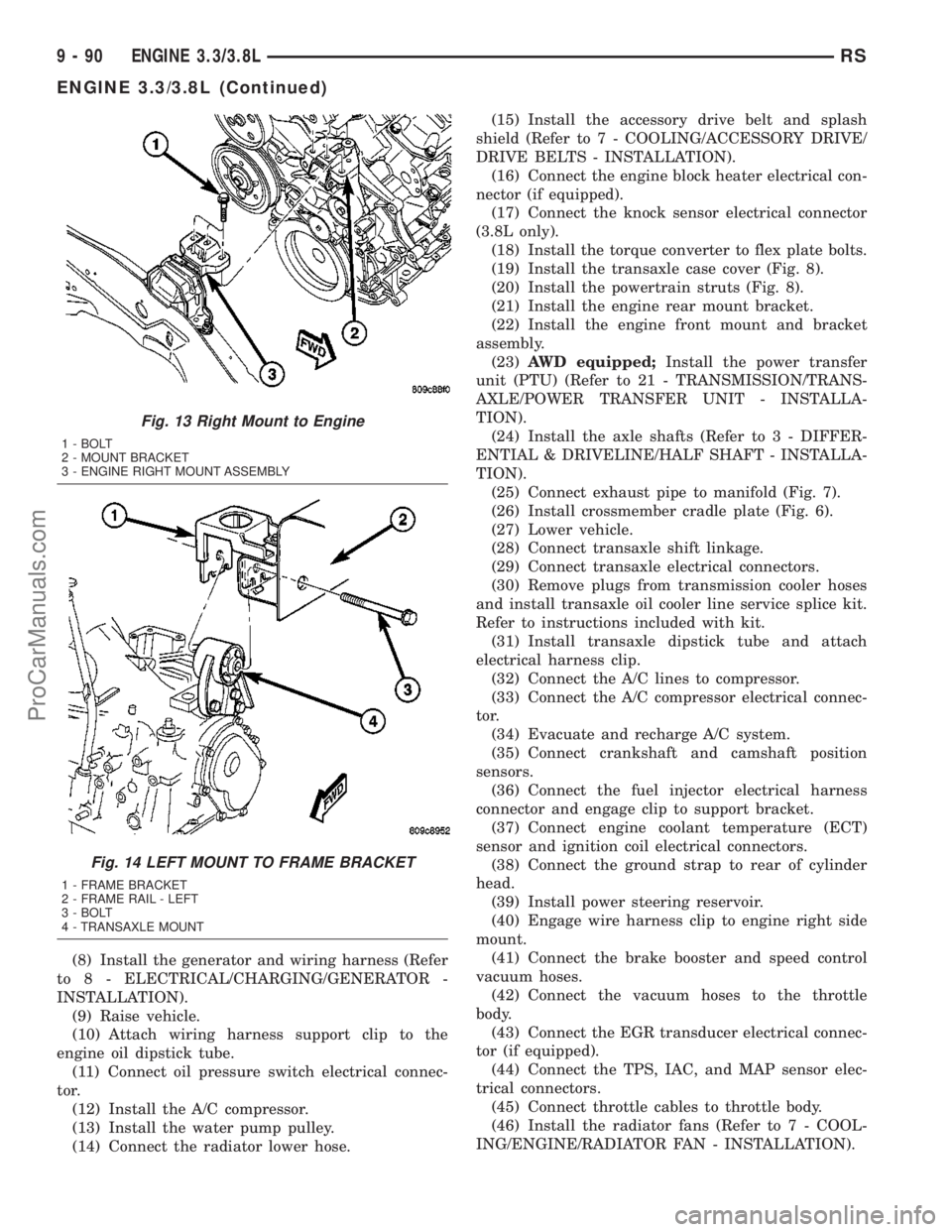
Fig. 13 Right Mount to Engine
1 - BOLT
2 - MOUNT BRACKET
3 - ENGINE RIGHT MOUNT ASSEMBLY
Fig. 14 LEFT MOUNT TO FRAME BRACKET
1 - FRAME BRACKET
2 - FRAME RAIL - LEFT
3 - BOLT
4 - TRANSAXLE MOUNT
9 - 90 ENGINE 3.3/3.8LRS
ENGINE 3.3/3.8L (Continued)
ProCarManuals.com
Page 1270 of 2177
(47) Connect the radiator upper hose.
(48) Connect the heater hoses. Remove pinch-off
pliers from the rear heater hoses (if equipped).
(49) Install the radiator upper support crossmem-
ber (Refer to 23 - BODY/EXTERIOR/GRILLE OPEN-
ING REINFORCEMENT - INSTALLATION).
(50) Install the wiper module (Refer to 8 - ELEC-
TRICAL/WIPERS/WASHERS/WIPER MODULE -
INSTALLATION).
(51) Connect the fuel line to fuel rail (Refer to 14 -
FUEL SYSTEM/FUEL DELIVERY/FUEL LINES -
STANDARD PROCEDURE).
(52) Install the air cleaner and hoses.
(53) Install new oil filter. Fill engine crankcase
with proper oil to correct level.
(54) Connect negative cable to battery.
(55) Fill the cooling system (Refer to 7 - COOLING
- STANDARD PROCEDURE).
(56) Start engine and run until operating temper-
ature is reached.
(57) Adjust transmission linkage, if necessary.
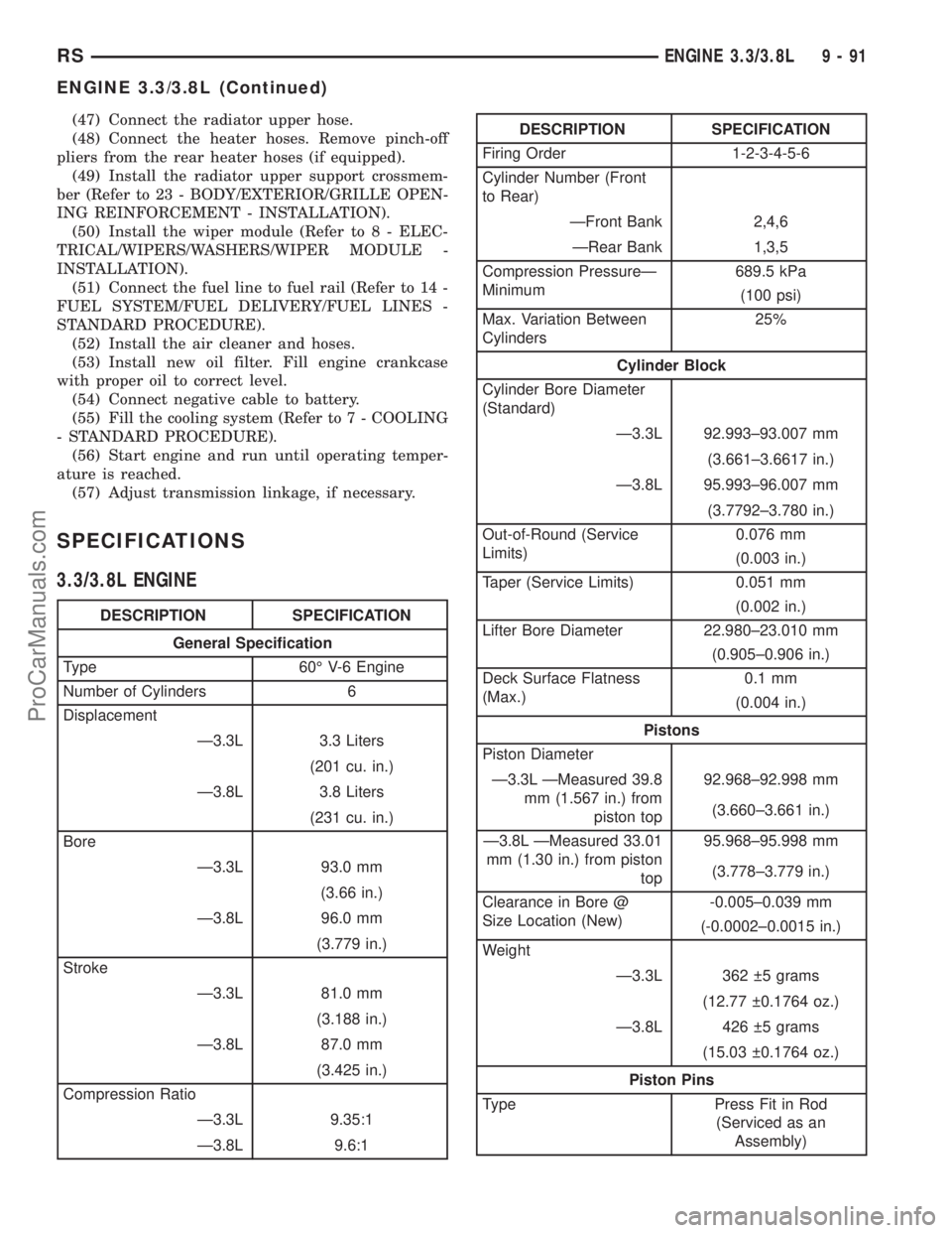
SPECIFICATIONS
3.3/3.8L ENGINE
DESCRIPTION SPECIFICATION
General Specification
Type 60É V-6 Engine
Number of Cylinders 6
Displacement
Ð3.3L 3.3 Liters
(201 cu. in.)
Ð3.8L 3.8 Liters
(231 cu. in.)
Bore
Ð3.3L 93.0 mm
(3.66 in.)
Ð3.8L 96.0 mm
(3.779 in.)
Stroke
Ð3.3L 81.0 mm
(3.188 in.)
Ð3.8L 87.0 mm
(3.425 in.)
Compression Ratio
Ð3.3L 9.35:1
Ð3.8L 9.6:1
DESCRIPTION SPECIFICATION
Firing Order 1-2-3-4-5-6
Cylinder Number (Front
to Rear)
ÐFront Bank 2,4,6
ÐRear Bank 1,3,5
Compression PressureÐ
Minimum689.5 kPa
(100 psi)
Max. Variation Between
Cylinders25%
Cylinder Block
Cylinder Bore Diameter
(Standard)
Ð3.3L 92.993±93.007 mm
(3.661±3.6617 in.)
Ð3.8L 95.993±96.007 mm
(3.7792±3.780 in.)
Out-of-Round (Service
Limits)0.076 mm
(0.003 in.)
Taper (Service Limits) 0.051 mm
(0.002 in.)
Lifter Bore Diameter 22.980±23.010 mm
(0.905±0.906 in.)
Deck Surface Flatness
(Max.)0.1 mm
(0.004 in.)
Pistons
Piston Diameter
Ð3.3L ÐMeasured 39.8
mm (1.567 in.) from
piston top92.968±92.998 mm
(3.660±3.661 in.)
Ð3.8L ÐMeasured 33.01
mm (1.30 in.) from piston
top95.968±95.998 mm
(3.778±3.779 in.)
Clearance in Bore @
Size Location (New)-0.005±0.039 mm
(-0.0002±0.0015 in.)
Weight
Ð3.3L 362 5 grams
(12.77 0.1764 oz.)
Ð3.8L 426 5 grams
(15.03 0.1764 oz.)
Piston Pins
Type Press Fit in Rod
(Serviced as an
Assembly)
RSENGINE 3.3/3.8L9-91
ENGINE 3.3/3.8L (Continued)
ProCarManuals.com
Page 1272 of 2177
DESCRIPTION SPECIFICATION
Main Bearing Diametrical
Clearance
ÐNo. 1, 2, 3, 4 0.011±0.055 mm
(0.0005±0.0022 in.)
Wear Limit 0.076 mm
(0.003 in.)
Camshaft
Journal Diameter
No.1 50.724±50.775 mm
(1.997±1.999 in.)
No.2 50.317±50.368 mm
(1.9809±1.9829 in.)
No.3 49.936±49.987 mm
(1.9659±1.9679 in.)
No.4 49.530±49.581 mm
(1.9499±1.9520 in.)
Bearing ClearanceÐ
Diametrical0.025±0.101 mm
(0.001±0.004 in.)
Bearing Clearance (Max.
allowable)0.127 mm
(0.005 in.)
End Play 0.254±0.508 mm
(0.010±0.020 in.)
(Max. allowable) 0.304 mm
(0.012 in.)
Camshaft Bearing
Diameter
No. 1 50.800±50.825 mm
(1.9999±2.0009 in.)
No. 2 50.393±50.419 mm
(1.9839±1.9849 in.)
No. 3 50.013±50.038 mm
(1.9690±1.9699 in.)
No. 4 49.606±49.632 mm
(1.9529±1.954 in.)
Exhaust Valve Timing
ClosesÐ3.3L (ATDC) 13É
ClosesÐ3.8L (ATDC) 18É
OpensÐ3.3L (BBDC) 43É
OpensÐ3.8L (BBDC) 46É
DurationÐ3.3L 236É
DurationÐ3.8L 244ÉDESCRIPTION SPECIFICATION
Intake Valve Timing
ClosesÐ3.3L (ABDC 52É
ClosesÐ3.8L (ABDC 63É
OpensÐ3.3L (ATDC) 6É
OpensÐ3.8L (ATDC) 1É
DurationÐ3.3L 226É
DurationÐ3.8L 242É
Valve OverlapÐ3.3L 7É
Valve OverlapÐ3.8L 17É
Lifters
Type Hydraulic Roller
Diameter O.D. 22.949±22.962 mm
(0.903±0.904 in.)
Clearance In Block 0.020±0.061 mm
0.0007±0.0024 in.)
Cylinder Head
Gasket Thickness
(Compressed)0.65±0.75 mm
(0.025±0.029 in.)
Valve Seat
Angle 44.5±45É
Valve Seat Runout
(Service Limits)0.0762 mm
(0.003 in.)
Valve Seat WidthÐIntake
& Exhaust1.50±2.00 mm
(0.057±0.078 in.)
Valve Guide
Guide Bore Diameter
(Std.)6.975±7.00 mm
(0.274±0.275 in.)
Valves
Valve Lift (Zero
Lash)ÐIntake & Exhaust
Ð3.3L 9.80 mm
(0.385 in.)
Ð3.8L 11.0 mm
(0.433 in.)
Face AngleÐIntake 45±45.5É
Face AngleÐExhaust 45±45.5É
Head DiameterÐIntake 47.87±48.13 mm
(1.88±1.89 in.)
Head DiameterÐExhaust 35.37±35.63 mm
(1.39±1.40 in.)
RSENGINE 3.3/3.8L9-93
ENGINE 3.3/3.8L (Continued)
ProCarManuals.com
Page 1274 of 2177
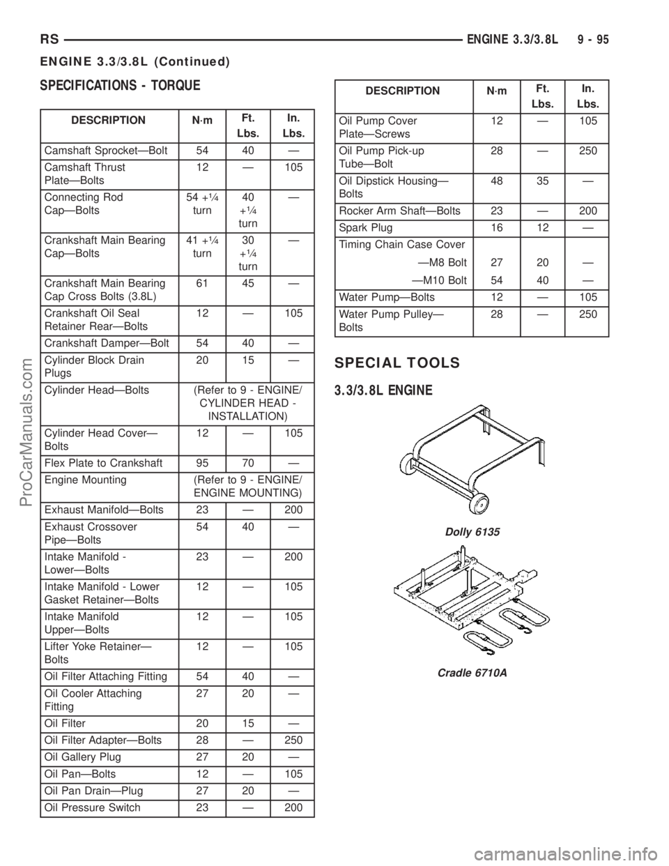
SPECIFICATIONS - TORQUE
DESCRIPTION N´mFt.
Lbs.In.
Lbs.
Camshaft SprocketÐBolt 54 40 Ð
Camshaft Thrust
PlateÐBolts12 Ð 105
Connecting Rod
CapÐBolts54 +
1¤4
turn40
+1¤4
turnÐ
Crankshaft Main Bearing
CapÐBolts41 +
1¤4
turn30
+1¤4
turnÐ
Crankshaft Main Bearing
Cap Cross Bolts (3.8L)61 45 Ð
Crankshaft Oil Seal
Retainer RearÐBolts12 Ð 105
Crankshaft DamperÐBolt 54 40 Ð
Cylinder Block Drain
Plugs20 15 Ð
Cylinder HeadÐBolts (Refer to 9 - ENGINE/
CYLINDER HEAD -
INSTALLATION)
Cylinder Head CoverÐ
Bolts12 Ð 105
Flex Plate to Crankshaft 95 70 Ð
Engine Mounting (Refer to 9 - ENGINE/
ENGINE MOUNTING)
Exhaust ManifoldÐBolts 23 Ð 200
Exhaust Crossover
PipeÐBolts54 40 Ð
Intake Manifold -
LowerÐBolts23 Ð 200
Intake Manifold - Lower
Gasket RetainerÐBolts12 Ð 105
Intake Manifold
UpperÐBolts12 Ð 105
Lifter Yoke RetainerÐ
Bolts12 Ð 105
Oil Filter Attaching Fitting 54 40 Ð
Oil Cooler Attaching
Fitting27 20 Ð
Oil Filter 20 15 Ð
Oil Filter AdapterÐBolts 28 Ð 250
Oil Gallery Plug 27 20 Ð
Oil PanÐBolts 12 Ð 105
Oil Pan DrainÐPlug 27 20 Ð
Oil Pressure Switch 23 Ð 200
DESCRIPTION N´mFt.
Lbs.In.
Lbs.
Oil Pump Cover
PlateÐScrews12 Ð 105
Oil Pump Pick-up
TubeÐBolt28 Ð 250
Oil Dipstick HousingÐ
Bolts48 35 Ð
Rocker Arm ShaftÐBolts 23 Ð 200
Spark Plug 16 12 Ð
Timing Chain Case Cover
ÐM8 Bolt 27 20 Ð
ÐM10 Bolt 54 40 Ð
Water PumpÐBolts 12 Ð 105
Water Pump PulleyÐ
Bolts28 Ð 250
SPECIAL TOOLS
3.3/3.8L ENGINE
Dolly 6135
Cradle 6710A
RSENGINE 3.3/3.8L9-95
ENGINE 3.3/3.8L (Continued)
ProCarManuals.com
Page 1278 of 2177
AIR CLEANER HOUSING
REMOVAL
(1) Disconnect the negative battery cable.
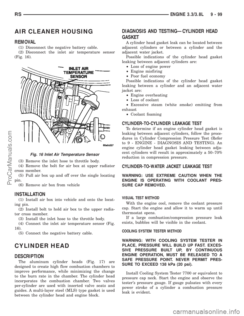
(2) Disconnect the inlet air temperature sensor
(Fig. 16).
(3) Remove the inlet hose to throttle body.
(4) Remove the bolt for air box at upper radiator
cross member.
(5) Pull air box up and off over the single locating
pin.
(6) Remove air box from vehicle
INSTALLATION
(1) Install air box into vehicle and onto the locat-
ing pin.
(2) Install bolt to hold air box to the upper radia-
tor cross member.
(3) Install the inlet hose to the throttle body.
(4) Connect the inlet air temperature sensor (Fig.
16).
(5) Connect the negative battery cable.
CYLINDER HEAD
DESCRIPTION
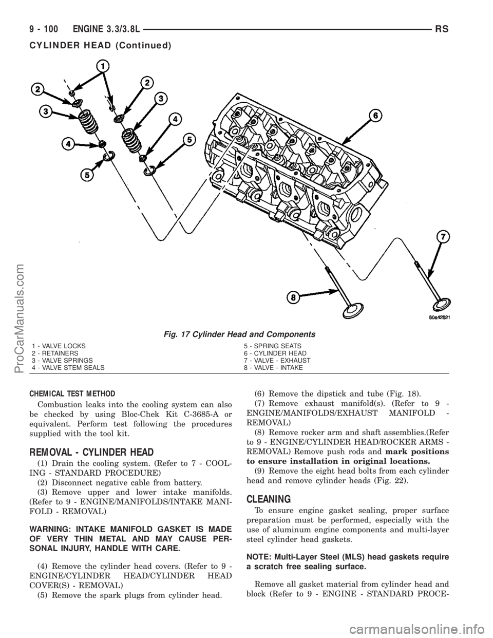
The aluminum cylinder heads (Fig. 17) are
designed to create high flow combustion chambers to
improve performance, while minimizing the change
to the burn rate in the chamber. The cylinder head
incorporates the combustion chamber. Two valves
per-cylinder are used with inserted valve seats and
guides. A multi-layer steel (MLS) type gasket is used
between the cylinder head and engine block.
DIAGNOSIS AND TESTINGÐCYLINDER HEAD
GASKET
A cylinder head gasket leak can be located between
adjacent cylinders or between a cylinder and the
adjacent water jacket.
Possible indications of the cylinder head gasket
leaking between adjacent cylinders are:
²Loss of engine power
²Engine misfiring
²Poor fuel economy
Possible indications of the cylinder head gasket
leaking between a cylinder and an adjacent water
jacket are:
²Engine overheating
²Loss of coolant
²Excessive steam (white smoke) emitting from
exhaust
²Coolant foaming
CYLINDER-TO-CYLINDER LEAKAGE TEST
To determine if an engine cylinder head gasket is
leaking between adjacent cylinders, follow the proce-
dures in Cylinder Compression Pressure Test (Refer
to 9 - ENGINE - DIAGNOSIS AND TESTING). An
engine cylinder head gasket leaking between adja-
cent cylinders will result in approximately a 50±70%
reduction in compression pressure.
CYLINDER-TO-WATER JACKET LEAKAGE TEST
WARNING: USE EXTREME CAUTION WHEN THE
ENGINE IS OPERATING WITH COOLANT PRES-
SURE CAP REMOVED.
VISUAL TEST METHOD
With the engine cool, remove the coolant pressure
cap. Start the engine and allow it to warm up until
thermostat opens.
If a large combustion/compression pressure leak
exists, bubbles will be visible in the coolant.
COOLING SYSTEM TESTER METHOD
WARNING: WITH COOLING SYSTEM TESTER IN
PLACE, PRESSURE WILL BUILD UP FAST. EXCES-
SIVE PRESSURE BUILT UP, BY CONTINUOUS
ENGINE OPERATION, MUST BE RELEASED TO A
SAFE PRESSURE POINT. NEVER PERMIT PRES-
SURE TO EXCEED 138 kPa (20 psi).
Install Cooling System Tester 7700 or equivalent to
pressure cap neck. Start the engine and observe the
tester's pressure gauge. If gauge pulsates with every
power stroke of a cylinder a combustion pressure
leak is evident.
Fig. 16 Inlet Air Temperature Sensor
RSENGINE 3.3/3.8L9-99
ProCarManuals.com
Page 1279 of 2177
CHEMICAL TEST METHOD
Combustion leaks into the cooling system can also
be checked by using Bloc-Chek Kit C-3685-A or
equivalent. Perform test following the procedures
supplied with the tool kit.
REMOVAL - CYLINDER HEAD
(1) Drain the cooling system. (Refer to 7 - COOL-
ING - STANDARD PROCEDURE)
(2) Disconnect negative cable from battery.
(3) Remove upper and lower intake manifolds.
(Refer to 9 - ENGINE/MANIFOLDS/INTAKE MANI-
FOLD - REMOVAL)
WARNING: INTAKE MANIFOLD GASKET IS MADE
OF VERY THIN METAL AND MAY CAUSE PER-
SONAL INJURY, HANDLE WITH CARE.
(4) Remove the cylinder head covers. (Refer to 9 -
ENGINE/CYLINDER HEAD/CYLINDER HEAD
COVER(S) - REMOVAL)
(5) Remove the spark plugs from cylinder head.(6) Remove the dipstick and tube (Fig. 18).
(7) Remove exhaust manifold(s). (Refer to 9 -
ENGINE/MANIFOLDS/EXHAUST MANIFOLD -
REMOVAL)
(8) Remove rocker arm and shaft assemblies.(Refer
to 9 - ENGINE/CYLINDER HEAD/ROCKER ARMS -
REMOVAL) Remove push rods andmark positions
to ensure installation in original locations.
(9) Remove the eight head bolts from each cylinder
head and remove cylinder heads (Fig. 22).
CLEANING
To ensure engine gasket sealing, proper surface
preparation must be performed, especially with the
use of aluminum engine components and multi-layer
steel cylinder head gaskets.
NOTE: Multi-Layer Steel (MLS) head gaskets require
a scratch free sealing surface.
Remove all gasket material from cylinder head and
block (Refer to 9 - ENGINE - STANDARD PROCE-
Fig. 17 Cylinder Head and Components
1 - VALVE LOCKS 5 - SPRING SEATS
2 - RETAINERS 6 - CYLINDER HEAD
3 - VALVE SPRINGS 7 - VALVE - EXHAUST
4 - VALVE STEM SEALS 8 - VALVE - INTAKE
9 - 100 ENGINE 3.3/3.8LRS
CYLINDER HEAD (Continued)
ProCarManuals.com
Page 1280 of 2177
DURE). Be careful not to gouge or scratch the alumi-
num head sealing surface.
Clean all engine oil passages.
INSPECTION
(1) Before cleaning, check for leaks, damage and
cracks.
(2) Clean cylinder head and oil passages.
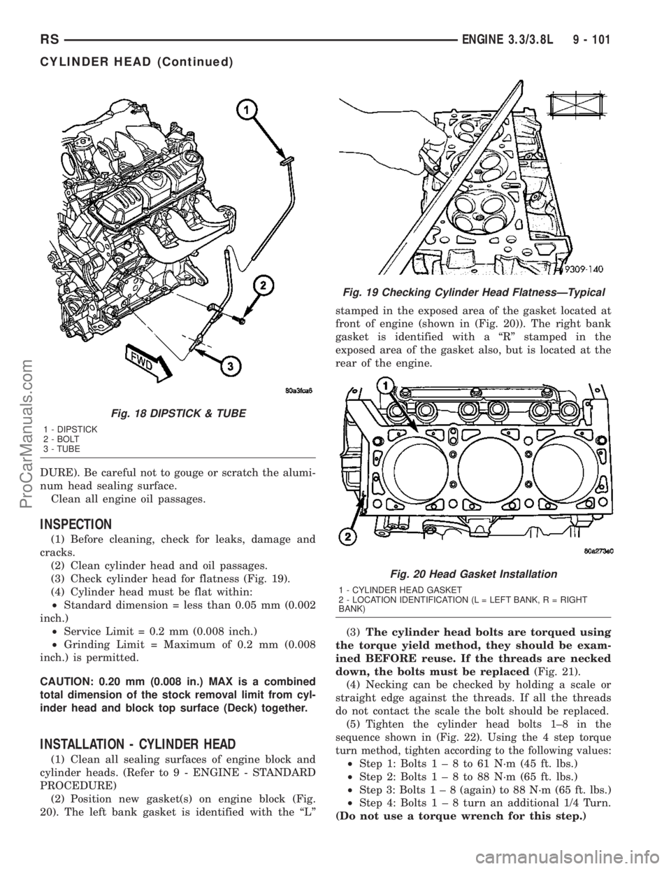
(3) Check cylinder head for flatness (Fig. 19).
(4) Cylinder head must be flat within:
²Standard dimension = less than 0.05 mm (0.002
inch.)
²Service Limit = 0.2 mm (0.008 inch.)
²Grinding Limit = Maximum of 0.2 mm (0.008
inch.) is permitted.
CAUTION: 0.20 mm (0.008 in.) MAX is a combined
total dimension of the stock removal limit from cyl-
inder head and block top surface (Deck) together.
INSTALLATION - CYLINDER HEAD
(1) Clean all sealing surfaces of engine block and
cylinder heads. (Refer to 9 - ENGINE - STANDARD
PROCEDURE)
(2) Position new gasket(s) on engine block (Fig.
20). The left bank gasket is identified with the ªLºstamped in the exposed area of the gasket located at
front of engine (shown in (Fig. 20)). The right bank
gasket is identified with a ªRº stamped in the
exposed area of the gasket also, but is located at the
rear of the engine.
(3)The cylinder head bolts are torqued using
the torque yield method, they should be exam-
ined BEFORE reuse. If the threads are necked
down, the bolts must be replaced(Fig. 21).
(4) Necking can be checked by holding a scale or
straight edge against the threads. If all the threads
do not contact the scale the bolt should be replaced.
(5)
Tighten the cylinder head bolts 1±8 in the
sequence shown in (Fig. 22). Using the 4 step torque
turn method, tighten according to the following values:
²Step 1: Bolts1±8to61N´m(45ft.lbs.)
²Step 2: Bolts1±8to88N´m(65ft.lbs.)
²Step 3: Bolts1±8(again) to 88 N´m (65 ft. lbs.)
²Step 4: Bolts1±8turn an additional 1/4 Turn.
(Do not use a torque wrench for this step.)
Fig. 18 DIPSTICK & TUBE
1 - DIPSTICK
2 - BOLT
3 - TUBE
Fig. 19 Checking Cylinder Head FlatnessÐTypical
Fig. 20 Head Gasket Installation
1 - CYLINDER HEAD GASKET
2 - LOCATION IDENTIFICATION (L = LEFT BANK, R = RIGHT
BANK)
RSENGINE 3.3/3.8L9 - 101
CYLINDER HEAD (Continued)
ProCarManuals.com
Page 1283 of 2177
(2) Assemble gasket to cylinder cover by inserting
the fasteners through each bolt hole on cover and
gasket (Fig. 25).
(3) Install the cylinder head cover and bolts (Fig.
26).
(4) Tighten cylinder head cover bolts to 12 N´m
(105 in. lbs.) (Fig. 26).
(5) Connect crankcase vent hose.
(6) Connect spark plug wires to spark plugs.
INTAKE/EXHAUST VALVES &
SEATS
DESCRIPTION
The valves have chrome plated valve stems with
four-bead lock grooves. The valve stem seals are
made of Viton rubber.
OPERATION
The two valves per cylinder are opened using
hydraulic lifters, push rods, and rocker arms.
STANDARD PROCEDURE - REFACING VALVES
AND VALVE SEATS
The intake and exhaust valves and seats are
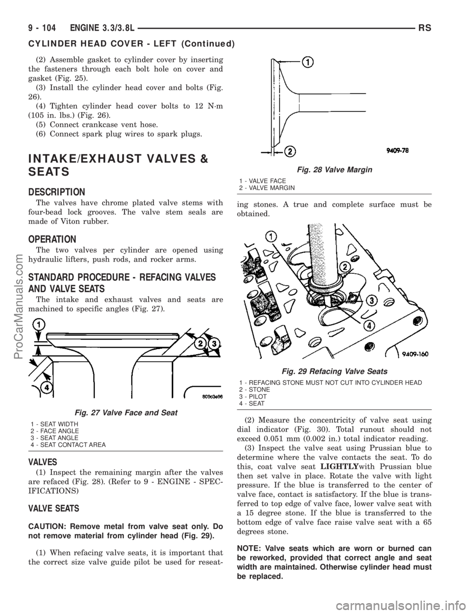
machined to specific angles (Fig. 27).
VALVES
(1) Inspect the remaining margin after the valves
are refaced (Fig. 28). (Refer to 9 - ENGINE - SPEC-
IFICATIONS)
VALVE SEATS
CAUTION: Remove metal from valve seat only. Do
not remove material from cylinder head (Fig. 29).
(1) When refacing valve seats, it is important that
the correct size valve guide pilot be used for reseat-ing stones. A true and complete surface must be
obtained.
(2) Measure the concentricity of valve seat using
dial indicator (Fig. 30). Total runout should not
exceed 0.051 mm (0.002 in.) total indicator reading.
(3) Inspect the valve seat using Prussian blue to
determine where the valve contacts the seat. To do
this, coat valve seatLIGHTLYwith Prussian blue
then set valve in place. Rotate the valve with light
pressure. If the blue is transferred to the center of
valve face, contact is satisfactory. If the blue is trans-
ferred to top edge of valve face, lower valve seat with
a 15 degree stone. If the blue is transferred to the
bottom edge of valve face raise valve seat with a 65
degrees stone.
NOTE: Valve seats which are worn or burned can
be reworked, provided that correct angle and seat
width are maintained. Otherwise cylinder head must
be replaced.
Fig. 27 Valve Face and Seat
1 - SEAT WIDTH
2 - FACE ANGLE
3 - SEAT ANGLE
4 - SEAT CONTACT AREA
Fig. 28 Valve Margin
1 - VALVE FACE
2 - VALVE MARGIN
Fig. 29 Refacing Valve Seats
1 - REFACING STONE MUST NOT CUT INTO CYLINDER HEAD
2-STONE
3 - PILOT
4 - SEAT
9 - 104 ENGINE 3.3/3.8LRS
CYLINDER HEAD COVER - LEFT (Continued)
ProCarManuals.com