2003 CHRYSLER CARAVAN wiper fluid
[x] Cancel search: wiper fluidPage 1059 of 2177
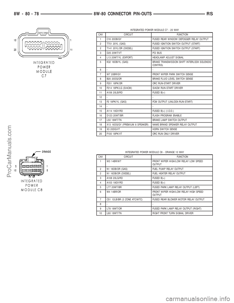
INTEGRATED POWER MODULE C7 - 20 WAY
CAV CIRCUIT FUNCTION
1 C16 20DB/GY FUSED REAR WINDOW DEFOGGER RELAY OUTPUT
2 T751 20YL (GAS) FUSED IGNITION SWITCH OUTPUT (START)
2 T141 20YL/OR (DIESEL) FUSED IGNITION SWITCH OUTPUT (START)
3 D25 20WT/VT PCI BUS
4 L13 20WT/YL (EXPORT) HEADLAMP ADJUST SIGNAL
5 K32 18DB/YL (GAS) BRAKE TRANSMISSION SHIFT INTERLOCK SOLENOID
CONTROL
6- -
7 W7 20BR/GY FRONT WIPER PARK SWITCH SENSE
8 B20 20DG/OR BRAKE FLUID LEVEL SWITCH SENSE
9 F201 18PK/OR ORC RUN-START DRIVER
10 F214 18PK/LG (SIACM) SIACM RUN-START DRIVER
11 A106 20LB/RD FUSED B(+)
12 - -
13 F2 18PK/YL (GAS) FCM OUTPUT (UNLOCK-RUN-START)
14 - -
15 A114 16GY/RD FUSED B(+) (I.O.D.)
16 D123 20WT/BR FLASH PROGRAM ENABLE
17 L50 18WT/TN BRAKE LAMP SWITCH OUTPUT
18 X13 16DG/GY (PREMIUM 8 SPEAKER) NAME BRAND SPEAKER RELAY OUTPUT
19 X3 20DG/VT HORN SWITCH SENSE
20 F100 18PK/VT ORC RUN ONLY DRIVER
INTEGRATED POWER MODULE C8 - ORANGE 10 WAY
CAV CIRCUIT FUNCTION
1 W3 14BR/WT FRONT WIPER HIGH/LOW RELAY LOW SPEED
OUTPUT
2 N1 18DB/OR (GAS) FUEL PUMP RELAY OUTPUT
2 N1 16DB/OR (DIESEL) FUEL HEATER RELAY OUTPUT
3 A108 20LG/RD FUSED B(+)
4 A103 18GY/RD FUSED B(+)
5 L77 20WT/BR FUSED PARK LAMP RELAY OUTPUT (LEFT)
6 W4 14BR/OR FRONT WIPER HIGH/LOW RELAY HIGH SPEED
OUTPUT
7 C51 12LB/BR (3 ZONE ATC/MTC) FUSED REAR BLOWER MOTOR RELAY OUTPUT
8- -
9 L78 18WT/OR FUSED PARK LAMP RELAY OUTPUT (RIGHT)
10 L60 18WT/TN RIGHT FRONT TURN SIGNAL DRIVER
8W - 80 - 78 8W-80 CONNECTOR PIN-OUTSRS
ProCarManuals.com
Page 1115 of 2177
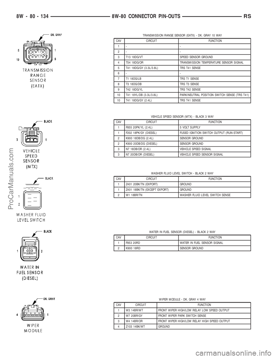
TRANSMISSION RANGE SENSOR (EATX) - DK. GRAY 10 WAY
CAV CIRCUIT FUNCTION
1- -
2- -
3 T13 18DG/VT SPEED SENSOR GROUND
4 T54 18DG/OR TRANSMISSION TEMPERATURE SENSOR SIGNAL
5 T41 18DG/GY (3.3L/3.8L) TRS T41 SENSE
6- -
7 T1 18DG/LB TRS T1 SENSE
8 T3 18DG/DB TRS T3 SENSE
9 T42 18DG/YL TRS T42 SENSE
10 T41 18YL/DB (3.3L/3.8L) PARK/NEUTRAL POSITION SWITCH SENSE (TRS T41)
10 T41 18DG/GY (2.4L) TRS T41 SENSE
VEHICLE SPEED SENSOR (MTX) - BLACK 3 WAY
CAV CIRCUIT FUNCTION
1 F855 20PK/YL (2.4L) 5 VOLT SUPPLY
1 F202 18PK/GY (DIESEL) FUSED IGNITION SWITCH OUTPUT (RUN-START)
2 K900 18DB/DG (2.4L) SENSOR GROUND
2 K900 20DB/DG (DIESEL) SENSOR GROUND
3 N7 18DB/OR (2.4L) VEHICLE SPEED SIGNAL
3 N7 20DB/OR (DIESEL) VEHICLE SPEED SENSOR SIGNAL
WASHER FLUID LEVEL SWITCH - BLACK 2 WAY
CAV CIRCUIT FUNCTION
1 Z401 20BK/TN (EXPORT) GROUND
1 Z401 18BK/TN (EXCEPT EXPORT) GROUND
2 W1 18BR/TN WASHER FLUID LEVEL SWITCH SENSE
WATER IN FUEL SENSOR (DIESEL) - BLACK 2 WAY
CAV CIRCUIT FUNCTION
1 F853 20RD WATER IN FUEL SENSOR SIGNAL
2 K900 18RD SENSOR GROUND
WIPER MODULE - DK. GRAY 4 WAY
CAV CIRCUIT FUNCTION
1 W3 14BR/WT FRONT WIPER HIGH/LOW RELAY LOW SPEED OUTPUT
2 W7 20BR/GY FRONT WIPER PARK SWITCH SENSE
3 W4 14BR/OR FRONT WIPER HIGH/LOW RELAY HIGH SPEED OUTPUT
4 Z103 14BK/WT GROUND
8W - 80 - 134 8W-80 CONNECTOR PIN-OUTSRS
ProCarManuals.com
Page 1126 of 2177
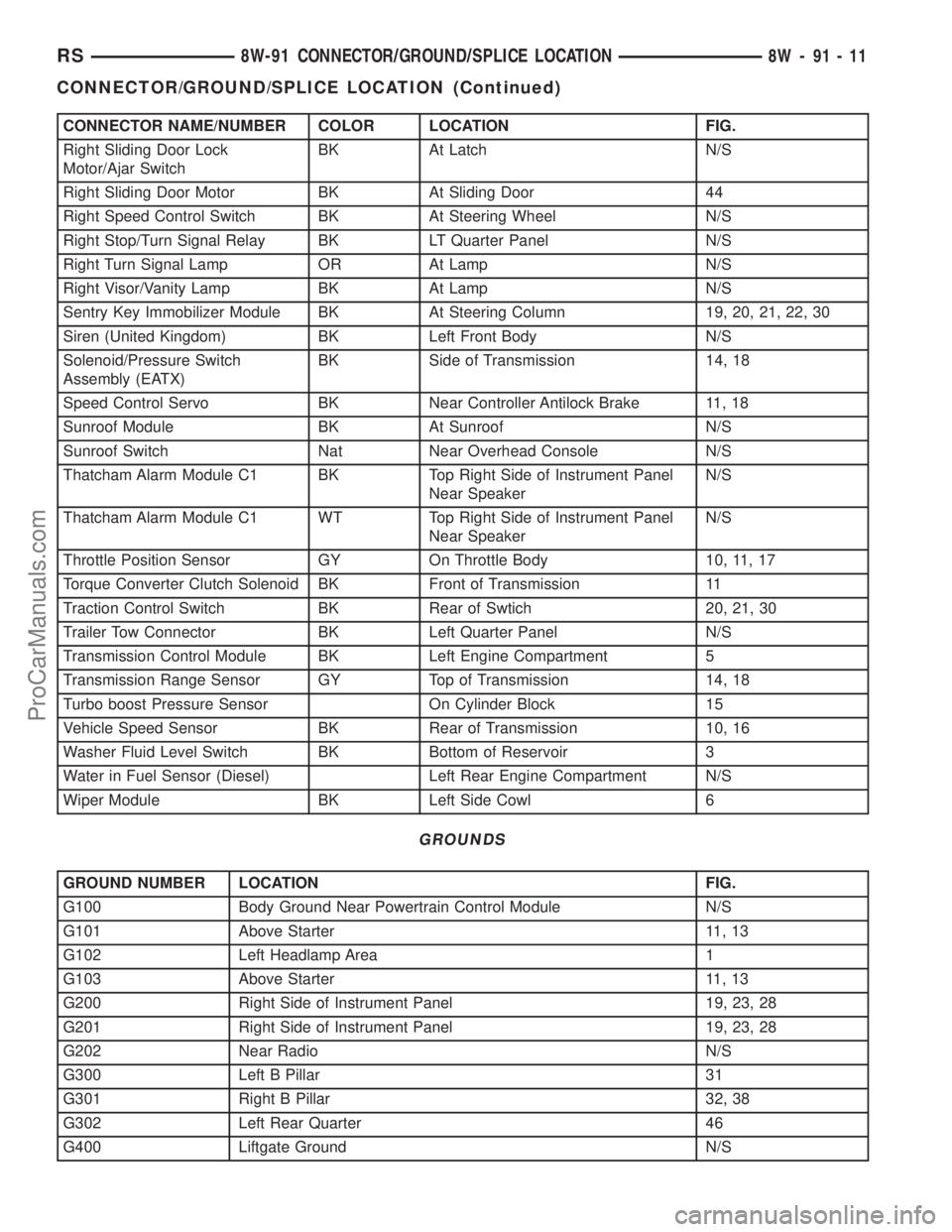
CONNECTOR NAME/NUMBER COLOR LOCATION FIG.
Right Sliding Door Lock
Motor/Ajar SwitchBK At Latch N/S
Right Sliding Door Motor BK At Sliding Door 44
Right Speed Control Switch BK At Steering Wheel N/S
Right Stop/Turn Signal Relay BK LT Quarter Panel N/S
Right Turn Signal Lamp OR At Lamp N/S
Right Visor/Vanity Lamp BK At Lamp N/S
Sentry Key Immobilizer Module BK At Steering Column 19, 20, 21, 22, 30
Siren (United Kingdom) BK Left Front Body N/S
Solenoid/Pressure Switch
Assembly (EATX)BK Side of Transmission 14, 18
Speed Control Servo BK Near Controller Antilock Brake 11, 18
Sunroof Module BK At Sunroof N/S
Sunroof Switch Nat Near Overhead Console N/S
Thatcham Alarm Module C1 BK Top Right Side of Instrument Panel
Near SpeakerN/S
Thatcham Alarm Module C1 WT Top Right Side of Instrument Panel
Near SpeakerN/S
Throttle Position Sensor GY On Throttle Body 10, 11, 17
Torque Converter Clutch Solenoid BK Front of Transmission 11
Traction Control Switch BK Rear of Swtich 20, 21, 30
Trailer Tow Connector BK Left Quarter Panel N/S
Transmission Control Module BK Left Engine Compartment 5
Transmission Range Sensor GY Top of Transmission 14, 18
Turbo boost Pressure Sensor On Cylinder Block 15
Vehicle Speed Sensor BK Rear of Transmission 10, 16
Washer Fluid Level Switch BK Bottom of Reservoir 3
Water in Fuel Sensor (Diesel) Left Rear Engine Compartment N/S
Wiper Module BK Left Side Cowl 6
GROUNDS
GROUND NUMBER LOCATION FIG.
G100 Body Ground Near Powertrain Control Module N/S
G101 Above Starter 11, 13
G102 Left Headlamp Area 1
G103 Above Starter 11, 13
G200 Right Side of Instrument Panel 19, 23, 28
G201 Right Side of Instrument Panel 19, 23, 28
G202 Near Radio N/S
G300 Left B Pillar 31
G301 Right B Pillar 32, 38
G302 Left Rear Quarter 46
G400 Liftgate Ground N/S
RS8W-91 CONNECTOR/GROUND/SPLICE LOCATION8W-91-11
CONNECTOR/GROUND/SPLICE LOCATION (Continued)
ProCarManuals.com
Page 1265 of 2177
(1) Inspect air cleaner, induction system and
intake manifold to insure system is dry and clear of
foreign material.
(2) Remove negative battery cable.
(3) Place a shop towel around the spark plugs
when removing them from the engine. This will catch
any fluid that may possibly be in the cylinder under
pressure.
(4) With all spark plugs removed, rotate engine
crankshaft using a breaker bar and socket.
(5) Identify the fluid in the cylinder(s) (i.e., cool-
ant, fuel, oil or other).
(6) Make sure all fluid has been removed from the
cylinders. Inspect engine for damage (i.e., connecting
rods, pistons, valves, etc.)
(7) Repair engine or components as necessary to
prevent this problem from re-occurring.
CAUTION: Squirt approximately one teaspoon of oil
into the cylinders, rotate engine to lubricate the cyl-
inder walls to prevent damage on restart.
(8) Install new spark plugs.
(9) Drain engine oil and remove oil filter.
(10) Install a new oil filter.
(11) Fill engine with specified amount of approved
oil.
(12) Connect negative battery cable.
(13) Start engine and check for any leaks.
STANDARD PROCEDURE - REPAIR OF
DAMAGED OR WORN THREADS
Damaged or worn threads (excluding spark plug
and camshaft bearing cap attaching threads) can be
repaired. Essentially, this repair consists of drilling
out worn or damaged threads, tapping the hole with
a special Heli-Coil Tap, (or equivalent) and installing
an insert into the tapped hole. This brings the hole
back to its original thread size.
CAUTION: Be sure that the tapped holes maintain
the original center line.
Heli-Coil tools and inserts are readily available
from automotive parts jobbers.
STANDARD PROCEDURE - ENGINE CORE AND
OIL GALLERY PLUGS
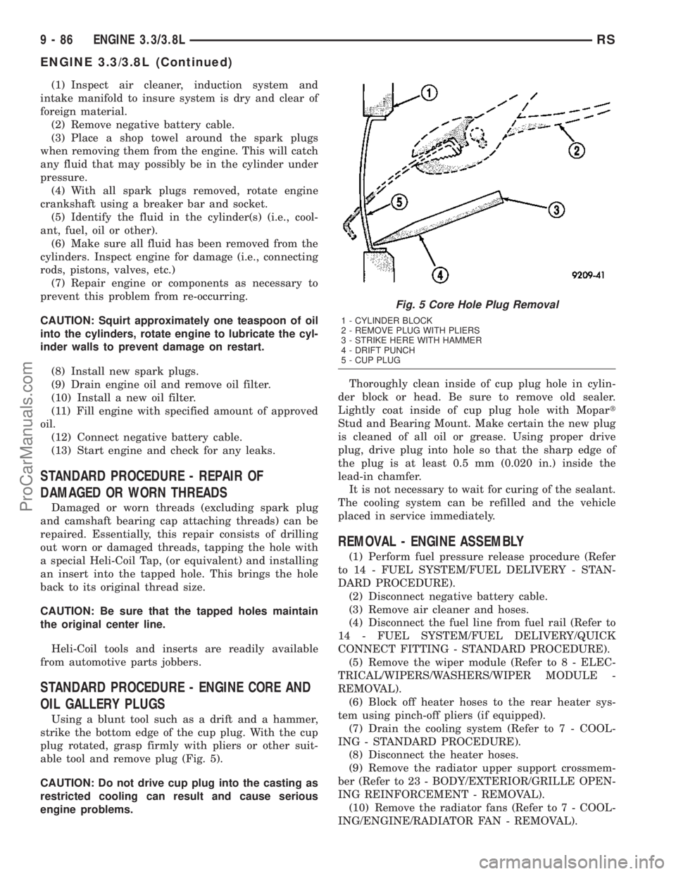
Using a blunt tool such as a drift and a hammer,
strike the bottom edge of the cup plug. With the cup
plug rotated, grasp firmly with pliers or other suit-
able tool and remove plug (Fig. 5).
CAUTION: Do not drive cup plug into the casting as
restricted cooling can result and cause serious
engine problems.Thoroughly clean inside of cup plug hole in cylin-
der block or head. Be sure to remove old sealer.
Lightly coat inside of cup plug hole with Mopart
Stud and Bearing Mount. Make certain the new plug
is cleaned of all oil or grease. Using proper drive
plug, drive plug into hole so that the sharp edge of
the plug is at least 0.5 mm (0.020 in.) inside the
lead-in chamfer.
It is not necessary to wait for curing of the sealant.
The cooling system can be refilled and the vehicle
placed in service immediately.
REMOVAL - ENGINE ASSEMBLY
(1) Perform fuel pressure release procedure (Refer
to 14 - FUEL SYSTEM/FUEL DELIVERY - STAN-
DARD PROCEDURE).
(2) Disconnect negative battery cable.
(3) Remove air cleaner and hoses.
(4) Disconnect the fuel line from fuel rail (Refer to
14 - FUEL SYSTEM/FUEL DELIVERY/QUICK
CONNECT FITTING - STANDARD PROCEDURE).
(5) Remove the wiper module (Refer to 8 - ELEC-
TRICAL/WIPERS/WASHERS/WIPER MODULE -
REMOVAL).
(6) Block off heater hoses to the rear heater sys-
tem using pinch-off pliers (if equipped).
(7) Drain the cooling system (Refer to 7 - COOL-
ING - STANDARD PROCEDURE).
(8) Disconnect the heater hoses.
(9) Remove the radiator upper support crossmem-
ber (Refer to 23 - BODY/EXTERIOR/GRILLE OPEN-
ING REINFORCEMENT - REMOVAL).
(10) Remove the radiator fans (Refer to 7 - COOL-
ING/ENGINE/RADIATOR FAN - REMOVAL).
Fig. 5 Core Hole Plug Removal
1 - CYLINDER BLOCK
2 - REMOVE PLUG WITH PLIERS
3 - STRIKE HERE WITH HAMMER
4 - DRIFT PUNCH
5 - CUP PLUG
9 - 86 ENGINE 3.3/3.8LRS
ENGINE 3.3/3.8L (Continued)
ProCarManuals.com
Page 1435 of 2177
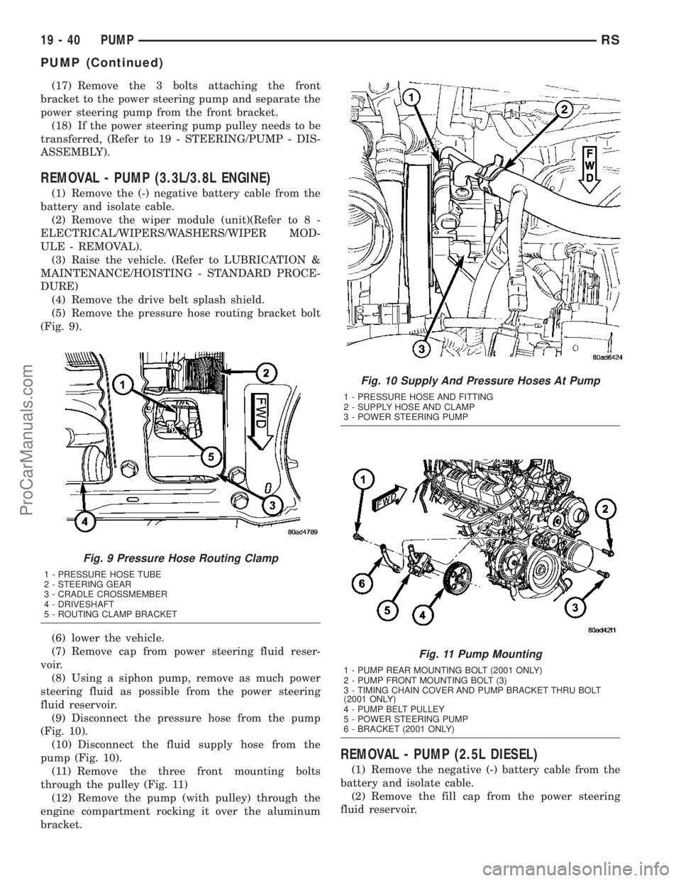
(17) Remove the 3 bolts attaching the front
bracket to the power steering pump and separate the
power steering pump from the front bracket.
(18) If the power steering pump pulley needs to be
transferred, (Refer to 19 - STEERING/PUMP - DIS-
ASSEMBLY).
REMOVAL - PUMP (3.3L/3.8L ENGINE)
(1) Remove the (-) negative battery cable from the
battery and isolate cable.
(2) Remove the wiper module (unit)(Refer to 8 -
ELECTRICAL/WIPERS/WASHERS/WIPER MOD-
ULE - REMOVAL).
(3) Raise the vehicle. (Refer to LUBRICATION &
MAINTENANCE/HOISTING - STANDARD PROCE-
DURE)
(4) Remove the drive belt splash shield.
(5) Remove the pressure hose routing bracket bolt
(Fig. 9).
(6) lower the vehicle.
(7) Remove cap from power steering fluid reser-
voir.
(8) Using a siphon pump, remove as much power
steering fluid as possible from the power steering
fluid reservoir.
(9) Disconnect the pressure hose from the pump
(Fig. 10).
(10) Disconnect the fluid supply hose from the
pump (Fig. 10).
(11) Remove the three front mounting bolts
through the pulley (Fig. 11)
(12) Remove the pump (with pulley) through the
engine compartment rocking it over the aluminum
bracket.
REMOVAL - PUMP (2.5L DIESEL)
(1) Remove the negative (-) battery cable from the
battery and isolate cable.
(2) Remove the fill cap from the power steering
fluid reservoir.
Fig. 9 Pressure Hose Routing Clamp
1 - PRESSURE HOSE TUBE
2 - STEERING GEAR
3 - CRADLE CROSSMEMBER
4 - DRIVESHAFT
5 - ROUTING CLAMP BRACKET
Fig. 10 Supply And Pressure Hoses At Pump
1 - PRESSURE HOSE AND FITTING
2 - SUPPLY HOSE AND CLAMP
3 - POWER STEERING PUMP
Fig. 11 Pump Mounting
1 - PUMP REAR MOUNTING BOLT (2001 ONLY)
2 - PUMP FRONT MOUNTING BOLT (3)
3 - TIMING CHAIN COVER AND PUMP BRACKET THRU BOLT
(2001 ONLY)
4 - PUMP BELT PULLEY
5 - POWER STEERING PUMP
6 - BRACKET (2001 ONLY)
19 - 40 PUMPRS
PUMP (Continued)
ProCarManuals.com
Page 1438 of 2177
INSTALLATION - PUMP (3.3L/3.8L ENGINE)
(1) Install power steering pump back in vehicle
using the reverse order of its removal through the
engine compartment of the vehicle.
(2) Install the power steering pump on its mount-
ing bracket.
(3) Install the 3 front power steering pump mount-
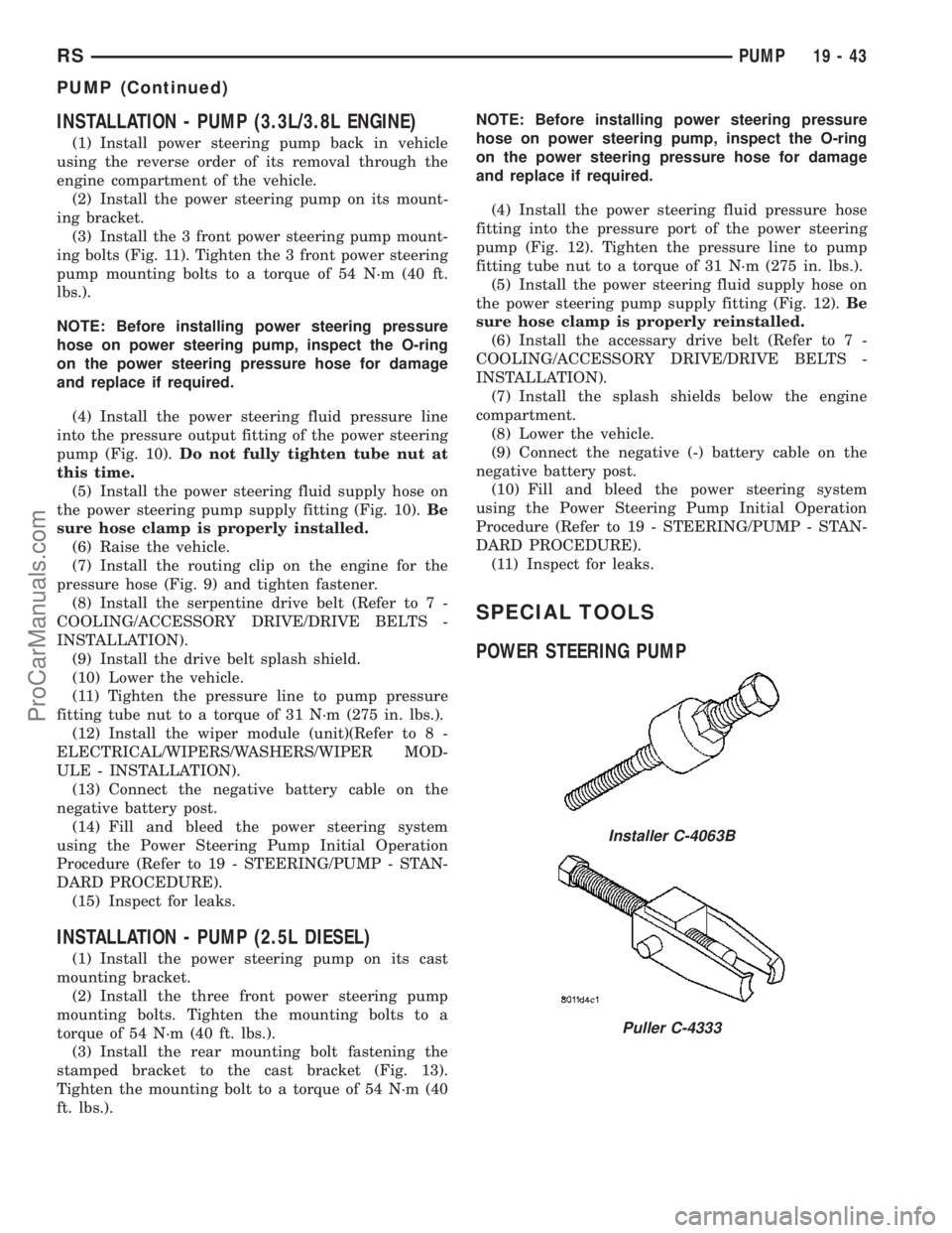
ing bolts (Fig. 11). Tighten the 3 front power steering
pump mounting bolts to a torque of 54 N´m (40 ft.
lbs.).
NOTE: Before installing power steering pressure
hose on power steering pump, inspect the O-ring
on the power steering pressure hose for damage
and replace if required.
(4) Install the power steering fluid pressure line
into the pressure output fitting of the power steering
pump (Fig. 10).Do not fully tighten tube nut at
this time.
(5) Install the power steering fluid supply hose on
the power steering pump supply fitting (Fig. 10).Be
sure hose clamp is properly installed.
(6) Raise the vehicle.
(7) Install the routing clip on the engine for the
pressure hose (Fig. 9) and tighten fastener.
(8) Install the serpentine drive belt (Refer to 7 -
COOLING/ACCESSORY DRIVE/DRIVE BELTS -
INSTALLATION).
(9) Install the drive belt splash shield.
(10) Lower the vehicle.
(11) Tighten the pressure line to pump pressure
fitting tube nut to a torque of 31 N´m (275 in. lbs.).
(12) Install the wiper module (unit)(Refer to 8 -
ELECTRICAL/WIPERS/WASHERS/WIPER MOD-
ULE - INSTALLATION).
(13) Connect the negative battery cable on the
negative battery post.
(14) Fill and bleed the power steering system
using the Power Steering Pump Initial Operation
Procedure (Refer to 19 - STEERING/PUMP - STAN-
DARD PROCEDURE).
(15) Inspect for leaks.
INSTALLATION - PUMP (2.5L DIESEL)
(1) Install the power steering pump on its cast
mounting bracket.
(2) Install the three front power steering pump
mounting bolts. Tighten the mounting bolts to a
torque of 54 N´m (40 ft. lbs.).
(3) Install the rear mounting bolt fastening the
stamped bracket to the cast bracket (Fig. 13).
Tighten the mounting bolt to a torque of 54 N´m (40
ft. lbs.).NOTE: Before installing power steering pressure
hose on power steering pump, inspect the O-ring
on the power steering pressure hose for damage
and replace if required.
(4) Install the power steering fluid pressure hose
fitting into the pressure port of the power steering
pump (Fig. 12). Tighten the pressure line to pump
fitting tube nut to a torque of 31 N´m (275 in. lbs.).
(5) Install the power steering fluid supply hose on
the power steering pump supply fitting (Fig. 12).Be
sure hose clamp is properly reinstalled.
(6) Install the accessary drive belt (Refer to 7 -
COOLING/ACCESSORY DRIVE/DRIVE BELTS -
INSTALLATION).
(7) Install the splash shields below the engine
compartment.
(8) Lower the vehicle.
(9) Connect the negative (-) battery cable on the
negative battery post.
(10) Fill and bleed the power steering system
using the Power Steering Pump Initial Operation
Procedure (Refer to 19 - STEERING/PUMP - STAN-
DARD PROCEDURE).
(11) Inspect for leaks.
SPECIAL TOOLS
POWER STEERING PUMP
Installer C-4063B
Puller C-4333
RSPUMP19-43
PUMP (Continued)
ProCarManuals.com
Page 1450 of 2177
OPERATION
The Transfer Unit provides the power to the rear
wheels through a hypoid ring gear and pinion set.
DIAGNOSIS AND TESTING
SEAL IDENTIFICATION
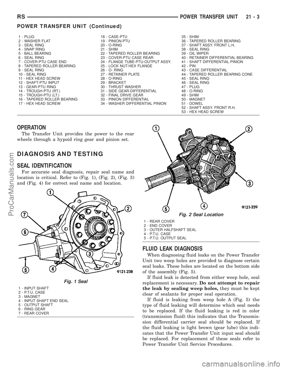
For accurate seal diagnosis, repair seal name and
location is critical. Refer to (Fig. 1), (Fig. 2), (Fig. 3)
and (Fig. 4) for correct seal name and location.
FLUID LEAK DIAGNOSIS
When diagnosing fluid leaks on the Power Transfer
Unit two weep holes are provided to diagnose certain
seal leaks. These holes are located on the bottom side
of the assembly (Fig. 5).
If fluid leak is detected from either weep hole, seal
replacement is necessary.Do not attempt to repair
the leak by sealing weep holes,they must be kept
clear of sealants for proper seal operation.
If fluid is leaking from weep hole A (Fig. 5) the
type of fluid leaking will determine which seal needs
to be replaced. If the fluid leaking is red in color
(transmission fluid) this indicates that the Transmis-
sion differential carrier seal should be replaced. If
the fluid leaking is light brown (gear lube) this indi-
cates that the Power Transfer Unit input seal should
be replaced. For replacement of these seals refer to
Power Transfer Unit Service Procedures.
1 - PLUG 18 - CASE-PTU 35 - SHIM
2 - WASHER FLAT 19 - PINION-PTU 36 - TAPERED ROLLER BEARING
3 - SEAL RING 20 - O-RING 37 - SHAFT ASSY. FRONT L.H.
4 - SNAP RING 21 - SHIM 38 - SEAL RING
5 - BALL BEARING 22 - TAPERED ROLLER BEARING 39 - OIL WIPER
6 - SEAL RING 23 - COVER-PTU CASE REAR 40 - RETAINER DIFFERENTIAL BEARING
7 - COVER-PTU CASE END 24 - FLANGE TUBE-PTU-OUTPUT ASSY. 41 - SHAFT DIFFERENTIAL PINION
8 - TAPERED ROLLER BEARING 25 - LOCK NUT-HEX FLANGE 42 - PIN
9 - SEAL RING 26 - O- RING 43 - CASE DIFFERENTIAL
10 - SEAL RING 27 - RETAINER PLATE 44 - TAPERED ROLLER BEARING CONE
11 - HEX HEAD SCREW 28 - O-RING 45 - SEAL RING
12 - SHAFT-PTU INPUT 29 - BRACKET 46 - SEAL RING
13 - GEAR-PTU RING 30 - THRUST WASHER 47 - PLUG
14 - TROUGH-PTU (RT.) 31 - SIDE GEAR-DIFFERENTIAL 48 - O-RING
15 - TROUGH-PTU (LT.) 32 - FINAL DRIVE GEAR 49 - SHIM
16 - TAPERED ROLLER BEARING 33 - PINION DIFFERENTIAL 50 - MAGNET
17 - HEX HEAD SCREW 34 - WASHER DIFFERENTIAL PINION 51 - DOWEL
52 - SHAFT ASSY. FRONT R.H.
53 - HEX HEAD SCREW
Fig. 1 Seal
1 - INPUT SHAFT
2 - P.T.U. CASE
3 - MAGNET
4 - INPUT SHAFT END SEAL
5 - OUTPUT SHAFT
6 - RING GEAR
7 - REAR COVER
Fig. 2 Seal Location
1 - REAR COVER
2 - END COVER
3 - OUTER HALFSHAFT SEAL
4 - P.T.U. CASE
5 - P.T.U. OUTPUT SEAL
RSPOWER TRANSFER UNIT21-3
POWER TRANSFER UNIT (Continued)
ProCarManuals.com
Page 2158 of 2177
LIFTGATE MOTOR - OPERATION.........8N-15
LIFTGATE MOTOR - REMOVAL..........8N-15
LIFTGATE SIDE - INSTALLATION.........23-43
LIFTGATE SIDE - REMOVAL............23-43
LIFTGATE SILL PLATE - INSTALLATION . . . 23-77
LIFTGATE SILL PLATE - REMOVAL.......23-77
LIFTGATE SPOILER - INSTALLATION......23-41
LIFTGATE SPOILER - REMOVAL.........23-41
LIFTGATE SYSTEM - DESCRIPTION,
POWER.............................8N-2
LIFTGATE SYSTEM - DIAGNOSIS AND
TESTING, POWER.....................8N-4
LIFTGATE SYSTEM - OPERATION,
POWER.............................8N-3
LIMITS - DESCRIPTION, HIGH AND LOW . . . 25-8
LINE - INSTALLATION, DISCHARGE......24-69
LINE - INSTALLATION, FUEL...........24-110
LINE - INSTALLATION, LIQUID..........24-82
LINE - INSTALLATION, SUCTION . . . 24-102,24-91
LINE - REMOVAL, DISCHARGE..........24-68
LINE - REMOVAL, FUEL...............24-109
LINE - REMOVAL, LIQUID..............24-80
LINE - REMOVAL, SUCTION......24-101,24-90
LINE AND TERMINAL REPAIR -
STANDARD PROCEDURE, GRID..........8G-3
LINE EXTENSION - INSTALLATION,
EVAPORATOR.......................24-96
LINE EXTENSION - REMOVAL,
EVAPORATOR.......................24-95
LINE REPAIR REAR - STANDARD
PROCEDURE, GRID....................8G-2
LINES - DESCRIPTION, OIL COOLER.....9-138
LINES - DESCRIPTION, UNDERBODY....24-103
LINES - INSTALLATION, OIL COOLER.....9-138
LINES - INSTALLATION, REAR AIR
CONDITIONING.....................24-105
LINES - INSTALLATION, REAR HEATER . . 24-105
LINES - INSTALLATION, TRANSMISSION
OIL COOLER.........................7-38
LINES - OPERATION, OIL COOLER.......9-138
LINES - OPERATION, UNDERBODY......24-103
LINES - REMOVAL, OIL COOLER........9-138
LINES - REMOVAL, REAR AIR
CONDITIONING.....................24-104
LINES - REMOVAL, REAR HEATER......24-104
LINES - REMOVAL, TRANSMISSION OIL
COOLER.............................7-38
LINES/HOSES AND CLAMPS -
DESCRIPTION, FUEL...................14-6
LINING - INSPECTION, REAR DRUM
BRAKE SHOE.........................5-22
LINK - DESCRIPTION, TRD............21-249
LINK - INSTALLATION, FUEL FILL DOOR
BLOCKER LOCKOUT..................23-53
LINK - OPERATION, TRD..............21-249
LINK - REMOVAL, FUEL FILL DOOR
BLOCKER LOCKOUT..................23-52
LINK CONNECTOR - DESCRIPTION, DATA . . 8E-6
LINK CONNECTOR - OPERATION, DATA....8E-7
LINK ROD - DESCRIPTION, LIFT GEAR . . . 8N-16
LINK ROD - INSTALLATION, LIFT GEAR . . . 8N-16
LINK ROD - OPERATION, LIFT GEAR.....8N-16
LINK ROD - REMOVAL, LIFT GEAR.......8N-16
LINKAGE - INSTALLATION, WIPER.......8R-18
LINKAGE - REMOVAL, WIPER...........8R-17
LIQUID LINE - INSTALLATION...........24-82
LIQUID LINE - REMOVAL
..............24-80
LOADS - STANDARD PROCEDURE,
TESTING FOR A SHORT TO GROUND
ON FUSES POWERING SEVERAL
.....8W-01-10
LOCATION - DESCRIPTION, CONNECTOR/
GROUND/SPLICE
...................8W-91-1
LOCATIONS - DESCRIPTION, FLUID
FILL/CHECK
...........................0-7
LOCATIONS - SPECIFICATIONS, BODY
SEALING
..........................23-127
LOCATIONS - SPECIFICATIONS,
STRUCTURAL ADHESIVE
..............23-153
LOCATIONS - SPECIFICATIONS, WELD
. . . 23-161
LOCK ASSEMBLY - INSTALLATION,
LATCH
.............................23-27
LOCK ASSEMBLY - REMOVAL, LATCH
....23-26
LOCK CYLINDER - INSTALLATION
. . 23-20,23-41
LOCK CYLINDER - REMOVAL
......23-19,23-41
LOCK CYLINDER HOUSING -
INSTALLATION
.......................19-19
LOCK CYLINDER HOUSING - REMOVAL
. . . 19-17LOCK MOTOR - DIAGNOSIS AND
TESTING, DOOR.....................8N-41
LOCK MOTOR - INSTALLATION, SLIDING
DOOR.............................8N-44
LOCK MOTOR - REMOVAL, SLIDING
DOOR.............................8N-44
LOCK SWITCH - DESCRIPTION, DOOR
CYLINDER..........................8N-40
LOCK SWITCH - DIAGNOSIS AND
TESTING, DOOR.....................8N-41
LOCK SWITCH - DIAGNOSIS AND
TESTING, DOOR CYLINDER............8N-40
LOCK SWITCH - INSTALLATION, DOOR . . . 8N-42
LOCK SWITCH - INSTALLATION, DOOR
CYLINDER..........................8N-41
LOCK SWITCH - OPERATION, DOOR
CYLINDER..........................8N-40
LOCK SWITCH - REMOVAL, DOOR.......8N-42
LOCK SWITCH - REMOVAL, DOOR
CYLINDER..........................8N-41
LOCKED ENGINE - STANDARD
PROCEDURE, HYDROSTATIC.........9-10,9-85
LOCK/LATCH - INSTALLATION, UNDER
SEAT STORAGE BIN.................23-104
LOCK/LATCH - REMOVAL, UNDER SEAT
STORAGE BIN......................23-104
LOCKOUT LINK - INSTALLATION, FUEL
FILL DOOR BLOCKER.................23-53
LOCKOUT LINK - REMOVAL, FUEL FILL
DOOR BLOCKER.....................23-52
LOCKS - DESCRIPTION, POWER........8N-38
LOCKS - OPERATION, POWER..........8N-39
LOUVER - INSTALLATION, REAR HVAC . . . 23-79
LOUVER - REMOVAL, REAR HVAC.......23-79
LOW LIMITS - DESCRIPTION, HIGH.......25-8
LOWER - CLEANING, INTAKE MANIFOLD . . 9-148
LOWER - INSPECTION, INTAKE
MANIFOLD......................9-148,9-60
LOWER - INSTALLATION, INTAKE
MANIFOLD...........................9-60
LOWER - INSTALLATION, SHROUD.......19-22
LOWER - REMOVAL, INTAKE MANIFOLD . . . 9-60
LOWER - REMOVAL, SHROUD..........19-21
LOWER BALL JOINT - DESCRIPTION......2-10
LOWER BALL JOINT - DIAGNOSIS AND
TESTING............................2-10
LOWER BALL JOINT - OPERATION........2-10
LOWER CONSOLE - INSTALLATION......23-68
LOWER CONSOLE - REMOVAL..........23-68
LOWER CONTROL ARM - DESCRIPTION . . . 2-12
LOWER CONTROL ARM - INSPECTION.....2-14
LOWER CONTROL ARM - INSTALLATION . . . 2-15
LOWER CONTROL ARM - OPERATION.....2-12
LOWER CONTROL ARM - REMOVAL......2-12
LOWER CONTROL ARM (REAR BUSHING
- HYDRO) - ASSEMBLY.................2-14
LOWER CONTROL ARM (REAR BUSHING
- HYDRO) - DISASSEMBLY..............2-14
LOWER CONTROL ARM (REAR BUSHING
- STANDARD) - ASSEMBLY..............2-14
LOWER CONTROL ARM (REAR BUSHING
- STANDARD) - DISASSEMBLY...........2-13
LOWER DRIVE UNIT - DESCRIPTION.....8N-32
LOWER DRIVE UNIT - INSTALLATION....8N-33
LOWER DRIVE UNIT - OPERATION.......8N-32
LOWER DRIVE UNIT - REMOVAL
........8N-33
LOWER DRIVE UNIT TRACK & RACK -
DESCRIPTION
.......................8N-34
LOWER DRIVE UNIT TRACK & RACK -
INSTALLATION
......................8N-34
LOWER DRIVE UNIT TRACK & RACK -
OPERATION
.........................8N-34
LOWER DRIVE UNIT TRACK & RACK -
REMOVAL
..........................8N-34
LOWER EXTENSION TRIM -
INSTALLATION, A-PILLAR
..............23-73
LOWER EXTENSION TRIM - REMOVAL,
A-PILLAR
...........................23-73
LOWER HINGE - INSTALLATION
.........23-28
LOWER HINGE - REMOVAL
.............23-28
LOWER INSTRUMENT PANEL -
INSTALLATION
.......................23-68
LOWER INSTRUMENT PANEL -
REMOVAL
..........................23-68
LOWER INTAKE MANIFOLD -
INSTALLATION
.......................9-149
LOWER INTAKE MANIFOLD - REMOVAL
. . . 9-148LOWER STEERING COLUMN COVER -
INSTALLATION.......................23-69
LOWER STEERING COLUMN COVER -
REMOVAL..........................23-69
LOWER TRIM - INSTALLATION,
B-PILLAR...........................23-74
LOWER TRIM - REMOVAL, B-PILLAR.....23-73
LUBRICANTS - DESCRIPTION, ENGINE
OIL .................................0-1
LUBRICATION - DESCRIPTION......9-136,9-52
LUBRICATION - OPERATION........9-136,9-52
LUBRICATION - STANDARD PROCEDURE....2-2
LUBRICATION POINTS - DESCRIPTION......0-7
LUBRICATION, SPECIFICATIONS - BODY . . 23-12
LUGGAGE RACK CROSSBAR -
INSTALLATION.......................23-56
LUGGAGE RACK CROSSBAR - REMOVAL . . 23-55
LUGGAGE RACK RISER - INSTALLATION . . 23-55
LUGGAGE RACK RISER - REMOVAL......23-54
LUMBAR SUPPORT - INSTALLATION....23-104
LUMBAR SUPPORT - REMOVAL........23-104
LWB - INSTALLATION, SEAT BELT &
RETRACTOR - SECOND ROW - RIGHT
OUTBOARD WITH REAR HVAC..........8O-15
LWB - REMOVAL, SEAT BELT &
RETRACTOR - SECOND ROW - RIGHT
OUTBOARD WITH REAR HVAC..........8O-15
MACHINING - STANDARD PROCEDURE,
BRAKE ROTOR.......................5-53
MAIN BEARING FITTING - STANDARD
PROCEDURE..........................9-123
MAIN BEARINGS - INSTALLATION,
CRANKSHAFT.......................9-124
MAIN BEARINGS - REMOVAL,
CRANKSHAFT.......................9-124
MAINTENANCE SCHEDULES -
DESCRIPTION.........................0-7
MANAGER - DESCRIPTION, TASK........25-24
MANAGER - OPERATION, TASK.........25-24
MANIFOLD - CLEANING, EXHAUST........9-61
MANIFOLD - DESCRIPTION, INTAKE . . 9-144,9-58
MANIFOLD - INSPECTION, EXHAUST......9-61
MANIFOLD - INSTALLATION, EXHAUST....9-61
MANIFOLD - INSTALLATION, LOWER
INTAKE ............................9-149
MANIFOLD - INSTALLATION, UPPER
INTAKE ............................9-147
MANIFOLD - LEFT - CLEANING,
EXHAUST...........................9-152
MANIFOLD - LEFT - INSPECTION,
EXHAUST...........................9-152
MANIFOLD - LEFT - INSTALLATION,
EXHAUST...........................9-152
MANIFOLD - LEFT - REMOVAL, EXHAUST . 9-152
MANIFOLD - LOWER - CLEANING,
INTAKE ............................9-148
MANIFOLD - LOWER - INSPECTION,
INTAKE ........................9-148,9-60
MANIFOLD - LOWER - INSTALLATION,
INTAKE .............................9-60
MANIFOLD - LOWER - REMOVAL,
INTAKE .............................9-60
MANIFOLD - REMOVAL, EXHAUST........9-61
MANIFOLD - REMOVAL, LOWER INTAKE . . 9-148
MANIFOLD - REMOVAL, UPPER INTAKE . . . 9-145
MANIFOLD - RIGHT - CLEANING,
EXHAUST...........................9-151
MANIFOLD - RIGHT - INSPECTION,
EXHAUST...........................9-151
MANIFOLD - RIGHT - INSTALLATION,
EXHAUST...........................9-151
MANIFOLD - RIGHT - REMOVAL,
EXHAUST...........................9-150
MANIFOLD - UPPER - INSPECTION,
INTAKE .............................9-59
MANIFOLD - UPPER - INSTALLATION,
INTAKE .............................9-59
MANIFOLD - UPPER - REMOVAL, INTAKE . . 9-58
MANIFOLD LEAKS - DIAGNOSIS AND
TESTING, INTAKE
................9-145,9-58
MANIFOLD STRIPPED THREAD REPAIR -
STANDARD PROCEDURE
...............9-145
MANIFOLD VACUUM PORT REPAIR -
STANDARD PROCEDURE, INTAKE
........9-145
MANUAL - INSTALLATION, WINDOW
REGULATOR
........................23-23
MANUAL - REMOVAL, WINDOW
REGULATOR
........................23-23
RSINDEX19
Description Group-Page Description Group-Page Description Group-Page
ProCarManuals.com