2003 CHRYSLER CARAVAN gas type
[x] Cancel search: gas typePage 1503 of 2177
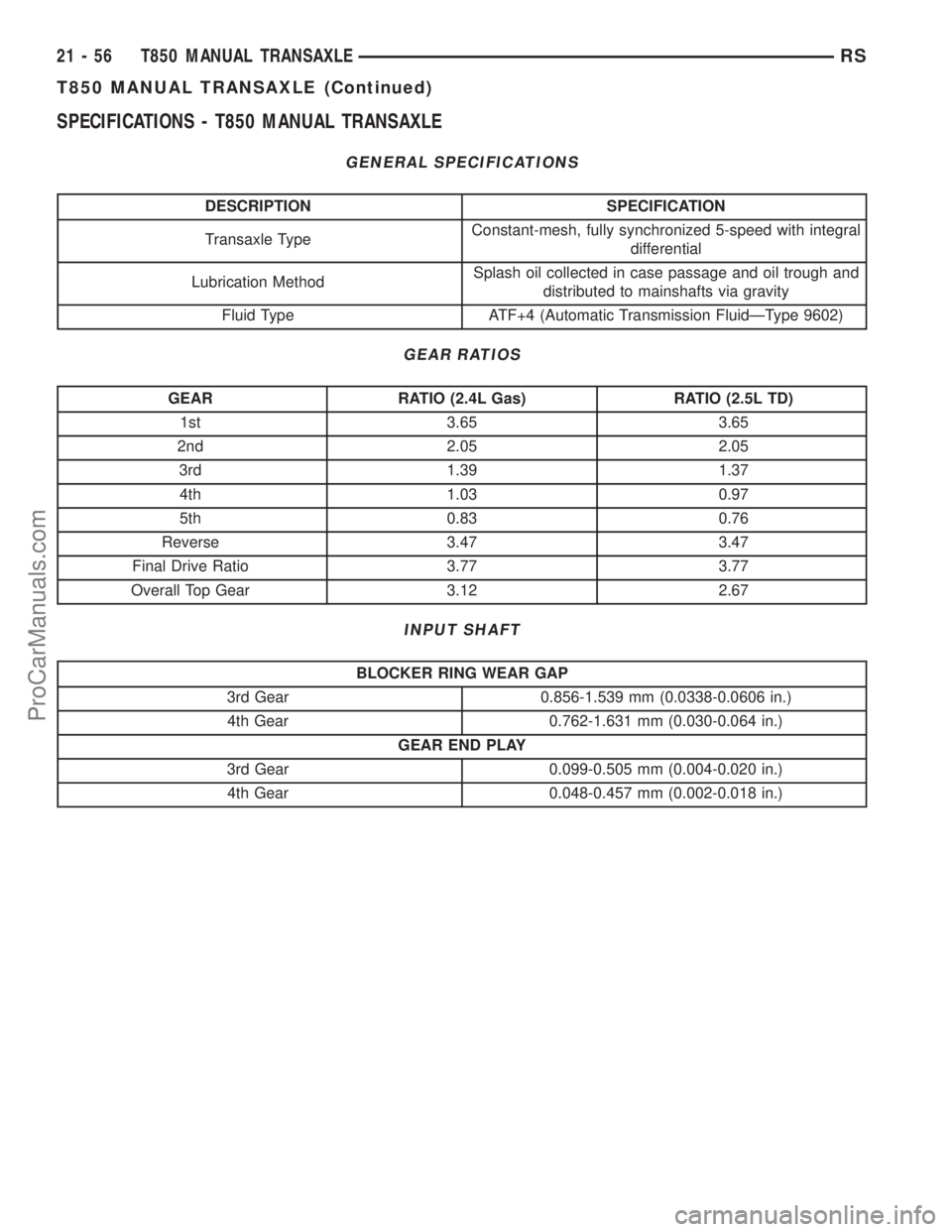
SPECIFICATIONS - T850 MANUAL TRANSAXLE
GENERAL SPECIFICATIONS
DESCRIPTION SPECIFICATION
Transaxle TypeConstant-mesh, fully synchronized 5-speed with integral
differential
Lubrication MethodSplash oil collected in case passage and oil trough and
distributed to mainshafts via gravity
Fluid Type ATF+4 (Automatic Transmission FluidÐType 9602)
GEAR RATIOS
GEAR RATIO (2.4L Gas) RATIO (2.5L TD)
1st 3.65 3.65
2nd 2.05 2.05
3rd 1.39 1.37
4th 1.03 0.97
5th 0.83 0.76
Reverse 3.47 3.47
Final Drive Ratio 3.77 3.77
Overall Top Gear 3.12 2.67
INPUT SHAFT
BLOCKER RING WEAR GAP
3rd Gear 0.856-1.539 mm (0.0338-0.0606 in.)
4th Gear 0.762-1.631 mm (0.030-0.064 in.)
GEAR END PLAY
3rd Gear 0.099-0.505 mm (0.004-0.020 in.)
4th Gear 0.048-0.457 mm (0.002-0.018 in.)
21 - 56 T850 MANUAL TRANSAXLERS
T850 MANUAL TRANSAXLE (Continued)
ProCarManuals.com
Page 1735 of 2177
DIAGNOSIS AND TESTING
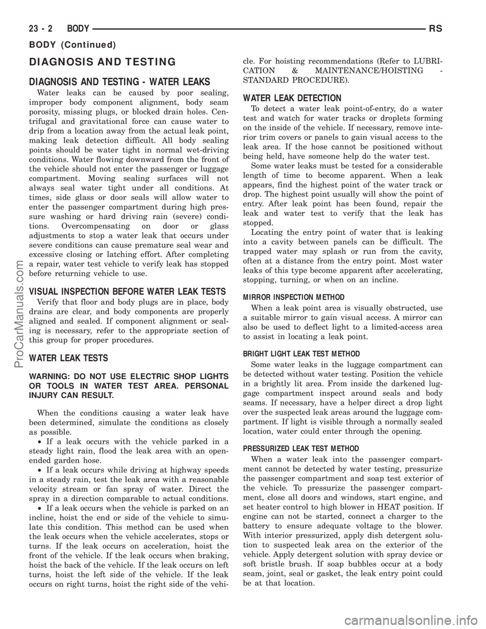
DIAGNOSIS AND TESTING - WATER LEAKS
Water leaks can be caused by poor sealing,
improper body component alignment, body seam
porosity, missing plugs, or blocked drain holes. Cen-
trifugal and gravitational force can cause water to
drip from a location away from the actual leak point,
making leak detection difficult. All body sealing
points should be water tight in normal wet-driving
conditions. Water flowing downward from the front of
the vehicle should not enter the passenger or luggage
compartment. Moving sealing surfaces will not
always seal water tight under all conditions. At
times, side glass or door seals will allow water to
enter the passenger compartment during high pres-
sure washing or hard driving rain (severe) condi-
tions. Overcompensating on door or glass
adjustments to stop a water leak that occurs under
severe conditions can cause premature seal wear and
excessive closing or latching effort. After completing
a repair, water test vehicle to verify leak has stopped
before returning vehicle to use.
VISUAL INSPECTION BEFORE WATER LEAK TESTS
Verify that floor and body plugs are in place, body
drains are clear, and body components are properly
aligned and sealed. If component alignment or seal-
ing is necessary, refer to the appropriate section of
this group for proper procedures.
WATER LEAK TESTS
WARNING: DO NOT USE ELECTRIC SHOP LIGHTS
OR TOOLS IN WATER TEST AREA. PERSONAL
INJURY CAN RESULT.
When the conditions causing a water leak have
been determined, simulate the conditions as closely
as possible.
²If a leak occurs with the vehicle parked in a
steady light rain, flood the leak area with an open-
ended garden hose.
²If a leak occurs while driving at highway speeds
in a steady rain, test the leak area with a reasonable
velocity stream or fan spray of water. Direct the
spray in a direction comparable to actual conditions.
²If a leak occurs when the vehicle is parked on an
incline, hoist the end or side of the vehicle to simu-
late this condition. This method can be used when
the leak occurs when the vehicle accelerates, stops or
turns. If the leak occurs on acceleration, hoist the
front of the vehicle. If the leak occurs when braking,
hoist the back of the vehicle. If the leak occurs on left
turns, hoist the left side of the vehicle. If the leak
occurs on right turns, hoist the right side of the vehi-cle. For hoisting recommendations (Refer to LUBRI-
CATION & MAINTENANCE/HOISTING -
STANDARD PROCEDURE).
WATER LEAK DETECTION
To detect a water leak point-of-entry, do a water
test and watch for water tracks or droplets forming
on the inside of the vehicle. If necessary, remove inte-
rior trim covers or panels to gain visual access to the
leak area. If the hose cannot be positioned without
being held, have someone help do the water test.
Some water leaks must be tested for a considerable
length of time to become apparent. When a leak
appears, find the highest point of the water track or
drop. The highest point usually will show the point of
entry. After leak point has been found, repair the
leak and water test to verify that the leak has
stopped.
Locating the entry point of water that is leaking
into a cavity between panels can be difficult. The
trapped water may splash or run from the cavity,
often at a distance from the entry point. Most water
leaks of this type become apparent after accelerating,
stopping, turning, or when on an incline.
MIRROR INSPECTION METHOD
When a leak point area is visually obstructed, use
a suitable mirror to gain visual access. A mirror can
also be used to deflect light to a limited-access area
to assist in locating a leak point.
BRIGHT LIGHT LEAK TEST METHOD
Some water leaks in the luggage compartment can
be detected without water testing. Position the vehicle
in a brightly lit area. From inside the darkened lug-
gage compartment inspect around seals and body
seams. If necessary, have a helper direct a drop light
over the suspected leak areas around the luggage com-
partment. If light is visible through a normally sealed
location, water could enter through the opening.
PRESSURIZED LEAK TEST METHOD
When a water leak into the passenger compart-
ment cannot be detected by water testing, pressurize
the passenger compartment and soap test exterior of
the vehicle. To pressurize the passenger compart-
ment, close all doors and windows, start engine, and
set heater control to high blower in HEAT position. If
engine can not be started, connect a charger to the
battery to ensure adequate voltage to the blower.
With interior pressurized, apply dish detergent solu-
tion to suspected leak area on the exterior of the
vehicle. Apply detergent solution with spray device or
soft bristle brush. If soap bubbles occur at a body
seam, joint, seal or gasket, the leak entry point could
be at that location.
23 - 2 BODYRS
BODY (Continued)
ProCarManuals.com
Page 2062 of 2177
NOTE: If a replacement compressor is being
installed, be certain to drain and measure the refrig-
erant oil contained in the removed compressor.
This will determine how much oil the replacement
compressor must contain before it is installed.
(Refer to 24 - HEATING & AIR CONDITIONING/
PLUMBING - FRONT/REFRIGERANT OIL - STAN-
DARD PROCEDURE - REFRIGERANT OIL LEVEL).
NOTE: The filter drier should always be replaced
when the compressor is replaced. This will remove
any contaminants including moisture from the sys-
tem.
REMOVAL - COMPRESSOR MOUNTING
BRACKET - 2.4L ENGINE
(1) Remove the compressor from the mounting
bracket. (Refer to 24 - HEATING & AIR CONDI-
TIONING/PLUMBING/COMPRESSOR - REMOVAL).
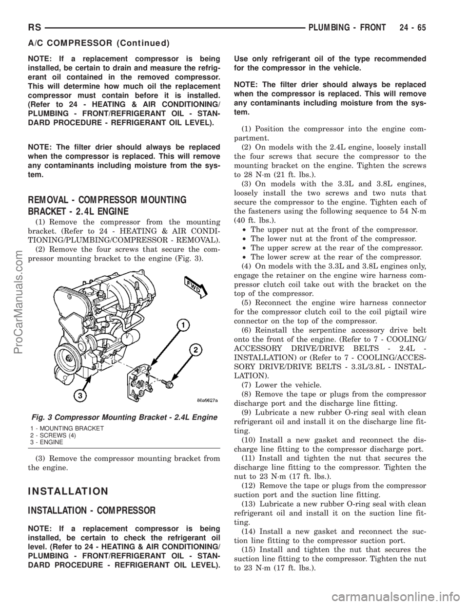
(2) Remove the four screws that secure the com-
pressor mounting bracket to the engine (Fig. 3).
(3) Remove the compressor mounting bracket from
the engine.
INSTALLATION
INSTALLATION - COMPRESSOR
NOTE: If a replacement compressor is being
installed, be certain to check the refrigerant oil
level. (Refer to 24 - HEATING & AIR CONDITIONING/
PLUMBING - FRONT/REFRIGERANT OIL - STAN-
DARD PROCEDURE - REFRIGERANT OIL LEVEL).Use only refrigerant oil of the type recommended
for the compressor in the vehicle.
NOTE: The filter drier should always be replaced
when the compressor is replaced. This will remove
any contaminants including moisture from the sys-
tem.
(1) Position the compressor into the engine com-
partment.
(2) On models with the 2.4L engine, loosely install
the four screws that secure the compressor to the
mounting bracket on the engine. Tighten the screws
to 28 N´m (21 ft. lbs.).
(3) On models with the 3.3L and 3.8L engines,
loosely install the two screws and two nuts that
secure the compressor to the engine. Tighten each of
the fasteners using the following sequence to 54 N´m
(40 ft. lbs.).
²The upper nut at the front of the compressor.
²The lower nut at the front of the compressor.
²The upper screw at the rear of the compressor.
²The lower screw at the rear of the compressor.
(4) On models with the 3.3L and 3.8L engines only,
engage the retainer on the engine wire harness com-
pressor clutch coil take out with the bracket on the
top of the compressor.
(5) Reconnect the engine wire harness connector
for the compressor clutch coil to the coil pigtail wire
connector on the top of the compressor.
(6) Reinstall the serpentine accessory drive belt
onto the front of the engine. (Refer to 7 - COOLING/
ACCESSORY DRIVE/DRIVE BELTS - 2.4L -
INSTALLATION) or (Refer to 7 - COOLING/ACCES-
SORY DRIVE/DRIVE BELTS - 3.3L/3.8L - INSTAL-
LATION).
(7) Lower the vehicle.
(8) Remove the tape or plugs from the compressor
discharge port and the discharge line fitting.
(9) Lubricate a new rubber O-ring seal with clean
refrigerant oil and install it on the discharge line fit-
ting.
(10) Install a new gasket and reconnect the dis-
charge line fitting to the compressor discharge port.
(11) Install and tighten the nut that secures the
discharge line fitting to the compressor. Tighten the
nut to 23 N´m (17 ft. lbs.).
(12) Remove the tape or plugs from the compressor
suction port and the suction line fitting.
(13) Lubricate a new rubber O-ring seal with clean
refrigerant oil and install it on the suction line fit-
ting.
(14) Install a new gasket and reconnect the suc-
tion line fitting to the compressor suction port.
(15) Install and tighten the nut that secures the
suction line fitting to the compressor. Tighten the nut
to 23 N´m (17 ft. lbs.).
Fig. 3 Compressor Mounting Bracket - 2.4L Engine
1 - MOUNTING BRACKET
2 - SCREWS (4)
3 - ENGINE
RSPLUMBING - FRONT24-65
A/C COMPRESSOR (Continued)
ProCarManuals.com
Page 2069 of 2177
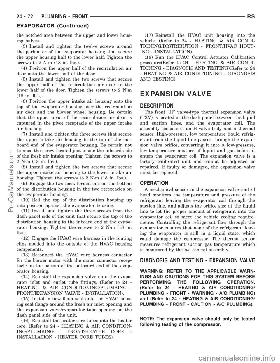
the notched area between the upper and lower hous-
ing halves.
(3) Install and tighten the twelve screws around
the perimeter of the evaporator housing that secure
the upper housing half to the lower half. Tighten the
screws to 2 N´m (18 in. lbs.).
(4) Position the upper half of the recirculation air
door onto the lower half of the door.
(5) Install and tighten the two screws that secure
the upper half of the recirculation air door to the
lower half of the door. Tighten the screws to 2 N´m
(18 in. lbs.).
(6) Position the upper intake air housing onto the
top of the evaporator housing over the recirculation
air door and the blower wheel housing. Be certain
that the upper pivot of the recirculation air door is
captured in the pivot receptacle of the upper intake
air housing.
(7) Install and tighten the three screws that secure
the upper intake air housing to the top of the out-
board end of the evaporator housing. Be certain not
to miss the screw located just inside the inboard side
of the fresh air intake opening. Tighten the screws to
2 N´m (18 in. lbs.).
(8) Install and tighten the two screws that secure
the upper intake air housing to the lower intake air
housing. Tighten the screws to 2 N´m (18 in. lbs.).
(9) Engage the two hook formations on the bottom
of the distribution housing in the two receptacles on
the evaporator housing.
(10) Roll the top of the distribution housing up
into position against the evaporator housing.
(11) Install and tighten the three screws from the
dash panel side of the unit that secure the top of the
distribution housing to the inboard end of the evapo-
rator housing. Tighten the screws to 2 N´m (18 in.
lbs.).
(12) Engage the HVAC wire harness in the routing
clips molded into the outside of the HVAC housing
components.
(13) Reconnect the HVAC wire harness connector
for the blower motor with the motor connector recep-
tacle on the bottom of the outboard end of the evap-
orator housing.
(14) Reinstall the expansion valve onto the evapo-
rator inlet and outlet tube fittings. (Refer to 24 -
HEATING & AIR CONDITIONING/PLUMBING -
FRONT/EXPANSION VALVE - INSTALLATION).
(15) Install a new foam seal onto the HVAC hous-
ing seal flange around the fresh air inlet opening and
the expansion valve/evaporator tube opening on the
dash panel side of the unit.
(16) Reinstall the heater core tubes into the heater
core. (Refer to 24 - HEATING & AIR CONDITION-
ING/PLUMBING - FRONT/HEATER CORE -
INSTALLATION - HEATER CORE TUBES).(17) Reinstall the HVAC unit housing into the
vehicle. (Refer to 24 - HEATING & AIR CONDI-
TIONING/DISTRIBUTION - FRONT/HVAC HOUS-
ING - INSTALLATION).
(18) Run the HVAC Control Actuator Calibration
procedure(Refer to 24 - HEATING & AIR CONDI-
TIONING - DIAGNOSIS AND TESTING)(Refer to 24
- HEATING & AIR CONDITIONING - DIAGNOSIS
AND TESTING).
EXPANSION VALVE
DESCRIPTION
The front ªHº valve-type thermal expansion valve
(TXV) is located at the dash panel between the liquid
and suction lines, and the evaporator coil. The
assembly consists of an H-valve body and a thermal
sensor. High-pressure, low temperature liquid refrig-
erant from the liquid line passes through the expan-
sion valve orifice, converting it into a low-pressure,
low-temperature mixture of liquid and gas before it
enters the evaporator coil. The expansion valve is a
factory calibrated unit and cannot be adjusted or
repaired. If faulty or damaged, the expansion valve
must be replaced.
OPERATION
A mechanical sensor in the expansion valve control
head monitors the temperature and pressure of the
refrigerant leaving the evaporator coil through the
suction line, and adjusts the orifice size at the liquid
line to let the proper amount of refrigerant into the
evaporator coil to meet the vehicle cooling require-
ments. Controlling the refrigerant flow through the
evaporator ensures that none of the refrigerant leav-
ing the evaporator is still in a liquid state, which
could damage the compressor. The thermo sensor
measures refrigerant suction gas temperature which
is monitored by the a/c control assembly.
DIAGNOSIS AND TESTING - EXPANSION VALVE
WARNING: REFER TO THE APPLICABLE WARN-
INGS AND CAUTIONS FOR THIS SYSTEM BEFORE
PERFORMING THE FOLLOWING OPERATION.
(Refer to 24 - HEATING & AIR CONDITIONING/
PLUMBING - FRONT - WARNING - A/C PLUMBING)
and (Refer to 24 - HEATING & AIR CONDITIONING/
PLUMBING - FRONT - CAUTION - A/C PLUMBING).
NOTE: The expansion valve should only be tested
following testing of the compressor.
24 - 72 PLUMBING - FRONTRS
EVAPORATOR (Continued)
ProCarManuals.com
Page 2082 of 2177
(6) Install and tighten the screw that secures the
liquid line fitting to the filter-drier. Tighten the screw
to 11 N´m (100 in. lbs.).
(7) Remove the tape or plugs from the liquid line
front section fitting for the filter-drier and the filter-
drier inlet port.
(8) Lubricate a new rubber O-ring seal with clean
refrigerant oil and install it on the liquid line fitting.
(9) Reconnect the liquid line fitting to the filter-
drier inlet port on the top of the filter-drier.
(10) Install and tighten the screw that secures the
liquid line fitting to the filter-drier. Tighten the screw
to 11 N´m (100 in. lbs.).
(11) Reinstall the air cleaner housing into the
right side of the engine compartment.
(12) Evacuate the refrigerant system. (Refer to 24
- HEATING & AIR CONDITIONING/PLUMBING -
FRONT/REFRIGERANT - STANDARD PROCE-
DURE - REFRIGERANT SYSTEM EVACUATE).
(13) Charge the refrigerant system. (Refer to 24 -
HEATING & AIR CONDITIONING/PLUMBING -
FRONT/REFRIGERANT - STANDARD PROCE-
DURE - REFRIGERANT SYSTEM CHARGE).
REFRIGERANT
DESCRIPTION
The refrigerant used in this air conditioning sys-
tem is a HydroFluoroCarbon (HFC), type R-134a.
Unlike R-12, which is a ChloroFluoroCarbon (CFC),
R-134a refrigerant does not contain ozone-depleting
chlorine. R-134a refrigerant is a non-toxic, non-flam-
mable, clear, and colorless liquefied gas. Even though
R-134a does not contain chlorine, it must be
reclaimed and recycled just like CFC-type refriger-
ants. This is because R-134a is a greenhouse gas and
can contribute to global warming.
OPERATION
R-134a refrigerant is not compatible with R-12
refrigerant in an air conditioning system. Even a
small amount of R-12 added to an R-134a refrigerant
system will cause compressor failure, refrigerant oil
sludge or poor air conditioning system performance.
In addition, the PolyAlkylene Glycol (PAG) synthetic
refrigerant oils used in an R-134a refrigerant system
are not compatible with the mineral-based refriger-
ant oils used in an R-12 refrigerant system. R-134a
refrigerant system service ports, service tool couplers
and refrigerant dispensing bottles have all been
designed with unique fittings to ensure that an
R-134a system is not accidentally contaminated with
the wrong refrigerant (R-12). There are also labels
posted in the engine compartment of the vehicle and
on the compressor identifying to service techniciansthat the air conditioning system is equipped with
R-134a.
DIAGNOSIS AND TESTING
DIAGNOSIS AND TESTING - REFRIGERANT
SYSTEM CHARGE LEVEL
WARNING: REFER TO THE APPLICABLE WARN-
INGS AND CAUTIONS FOR THIS SYSTEM BEFORE
PERFORMING THE FOLLOWING OPERATION.
(Refer to 24 - HEATING & AIR CONDITIONING/
PLUMBING - FRONT - WARNING - A/C PLUMBING)
and (Refer to 24 - HEATING & AIR CONDITIONING/
PLUMBING - FRONT - CAUTION - A/C PLUMBING).
NOTE: The proper amount of R-134a refrigerant for
the refrigerant system in this model is:
²Single or Dual Zone (Front Unit Only) - 0.96
kilograms (2.13 pounds or 34 ounces)
²Three Zone (Front and Rear Units) - 1.31 kilo-
grams (2.88 pounds or 46 ounces)
The procedure that follows should be used to deter-
mine whether the refrigerant system contains the
proper refrigerant charge. Symptoms of an improper
refrigerant charge (low) include: poor air conditioner
performance, fog emitted from the air conditioner
outlets, a hissing sound from the expansion valve/
evaporator area. There are two different methods
with which the refrigerant charge level may be
tested:
1. Using a DRBIIItscan tool, a thermocouple and
the Charge Determination Chart (Fig. 31). Refer to
the appropriate diagnostic information.
2. Using a manifold gauge set, a thermocouple and
the Charge Determination Chart (Fig. 31).
A temperature probe is required to measure liquid
line temperature. The clamp-on, Type K thermocou-
ple temperature probe used in this procedure is
available through the DaimlerChrysler Professional
Service Equipment (PSE) program. This probe (PSE
#66-324-0014 or #80PK-1A) is compatible with tem-
perature-measuring instruments that accept Type K
thermocouples, and have a miniature connector
input. Other temperature probes are available
through aftermarket sources; however, all references
in this procedure will reflect the use of the probe
made available through the PSE program.
In order to use the temperature probe, a digital
thermometer will also be required. If a digital ther-
mometer is not available, an adapter is available
through the PSE program that will convert any stan-
dard digital multimeter into a digital thermometer.
This adapter is designed to accept any standard Type
RSPLUMBING - FRONT24-85
RECEIVER/DRIER (Continued)
ProCarManuals.com
Page 2093 of 2177
(6) Remove the nut that secures the expansion
valve bracket to the expansion valve stud.
(7) Remove the expansion valve bracket from the
expansion valve stud.
(8) Remove the nut that secures the evaporator
line extension seal plate to the expansion valve stud.
(9) Remove the evaporator line extension seal
plate from the expansion valve stud.
(10) Remove the evaporator line extension from
the expansion valve and the rear heater-A/C housing
base.
(11) Remove the seals from the evaporator line
extension fittings and discard.
(12) Install plugs in, or tape over the opened evap-
orator line extension fittings and both expansion
valve ports.
INSTALLATION
INSTALLATION - REAR EVAPORATOR
NOTE: If the evaporator is being replaced, add 60
milliliters (2 fluid ounces) of refrigerant oil to the
refrigerant system. Use only refrigerant oil of the
type recommended for the compressor in the vehi-
cle.
(1) Carefully lower the evaporator and its foam
wrap into the lower half of the rear heater-A/C hous-
ing.
(2) Position the upper half of the rear heater-A/C
housing onto the lower half.
(3) Install the three small metal spring clips that
secure the upper half of the rear heater-A/C housing
to the lower half.
(4) Install and tighten the three screws that secure
the upper half of the rear heater-A/C housing to the
lower half. Tighten the screws to 2 N´m (18 in. lbs.).
(5) Install the rubber grommet that seals the evap-
orator inlet and outlet tubes to the rear heater-A/C
housing near the expansion valve.
(6) Reinstall the rear expansion valve onto the
rear evaporator. (Refer to 24 - HEATING & AIR
CONDITIONING/PLUMBING - REAR/EXPANSION
VALVE - INSTALLATION).
(7) Reinstall the rear evaporator extension line
onto the expansion valve. (Refer to 24 - HEATING &
AIR CONDITIONING/PLUMBING - REAR/EVAPO-
RATOR - INSTALLATION - EVAPORATOR EXTEN-
SION LINE).
(8) Reinstall the rear heater-A/C unit housing into
the vehicle. (Refer to 24 - HEATING & AIR CONDI-
TIONING/DISTRIBUTION - REAR/REAR HEATER-
A/C HOUSING - INSTALLATION).
INSTALLATION - EVAPORATOR LINE
EXTENSION
(1) Remove the tape or plugs from the evaporator
line extension fittings and both expansion valve
ports.
(2) Lubricate new rubber O-ring seals with clean
refrigerant oil and install them on the evaporator
line extension fittings.
(3) Position the evaporator line extension to the
expansion valve and the rear heater-A/C housing
base.
(4) Position the evaporator line extension seal
plate over the expansion valve stud.
(5) Install and tighten the nut that secures the
evaporator line extension seal plate to the expansion
valve stud. Tighten the nut to 23 N´m (17 ft. lbs.).
(6) Position the expansion valve bracket over the
expansion valve stud.
(7) Install and tighten the two screws that secure
the expansion valve bracket to the lower rear heater-
A/C unit housing. Tighten the screws to 2 N´m (18 in.
lbs.).
(8) Install and tighten the nut that secures the
expansion valve bracket to the expansion valve stud.
Tighten the nut to 23 N´m (17 ft. lbs.).
(9) Carefully restore the expansion valve foam
insulator wrap back around the expansion valve.
(10) Position the plate that captures and seals the
evaporator line extension onto the rear heater-A/C
unit housing base.
(11) Install and tighten the screw that secures the
capture plate to the base of the rear heater-A/C unit
housing. Tighten the screw to 2 N´m (18 in. lbs.).
(12) Reinstall the rear heater-A/C unit housing
into the vehicle. (Refer to 24 - HEATING & AIR
CONDITIONING/DISTRIBUTION - REAR/REAR
HEATER-A/C HOUSING - INSTALLATION).
EXPANSION VALVE
DESCRIPTION
The rear ªHº valve-type thermal expansion valve
(TXV) is located at the rear of the rear heater-A/C
unit housing between the evaporator line extension
and the evaporator coil. High-pressure, low tempera-
ture liquid refrigerant from the liquid line passes
through the expansion valve orifice, converting it into
a low-pressure, low-temperature mixture of liquid
and gas before it enters the evaporator coil. The
expansion valve is a factory calibrated unit and can-
not be adjusted or repaired. If faulty or damaged, the
expansion valve must be replaced.
24 - 96 PLUMBING - REARRS
EVAPORATOR (Continued)
ProCarManuals.com