2003 CHRYSLER CARAVAN battery replacement
[x] Cancel search: battery replacementPage 523 of 2177

RESTRAINTS
DESCRIPTION
This vehicle is equipped with a Frontal Impact Air-
bag System, which utilizes the driver/passenger air-
bags and seatbelt pretensioners. This system is
designed to protect occupants in the event of a front
impact collision. These airbags and seatbelt preten-
sioners are all serviceable parts. If these pyrotechnics
are deployed or defective, they must be replaced, as
well as the Occupant Restraint Controller (ORC)
must be diagnosed following procedures outlined in
the service/diagnostic manuals.
Vehicles equipped with the Side Impact Airbag
System, the seat back assembly must be replaced, as
well as the Side Impact Airbag Control Module
(SIACM) must be diagnosed following procedures
outlined in the service/diagnostic manuals.
OPERATION
The Occupant Restraint Controller (ORC) controls
the driver/passenger airbags and seat belt tensioners.
If the ORC determines that the impact is severe
enough, the driver/passenger/side airbags and seat
belt tensioners will deploy. Once a deployment
occurs, these devices, and all damaged parts must be
replaced, as well as the ORC must be diagnosed fol-
lowing procedures outlined in the service/diagnostic
manuals.
The Side Impact Airbag Control Module (SIACM),
the seat back assemblies and all damaged parts must
be replaced, as well as the SIACM must be diagnosed
following procedures outlined in the service/diagnos-
tic manuals.
WARNING
WARNING: THIS SYSTEM IS A SENSITIVE, COM-
PLEX ELECTRO±MECHANICAL UNIT. DISCONNECT
AND ISOLATE THE BATTERY NEGATIVE CABLE
BEFORE BEGINNING AIRBAG SYSTEM COMPO-
NENT REMOVAL OR INSTALLATION PROCEDURES.
THIS WILL DISABLE THE AIRBAG SYSTEM. FAIL-
URE TO DISCONNECT THE BATTERY COULD
RESULT IN ACCIDENTAL AIRBAG DEPLOYMENT
AND POSSIBLE PERSONAL INJURY.
ALLOW SYSTEM CAPACITOR TO DISCHARGE FOR
TWO MINUTES BEFORE REMOVING AIRBAG COM-
PONENTS.
DO NOT PLACE AN INTACT UNDEPLOYED AIRBAG
FACE DOWN ON A SOLID SURFACE, THE AIRBAG
WILL PROPEL INTO THE AIR IF ACCIDENTALLY
DEPLOYED AND COULD RESULT IN PERSONAL
INJURY. WHEN CARRYING OR HANDLING AN
UNDEPLOYED AIRBAG MODULE, THE TRIM SIDE
OF THE AIRBAG SHOULD BE POINTING AWAYFROM THE BODY TO MINIMIZE POSSIBILITY OF
INJURY IF ACCIDENTAL DEPLOYMENT OCCURS.
REPLACE AIRBAG SYSTEM COMPONENTS WITH
MOPARTREPLACEMENT PARTS. SUBSTITUTE
PARTS MAY APPEAR INTERCHANGEABLE, BUT
INTERNAL DIFFERENCES MAY RESULT IN INFE-
RIOR OCCUPANT PROTECTION.
WEAR SAFETY GLASSES, RUBBER GLOVES, AND
LONG SLEEVED CLOTHING WHEN CLEANING
POWDER RESIDUE FROM VEHICLE AFTER AIRBAG
DEPLOYMENT. SODIUM HYDROXIDE POWDER
RESIDUE EMITTED FROM A DEPLOYED AIRBAG
CAN CAUSE SKIN IRRITATION. FLUSH AFFECTED
AREA WITH COOL WATER IF IRRITATION IS EXPE-
RIENCED. IF NASAL OR THROAT IRRITATION IS
EXPERIENCED, EXIT THE VEHICLE FOR FRESH AIR
UNTIL THE IRRITATION CEASES. IF IRRITATION
CONTINUES, SEE A PHYSICIAN.
DO NOT USE A REPLACEMENT AIRBAG THAT IS
NOT IN THE ORIGINAL PACKAGING, IMPROPER
DEPLOYMENT AND PERSONAL INJURY CAN
RESULT.
THE FACTORY INSTALLED FASTENERS, SCREWS
AND BOLTS USED TO FASTEN AIRBAG COMPO-
NENTS HAVE A SPECIAL COATING AND ARE SPE-
CIFICALLY DESIGNED FOR THE AIRBAG SYSTEM.
DO NOT USE SUBSTITUTE FASTENERS, USE ONLY
ORIGINAL EQUIPMENT FASTENERS LISTED IN THE
PARTS CATALOG WHEN FASTENER REPLACE-
MENT IS REQUIRED.
CAUTION:
Deployed and Nondeployed Air Bags may or may
not have live pyrotechnic material within the air bag
inflator. Do not dispose of Driver and Passenger
Airbags unless you are sure of complete deploy-
ment. Please refer to the Hazardous Substance
Control System for Proper Disposal. Dispose of
deployed air bags in a manner consistent with
state, provincial, local, and federal regulations.
DIAGNOSIS AND TESTING - AIRBAG SYSTEM
(1) With the battery negative remote cable discon-
nected, connect the DRB IIItscan tool to the Data
Link connector.
(2) Turn the ignition key to the ON position. Exit
vehicle with the scan tool.
(3) After checking that no one is inside the vehicle,
connect the battery negative remote terminal.
(4) Read and record theACTIVEDiagnostic Trou-
ble Code (DTC) data.
(5) Read and record anySTOREDDTC's.
(6) Refer to the proper Body Diagnostic Procedures
manual if any DTC's are found in Step 4 and Step 5.
(7) If the airbag warning lamp either fails to light,
or goes ON and stays ON, there is a system malfunc-
8O - 2 RESTRAINTSRS
ProCarManuals.com
Page 544 of 2177

REMOVAL
(1) Release hood latch and open hood.
(2) Disconnect the negative battery cable.
(3) Disconnect the throttle and speed control cable
ends from throttle body (Fig. 2).
(4) Depress lock tabs holding speed control and
throttle cable casing to cable mount bracket.
(5) Disconnect vacuum line from speed control
servo that leads to the battery tray/vacuum reservoir.
(6) Remove battery tray/vacuum reservoir, refer to
the Battery section for more information (Fig. 3).(7) Remove speed control servo and bracket (Fig.
4).
(8) Disconnect wire connector from speed control
servo.
(9) Remove speed control servo.
INSTALLATION
Transfer speed control cable to replacement speed
control servo.
(1) Install retaining clip to cable at servo.
(2) Install 2 nuts at cable to servo and servo
bracket, tighten to 7 N´m (60 ins. lbs.).
(3) Connect electrical connector to servo.
(4) Connect vacuum line to speed control servo
that leads to the battery tray/vacuum reservoir.
(5) Install speed control servo and bracket.
(6) Install battery tray/vacuum reservoir, refer to
the Battery section for more information.
(7) Install speed control and throttle cable casing
to cable mount bracket.
(8) Connect the throttle and speed control cable
ends to throttle body.
(9) Connect the negative battery cable.
Fig. 2 Speed Control Cable End
1 - SPEED CONTROL VACUUM HOSE
2 - THROTTLE BODY
3 - SPEED CONTROL CABLE
Fig. 3 BATTERY TRAY/VACUUM RESERVOIR
Fig. 4 SPEED CONTROL SERVO
RSSPEED CONTROL8P-5
SERVO (Continued)
ProCarManuals.com
Page 1287 of 2177
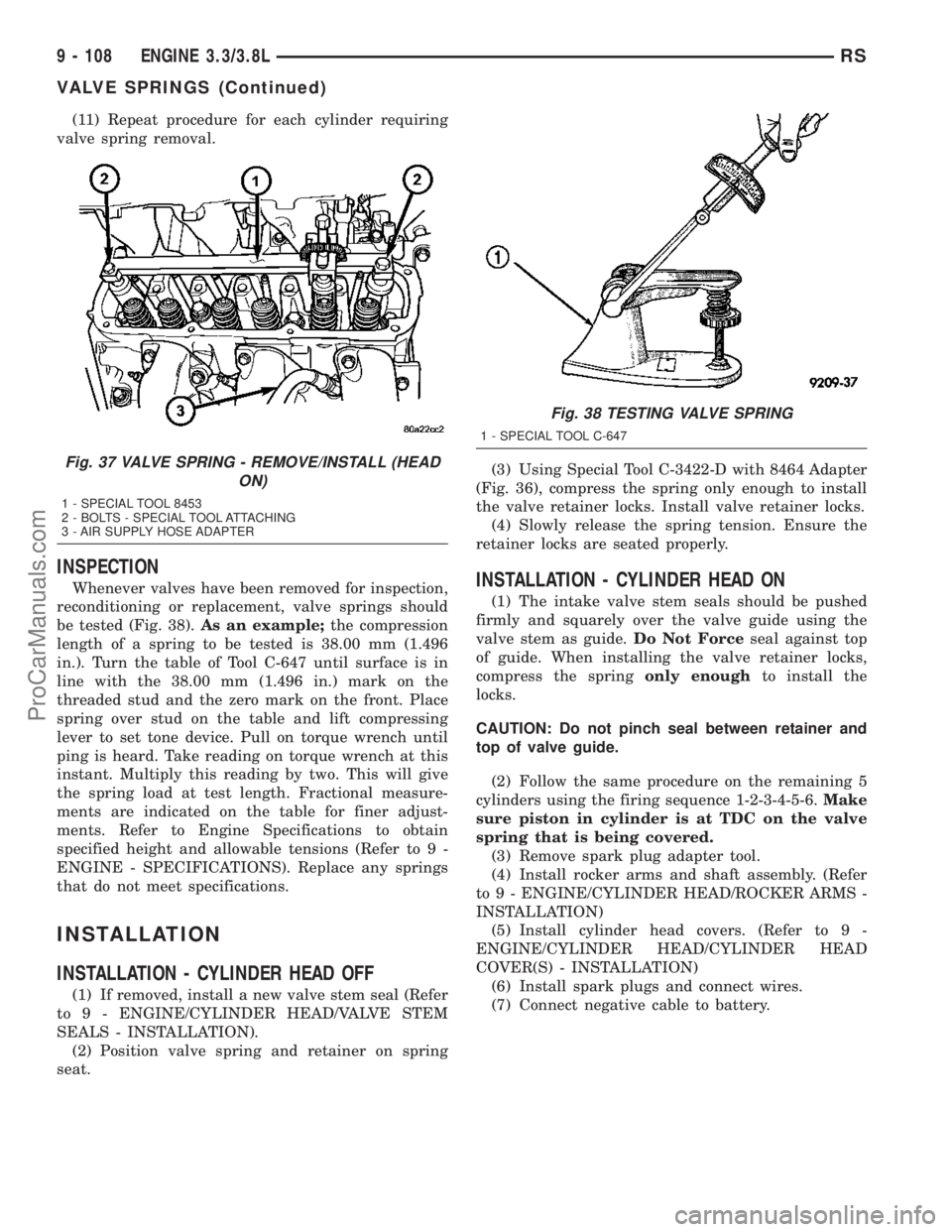
(11) Repeat procedure for each cylinder requiring
valve spring removal.
INSPECTION
Whenever valves have been removed for inspection,
reconditioning or replacement, valve springs should
be tested (Fig. 38).As an example;the compression
length of a spring to be tested is 38.00 mm (1.496
in.). Turn the table of Tool C-647 until surface is in
line with the 38.00 mm (1.496 in.) mark on the
threaded stud and the zero mark on the front. Place
spring over stud on the table and lift compressing
lever to set tone device. Pull on torque wrench until
ping is heard. Take reading on torque wrench at this
instant. Multiply this reading by two. This will give
the spring load at test length. Fractional measure-
ments are indicated on the table for finer adjust-
ments. Refer to Engine Specifications to obtain
specified height and allowable tensions (Refer to 9 -
ENGINE - SPECIFICATIONS). Replace any springs
that do not meet specifications.
INSTALLATION
INSTALLATION - CYLINDER HEAD OFF
(1) If removed, install a new valve stem seal (Refer
to 9 - ENGINE/CYLINDER HEAD/VALVE STEM
SEALS - INSTALLATION).
(2) Position valve spring and retainer on spring
seat.(3) Using Special Tool C-3422-D with 8464 Adapter
(Fig. 36), compress the spring only enough to install
the valve retainer locks. Install valve retainer locks.
(4) Slowly release the spring tension. Ensure the
retainer locks are seated properly.
INSTALLATION - CYLINDER HEAD ON
(1) The intake valve stem seals should be pushed
firmly and squarely over the valve guide using the
valve stem as guide.Do Not Forceseal against top
of guide. When installing the valve retainer locks,
compress the springonly enoughto install the
locks.
CAUTION: Do not pinch seal between retainer and
top of valve guide.
(2) Follow the same procedure on the remaining 5
cylinders using the firing sequence 1-2-3-4-5-6.Make
sure piston in cylinder is at TDC on the valve
spring that is being covered.
(3) Remove spark plug adapter tool.
(4) Install rocker arms and shaft assembly. (Refer
to 9 - ENGINE/CYLINDER HEAD/ROCKER ARMS -
INSTALLATION)
(5) Install cylinder head covers. (Refer to 9 -
ENGINE/CYLINDER HEAD/CYLINDER HEAD
COVER(S) - INSTALLATION)
(6) Install spark plugs and connect wires.
(7) Connect negative cable to battery.
Fig. 37 VALVE SPRING - REMOVE/INSTALL (HEAD
ON)
1 - SPECIAL TOOL 8453
2 - BOLTS - SPECIAL TOOL ATTACHING
3 - AIR SUPPLY HOSE ADAPTER
Fig. 38 TESTING VALVE SPRING
1 - SPECIAL TOOL C-647
9 - 108 ENGINE 3.3/3.8LRS
VALVE SPRINGS (Continued)
ProCarManuals.com
Page 1356 of 2177

FRONT CRADLE
CROSSMEMBER
DESCRIPTION
DESCRIPTION - FRONT CRADLE
CROSSMEMBER
This vehicle uses a one piece cast aluminum cradle
for the front cradle crossmember. The cradle cross-
member is used as the attaching points for the lower
control arms, stabilizer bar and steering gear. The
cradle also has the power steering hoses and the
chassis brake tubes attached to it.
WARNING: If a threaded hole in the suspension cra-
dle needs to be repaired, only use the type of
thread insert and installation procedure specified
for this application.
The threaded holes in the front cradle crossmem-
ber that are used for attachment of the lower control
arm rear bushing retainer, power steering hose and
chassis brake tubes can be repaired. The repair is
done by the installation of a Heli-Coiltthread insert
which has been specifically developed for this appli-
cation. Refer to the Mopar Parts Catalog for the spec-
ified Heli-Coiltthread insert to be used for this
application. The procedure for installing the Heli-
Coiltthread insert is detailed in the Service Proce-
dures section in this group of the service manual.
DESCRIPTION - FRONT CRADLE
CROSSMEMBER THREAD REPAIR
WARNING: When performing this procedure use
only the thread inserts which are specified in the
Mopar Parts Catalog for this repair procedure.
These thread inserts have been specifically devel-
oped for this application and use of other types of
thread inserts can result in an inferior long term
repair.
The threaded holes in the front cradle crossmem-
ber, if damaged, can repaired by installing a Heli-
Coiltthread insert.
The threaded holes that are repairable using the
thread insert, are the lower control arm rear bushing
retainer mounting bolt holes, routing bracket attach-
ing locations for the power steering hoses, and brake
hose attachment holes.
This repair procedure now allows the threaded
holes in the cradle crossmember to be repaired, elim-
inating the need to replace the cradle crossmember if
damage occurs to one of the threaded holes.The thread inserts for this application are specified
by part number in the Mopar Parts Catalog.Do not
use a substitute thread insert.
The specific tools and equipment required to install
the thread insert are listed below. Refer to the
instructions included with the thread insert for the
detailed procedure used for the installation of the
thread insert.
NOTE: The thread inserts for this application are for
the repair of M8x1.25 and M10x1.5 threads. Be sure
the correct tools are used for the required thread
insert size.
TOOL REQUIREMENT FOR M8x1.25 Thread
²8.3mm (5/16 in.) Drill Bit
²120É Countersink
²Heli-CoiltTap #4863-8
²Heli-CoiltGage #4624-8
²Heli-CoiltHand Inserting Tool 7751-8
²Needle Nose Pliers ± For Removal Of Thread
Insert Driving Tang
TOOL REQUIREMENT FOR M10x1.5 Thread
²10.5mm (25/64 in.) Drill Bit
²120É Countersink
²Heli-CoiltTap #4863-10
²Heli-CoiltGage #4624-10
²Heli-CoiltHand Inserting Tool 7751-10
²Needle Nose Pliers ± For Removal Of Thread
Insert Driving Tang
REMOVAL
The front cradle crossmember must be installed in
the design location to achieve proper front end sus-
pension alignment. If the cradle crossmember is
removed without applying reference marks on the
frame rails, align the cradle crossmember according
to the dimensions provided in this group.
NOTE: If the caged nuts in the frame rails become
damaged and cannot be reused, a replacement nut
can be obtained through MoparT.
REMOVAL
(1) Disconnect battery negative cable.
(2) Remove steering column lower cover from
instrument panel (Refer to 23 - BODY/INSTRU-
MENT PANEL/STEERING COLUMN OPENING
COVER - REMOVAL).
(3) Remove steering column cover backing plate
(Refer to 23 - BODY/INSTRUMENT PANEL/STEER-
ING COLUMN COVER BACKING PLATE - REMOV-
AL).
RSFRAME & BUMPERS13-9
ProCarManuals.com
Page 1358 of 2177
INSTALLATION
NOTE: If cradle crossmember requires replacement.
Refer to Group 2, Suspension, to transfer suspen-
sion components and Group 19, Steering, to trans-
fer steering components.
(1) Support crossmember on suitable lifting device
(Fig. 14).
(2) Position crossmember to vehicle.
(3) Loosely install bolts attaching cradle cross-
member to front frame rails.
(4) Align crossmember to previously made marks
on frame rails.
(5) Tighten bolts attaching cradle crossmember to
frame rails.
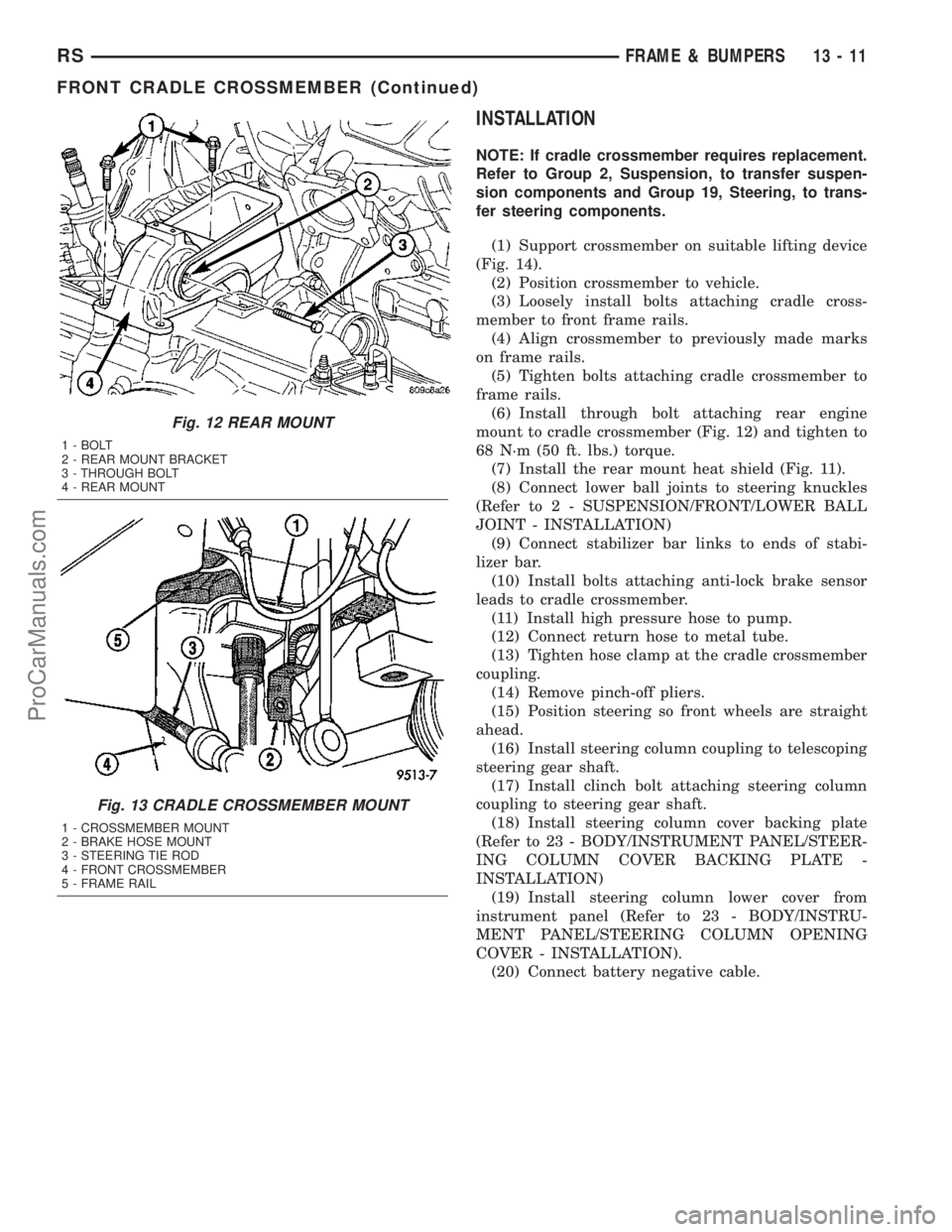
(6) Install through bolt attaching rear engine
mount to cradle crossmember (Fig. 12) and tighten to
68 N´m (50 ft. lbs.) torque.
(7) Install the rear mount heat shield (Fig. 11).
(8) Connect lower ball joints to steering knuckles
(Refer to 2 - SUSPENSION/FRONT/LOWER BALL
JOINT - INSTALLATION)
(9) Connect stabilizer bar links to ends of stabi-
lizer bar.
(10) Install bolts attaching anti-lock brake sensor
leads to cradle crossmember.
(11) Install high pressure hose to pump.
(12) Connect return hose to metal tube.
(13) Tighten hose clamp at the cradle crossmember
coupling.
(14) Remove pinch-off pliers.
(15) Position steering so front wheels are straight
ahead.
(16) Install steering column coupling to telescoping
steering gear shaft.
(17) Install clinch bolt attaching steering column
coupling to steering gear shaft.
(18) Install steering column cover backing plate
(Refer to 23 - BODY/INSTRUMENT PANEL/STEER-
ING COLUMN COVER BACKING PLATE -
INSTALLATION)
(19) Install steering column lower cover from
instrument panel (Refer to 23 - BODY/INSTRU-
MENT PANEL/STEERING COLUMN OPENING
COVER - INSTALLATION).
(20) Connect battery negative cable.
Fig. 12 REAR MOUNT
1 - BOLT
2 - REAR MOUNT BRACKET
3 - THROUGH BOLT
4 - REAR MOUNT
Fig. 13 CRADLE CROSSMEMBER MOUNT
1 - CROSSMEMBER MOUNT
2 - BRAKE HOSE MOUNT
3 - STEERING TIE ROD
4 - FRONT CROSSMEMBER
5 - FRAME RAIL
RSFRAME & BUMPERS13-11
FRONT CRADLE CROSSMEMBER (Continued)
ProCarManuals.com
Page 1361 of 2177
FUEL DELIVERY
DESCRIPTION
DESCRIPTION
The front wheel drive car uses a plastic fuel tank
located rear center of the vehicle.
The Fuel Delivery System consists of: the following
items:
²Electric fuel pump module
²Fuel filter
²Tubes/lines/hoses
²Fuel injectors
The in-tank fuel pump module contains the fuel
pump. The pump is serviced as part of the fuel pump
module. Refer to Fuel Pump Module.
The fuel filter is replaceable only as part of the
fuel pump module.
DESCRIPTION - FFV REPLACEMENT PARTS
Many components in a Flexible Fuel Vehicle (FFV)
are designed to be compatible with ethanol. Always
be sure that the vehicle is serviced with correct etha-
nol compatible parts.
CAUTION: Replacing fuel system components with
non-ethanol compatible components can damage
your vehicle and may void the warranty.
OPERATION
The fuel system provides fuel pressure by an
in-tank pump module. The PCM controls the opera-
tion of the fuel system by providing battery voltage
to the fuel pump through the fuel pump relay. The
PCM requires only three inputs and a good ground to
operate the fuel pump relay. The three inputs are:
²Ignition voltage
²Crankshaft Position (CKP) sensor
²Camshaft Position (CMP) sensor
DIAGNOSIS AND TESTING - FUEL DELIVERY
SYSTEM
(Refer to Appropriate Diagnostic Information)
STANDARD PROCEDURE
STANDARD PROCEDURE - FUEL SYSTEM
PRESSURE RELEASE PROCEDURE
(1) Remove Fuel Pump relay from Power Distribu-
tion Center (PDC). For location of relay, refer to label
on underside of PDC cover.
(2) Start and run engine until it stalls.(3) Attempt restarting engine until it will no
longer run.
(4) Turn ignition key to OFF position.
(5) Return fuel pump relay to PDC.
(6) One or more Diagnostic Trouble Codes (DTC's)
may have been stored in PCM memory due to fuel
pump relay removal. The DRB IIItscan tool must be
used to erase a DTC.
STANDARD PROCEDURE - DRAINING FUEL
TANK
Two different procedures may be used to drain fuel
tank (lowering tank or using DRB scan tool).
The quickest draining procedure involves lowering
the fuel tank.
WARNING: RELEASE FUEL SYSTEM PRESSURE
BEFORE SERVICING FUEL SYSTEM COMPONENTS.
SERVICE VEHICLES IN WELL VENTILATED AREAS
AND AVOID IGNITION SOURCES. NEVER SMOKE
WHILE SERVICING THE VEHICLE.
As an alternative procedure, the electric fuel pump
may be activated allowing tank to be drained at fuel
rail connection. Refer to DRBIIItscan tool for fuel
pump activation procedures. Before disconnecting
fuel line at fuel rail, release fuel pressure. Refer to
the Fuel System Pressure Release Procedure in this
group for procedures. Disconnect the fuel line at the
fuel rail and remove the plastic retainer from the
fuel rail. Take plastic retainer and install it back into
the fuel line from body. Attach end of special test
hose tool number 8978 at fuel line connection from
the body line. Position opposite end of this hose tool
to an approved gasoline draining station. Activate
fuel pump and drain tank until empty. When done
remove the special test hose tool number 8978 from
the body line. Remove the plastic retainer from the
special test hose tool number 8978 and reinstall it
into the fuel line from the body. Install the fuel line
to the fuel rail.
If electric fuel pump is not operating, tank must be
lowered for fuel draining. Refer to following proce-
dures.
(1) Remove fuel filler cap.
(2) Perform the Fuel System Pressure Release pro-
cedure.
(3) Disconnect negative cable from battery.
(4) Raise vehicle and support.
(5) Certain models are equipped with a separate
grounding wire (strap) connecting the fuel fill tube
assembly to the body. Disconnect wire by removing
screw.
(6) Open fuel fill door and remove screws mount-
ing fuel filler tube assembly to body. Do not discon-
14 - 2 FUEL DELIVERYRS
ProCarManuals.com
Page 1571 of 2177
TORQUE CONVERTER LEAKAGE
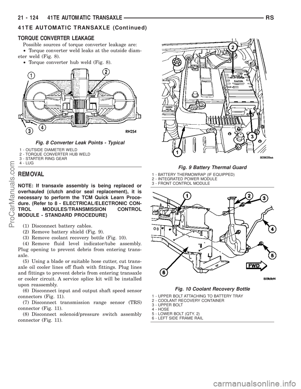
Possible sources of torque converter leakage are:
²Torque converter weld leaks at the outside diam-
eter weld (Fig. 8).
²Torque converter hub weld (Fig. 8).
REMOVAL
NOTE: If transaxle assembly is being replaced or
overhauled (clutch and/or seal replacement), it is
necessary to perform the TCM Quick Learn Proce-
dure. (Refer to 8 - ELECTRICAL/ELECTRONIC CON-
TROL MODULES/TRANSMISSION CONTROL
MODULE - STANDARD PROCEDURE)
(1) Disconnect battery cables.
(2) Remove battery shield (Fig. 9).
(3) Remove coolant recovery bottle (Fig. 10).
(4) Remove fluid level indicator/tube assembly.
Plug opening to prevent debris from entering trans-
axle.
(5) Using a blade or suitable hose cutter, cut trans-
axle oil cooler lines off flush with fittings. Plug lines
and fittings to prevent debris from entering transaxle
or cooler circuit. A service splice kit will be installed
upon reassembly.
(6) Disconnect input and output shaft speed sensor
connectors (Fig. 11).
(7) Disconnect transmission range sensor (TRS)
connector (Fig. 11).
(8) Disconnect solenoid/pressure switch assembly
connector (Fig. 11).
Fig. 8 Converter Leak Points - Typical
1 - OUTSIDE DIAMETER WELD
2 - TORQUE CONVERTER HUB WELD
3 - STARTER RING GEAR
4 - LUG
Fig. 9 Battery Thermal Guard
1 - BATTERY THERMOWRAP (IF EQUIPPED)
2 - INTEGRATED POWER MODULE
3 - FRONT CONTROL MODULE
Fig. 10 Coolant Recovery Bottle
1 - UPPER BOLT ATTACHING TO BATTERY TRAY
2 - COOLANT RECOVERY CONTAINER
3 - UPPER BOLT
4 - HOSE
5 - LOWER BOLT (QTY. 2)
6 - LEFT SIDE FRAME RAIL
21 - 124 41TE AUTOMATIC TRANSAXLERS
41TE AUTOMATIC TRANSAXLE (Continued)
ProCarManuals.com
Page 1769 of 2177
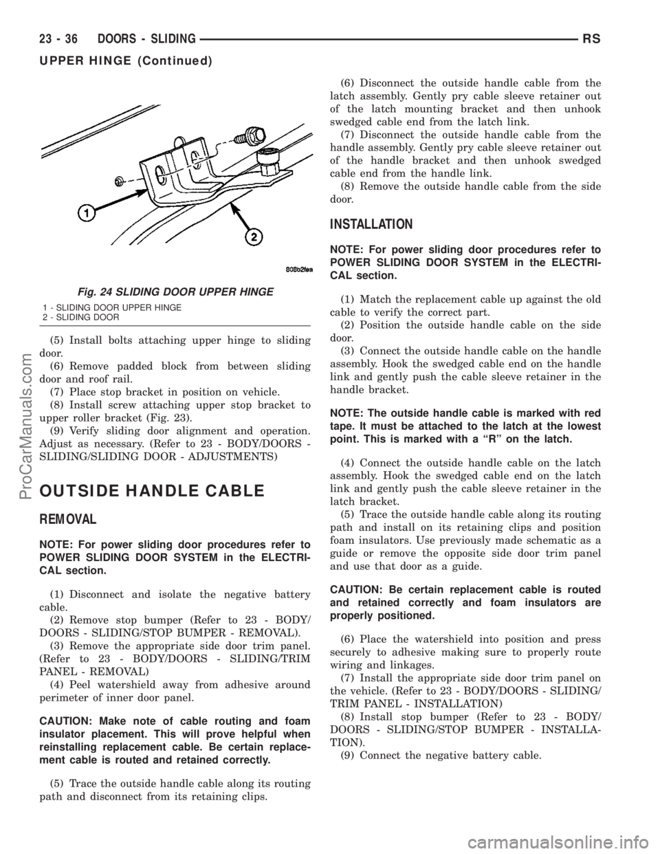
(5) Install bolts attaching upper hinge to sliding
door.
(6) Remove padded block from between sliding
door and roof rail.
(7) Place stop bracket in position on vehicle.
(8) Install screw attaching upper stop bracket to
upper roller bracket (Fig. 23).
(9) Verify sliding door alignment and operation.
Adjust as necessary. (Refer to 23 - BODY/DOORS -
SLIDING/SLIDING DOOR - ADJUSTMENTS)
OUTSIDE HANDLE CABLE
REMOVAL
NOTE: For power sliding door procedures refer to
POWER SLIDING DOOR SYSTEM in the ELECTRI-
CAL section.
(1) Disconnect and isolate the negative battery
cable.
(2) Remove stop bumper (Refer to 23 - BODY/
DOORS - SLIDING/STOP BUMPER - REMOVAL).
(3) Remove the appropriate side door trim panel.
(Refer to 23 - BODY/DOORS - SLIDING/TRIM
PANEL - REMOVAL)
(4) Peel watershield away from adhesive around
perimeter of inner door panel.
CAUTION: Make note of cable routing and foam
insulator placement. This will prove helpful when
reinstalling replacement cable. Be certain replace-
ment cable is routed and retained correctly.
(5) Trace the outside handle cable along its routing
path and disconnect from its retaining clips.(6) Disconnect the outside handle cable from the
latch assembly. Gently pry cable sleeve retainer out
of the latch mounting bracket and then unhook
swedged cable end from the latch link.
(7) Disconnect the outside handle cable from the
handle assembly. Gently pry cable sleeve retainer out
of the handle bracket and then unhook swedged
cable end from the handle link.
(8) Remove the outside handle cable from the side
door.
INSTALLATION
NOTE: For power sliding door procedures refer to
POWER SLIDING DOOR SYSTEM in the ELECTRI-
CAL section.
(1) Match the replacement cable up against the old
cable to verify the correct part.
(2) Position the outside handle cable on the side
door.
(3) Connect the outside handle cable on the handle
assembly. Hook the swedged cable end on the handle
link and gently push the cable sleeve retainer in the
handle bracket.
NOTE: The outside handle cable is marked with red
tape. It must be attached to the latch at the lowest
point. This is marked with a ªRº on the latch.
(4) Connect the outside handle cable on the latch
assembly. Hook the swedged cable end on the latch
link and gently push the cable sleeve retainer in the
latch bracket.
(5) Trace the outside handle cable along its routing
path and install on its retaining clips and position
foam insulators. Use previously made schematic as a
guide or remove the opposite side door trim panel
and use that door as a guide.
CAUTION: Be certain replacement cable is routed
and retained correctly and foam insulators are
properly positioned.
(6) Place the watershield into position and press
securely to adhesive making sure to properly route
wiring and linkages.
(7) Install the appropriate side door trim panel on
the vehicle. (Refer to 23 - BODY/DOORS - SLIDING/
TRIM PANEL - INSTALLATION)
(8) Install stop bumper (Refer to 23 - BODY/
DOORS - SLIDING/STOP BUMPER - INSTALLA-
TION).
(9) Connect the negative battery cable.
Fig. 24 SLIDING DOOR UPPER HINGE
1 - SLIDING DOOR UPPER HINGE
2 - SLIDING DOOR
23 - 36 DOORS - SLIDINGRS
UPPER HINGE (Continued)
ProCarManuals.com