2003 CHRYSLER CARAVAN battery
[x] Cancel search: batteryPage 1090 of 2177
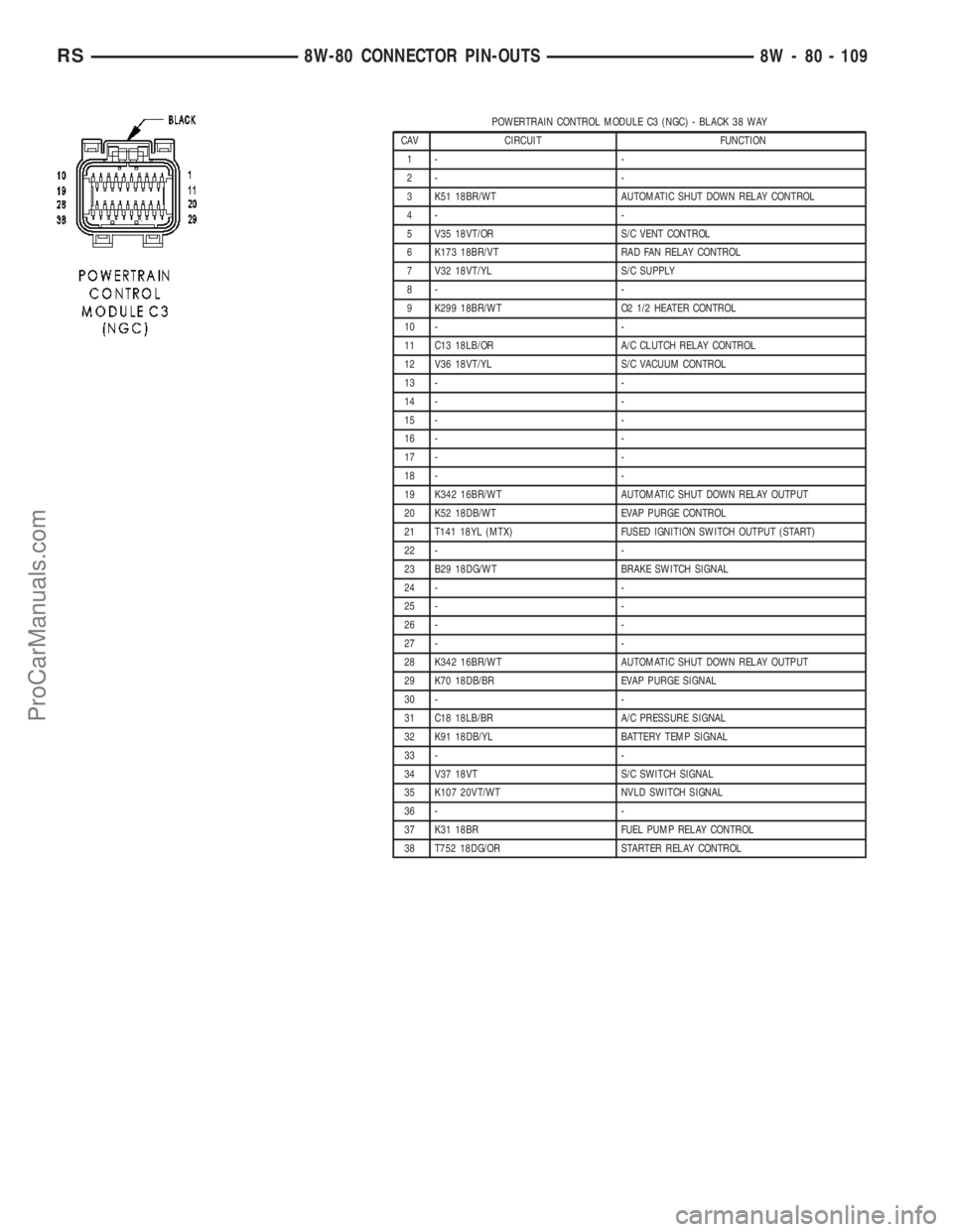
POWERTRAIN CONTROL MODULE C3 (NGC) - BLACK 38 WAY
CAV CIRCUIT FUNCTION
1- -
2- -
3 K51 18BR/WT AUTOMATIC SHUT DOWN RELAY CONTROL
4- -
5 V35 18VT/OR S/C VENT CONTROL
6 K173 18BR/VT RAD FAN RELAY CONTROL
7 V32 18VT/YL S/C SUPPLY
8- -
9 K299 18BR/WT O2 1/2 HEATER CONTROL
10 - -
11 C13 18LB/OR A/C CLUTCH RELAY CONTROL
12 V36 18VT/YL S/C VACUUM CONTROL
13 - -
14 - -
15 - -
16 - -
17 - -
18 - -
19 K342 16BR/WT AUTOMATIC SHUT DOWN RELAY OUTPUT
20 K52 18DB/WT EVAP PURGE CONTROL
21 T141 18YL (MTX) FUSED IGNITION SWITCH OUTPUT (START)
22 - -
23 B29 18DG/WT BRAKE SWITCH SIGNAL
24 - -
25 - -
26 - -
27 - -
28 K342 16BR/WT AUTOMATIC SHUT DOWN RELAY OUTPUT
29 K70 18DB/BR EVAP PURGE SIGNAL
30 - -
31 C18 18LB/BR A/C PRESSURE SIGNAL
32 K91 18DB/YL BATTERY TEMP SIGNAL
33 - -
34 V37 18VT S/C SWITCH SIGNAL
35 K107 20VT/WT NVLD SWITCH SIGNAL
36 - -
37 K31 18BR FUEL PUMP RELAY CONTROL
38 T752 18DG/OR STARTER RELAY CONTROL
RS8W-80 CONNECTOR PIN-OUTS8W - 80 - 109
ProCarManuals.com
Page 1098 of 2177
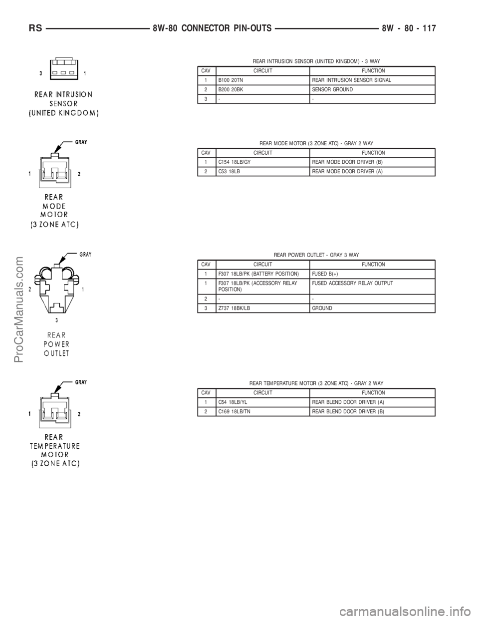
REAR INTRUSION SENSOR (UNITED KINGDOM)-3WAY
CAV CIRCUIT FUNCTION
1 B100 20TN REAR INTRUSION SENSOR SIGNAL
2 B200 20BK SENSOR GROUND
3- -
REAR MODE MOTOR (3 ZONE ATC) - GRAY 2 WAY
CAV CIRCUIT FUNCTION
1 C154 18LB/GY REAR MODE DOOR DRIVER (B)
2 C53 18LB REAR MODE DOOR DRIVER (A)
REAR POWER OUTLET - GRAY 3 WAY
CAV CIRCUIT FUNCTION
1 F307 18LB/PK (BATTERY POSITION) FUSED B(+)
1 F307 18LB/PK (ACCESSORY RELAY
POSITION)FUSED ACCESSORY RELAY OUTPUT
2- -
3 Z737 18BK/LB GROUND
REAR TEMPERATURE MOTOR (3 ZONE ATC) - GRAY 2 WAY
CAV CIRCUIT FUNCTION
1 C54 18LB/YL REAR BLEND DOOR DRIVER (A)
2 C169 18LB/TN REAR BLEND DOOR DRIVER (B)
RS8W-80 CONNECTOR PIN-OUTS8W - 80 - 117
ProCarManuals.com
Page 1116 of 2177
8W-91 CONNECTOR/GROUND/SPLICE LOCATION
TABLE OF CONTENTS
page
CONNECTOR/GROUND/SPLICE LOCATION
DESCRIPTION..........................1
CONNECTOR/GROUND/SPLICE
LOCATION
DESCRIPTION
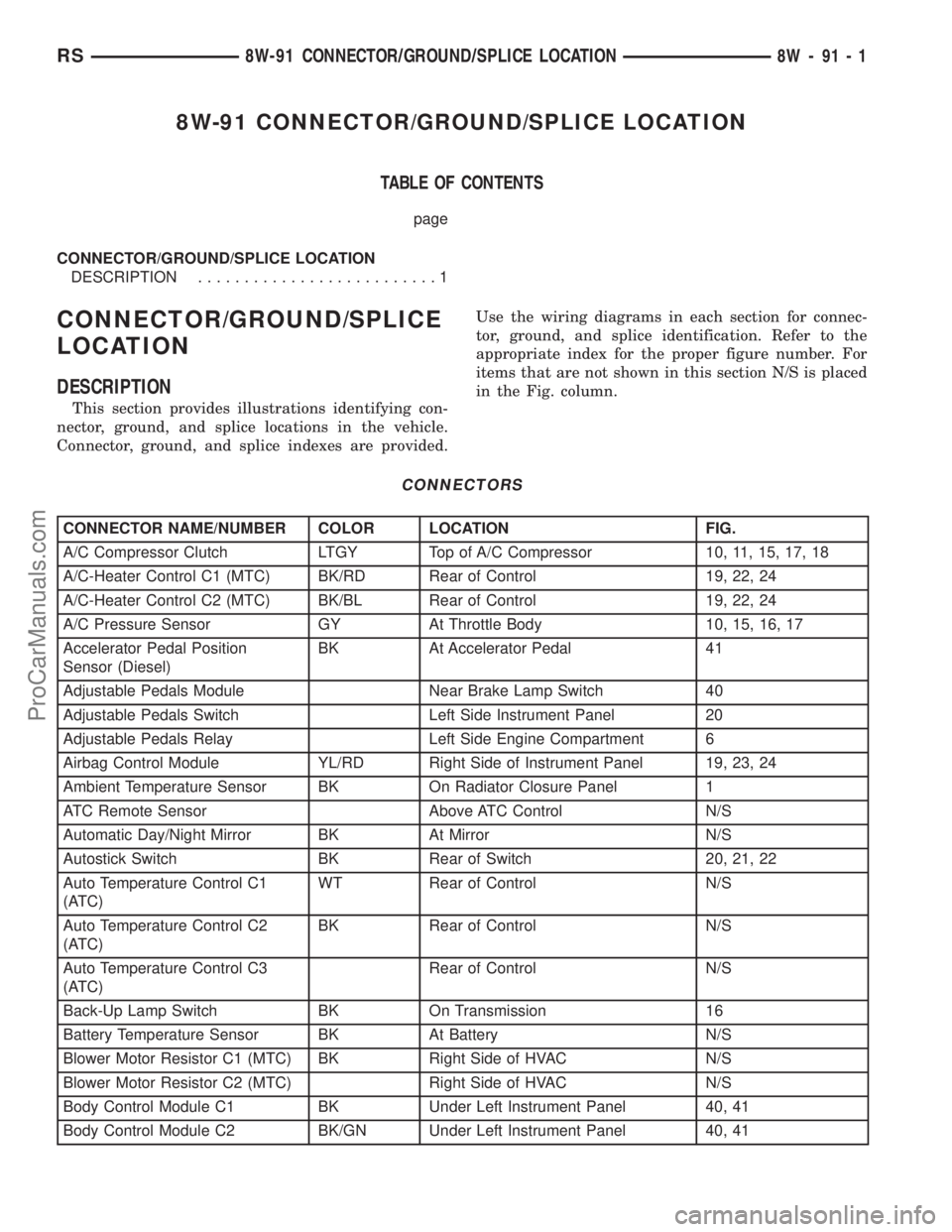
This section provides illustrations identifying con-
nector, ground, and splice locations in the vehicle.
Connector, ground, and splice indexes are provided.Use the wiring diagrams in each section for connec-
tor, ground, and splice identification. Refer to the
appropriate index for the proper figure number. For
items that are not shown in this section N/S is placed
in the Fig. column.
CONNECTORS
CONNECTOR NAME/NUMBER COLOR LOCATION FIG.
A/C Compressor Clutch LTGY Top of A/C Compressor 10, 11, 15, 17, 18
A/C-Heater Control C1 (MTC) BK/RD Rear of Control 19, 22, 24
A/C-Heater Control C2 (MTC) BK/BL Rear of Control 19, 22, 24
A/C Pressure Sensor GY At Throttle Body 10, 15, 16, 17
Accelerator Pedal Position
Sensor (Diesel)BK At Accelerator Pedal 41
Adjustable Pedals Module Near Brake Lamp Switch 40
Adjustable Pedals Switch Left Side Instrument Panel 20
Adjustable Pedals Relay Left Side Engine Compartment 6
Airbag Control Module YL/RD Right Side of Instrument Panel 19, 23, 24
Ambient Temperature Sensor BK On Radiator Closure Panel 1
ATC Remote Sensor Above ATC Control N/S
Automatic Day/Night Mirror BK At Mirror N/S
Autostick Switch BK Rear of Switch 20, 21, 22
Auto Temperature Control C1
(ATC)WT Rear of Control N/S
Auto Temperature Control C2
(ATC)BK Rear of Control N/S
Auto Temperature Control C3
(ATC)Rear of Control N/S
Back-Up Lamp Switch BK On Transmission 16
Battery Temperature Sensor BK At Battery N/S
Blower Motor Resistor C1 (MTC) BK Right Side of HVAC N/S
Blower Motor Resistor C2 (MTC) Right Side of HVAC N/S
Body Control Module C1 BK Under Left Instrument Panel 40, 41
Body Control Module C2 BK/GN Under Left Instrument Panel 40, 41
RS8W-91 CONNECTOR/GROUND/SPLICE LOCATION8W-91-1
ProCarManuals.com
Page 1120 of 2177
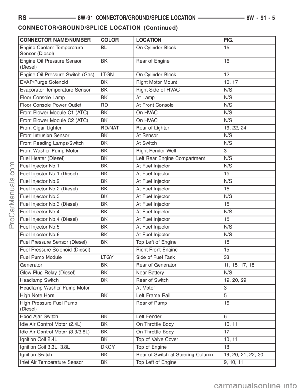
CONNECTOR NAME/NUMBER COLOR LOCATION FIG.
Engine Coolant Temperature
Sensor (Diesel)BL On Cylinder Block 15
Engine Oil Pressure Sensor
(Diesel)BK Rear of Engine 16
Engine Oil Pressure Switch (Gas) LTGN On Cylinder Block 12
EVAP/Purge Solenoid BK Right Motor Mount 10, 17
Evaporator Temperature Sensor BK Right Side of HVAC N/S
Floor Console Lamp BK At Lamp N/S
Floor Console Power Outlet RD At Front Console N/S
Front Blower Module C1 (ATC) BK On HVAC N/S
Front Blower Module C2 (ATC) BK On HVAC N/S
Front Cigar Lighter RD/NAT Rear of Lighter 19, 22, 24
Front Intrusion Sensor BK At Sensor N/S
Front Reading Lamps/Switch BK At Switch N/S
Front Washer Pump Motor BK Right Fender Well 3
Fuel Heater (Diesel) BK Left Rear Engine Compartment N/S
Fuel Injector No.1 BK At Fuel Injector N/S
Fuel Injector No.1 (Diesel) BK At Fuel Injector 15
Fuel Injector No.2 BK At Fuel Injector N/S
Fuel Injector No.2 (Diesel) BK At Fuel Injector 15
Fuel Injector No.3 BK At Fuel Injector N/S
Fuel Injector No.3 (Diesel) BK At Fuel Injector 15
Fuel Injector No.4 BK At Fuel Injector N/S
Fuel Injector No.4 (Diesel) BK At Fuel Injector 15
Fuel Injector No.5 BK At Fuel Injector N/S
Fuel Injector No.6 BK At Fuel Injector N/S
Fuel Pressure Sensor (Diesel) BK Top Left of Engine 15
Fuel Pressure Solenoid (Diesel) Right Front Engine 15
Fuel Pump Module LTGY Side of Fuel Tank 33
Generator BK Rear of Generator 11, 15, 17, 18
Glow Plug Relay (Diesel) BK Near Battery N/S
Headlamp Switch BK Rear of Switch 19, 20, 29
Headlamp Washer Pump Motor At Motor 3
High Note Horn BK Left Frame Rail 5
High Pressure Fuel Pump
(Diesel)Rear of Pump 15
Hood Ajar Switch BK Left Fender 6
Idle Air Control Motor (2.4L) BK On Throttle Body 10, 11
Idle Air Control Motor (3.3/3.8L) BK On Throttle Body 17
Ignition Coil 2.4L BK Top of Valve Cover 10, 11
Ignition Coil 3.3L, 3.8L DKGY Top of Engine 18
Ignition Switch BK Rear of Switch at Steering Column 19, 20, 21, 22, 30
Inlet Air Temperature Sensor BK Top Left of Engine 9, 10, 11
RS8W-91 CONNECTOR/GROUND/SPLICE LOCATION8W-91-5
CONNECTOR/GROUND/SPLICE LOCATION (Continued)
ProCarManuals.com
Page 1127 of 2177
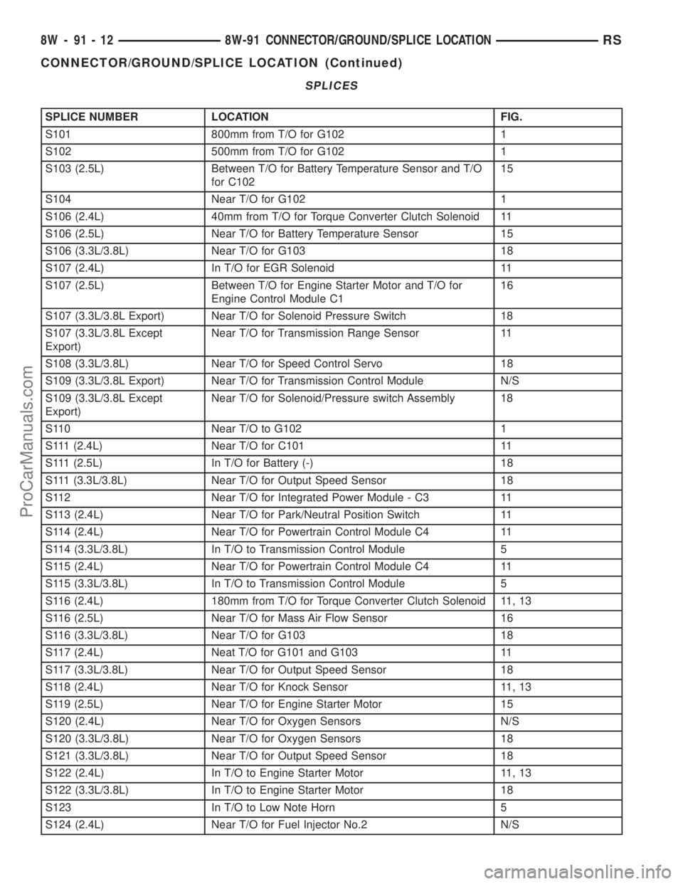
SPLICES
SPLICE NUMBER LOCATION FIG.
S101 800mm from T/O for G102 1
S102 500mm from T/O for G102 1
S103 (2.5L) Between T/O for Battery Temperature Sensor and T/O
for C10215
S104 Near T/O for G102 1
S106 (2.4L) 40mm from T/O for Torque Converter Clutch Solenoid 11
S106 (2.5L) Near T/O for Battery Temperature Sensor 15
S106 (3.3L/3.8L) Near T/O for G103 18
S107 (2.4L) In T/O for EGR Solenoid 11
S107 (2.5L) Between T/O for Engine Starter Motor and T/O for
Engine Control Module C116
S107 (3.3L/3.8L Export) Near T/O for Solenoid Pressure Switch 18
S107 (3.3L/3.8L Except
Export)Near T/O for Transmission Range Sensor 11
S108 (3.3L/3.8L) Near T/O for Speed Control Servo 18
S109 (3.3L/3.8L Export) Near T/O for Transmission Control Module N/S
S109 (3.3L/3.8L Except
Export)Near T/O for Solenoid/Pressure switch Assembly 18
S110 Near T/O to G102 1
S111 (2.4L) Near T/O for C101 11
S111 (2.5L) In T/O for Battery (-) 18
S111 (3.3L/3.8L) Near T/O for Output Speed Sensor 18
S112 Near T/O for Integrated Power Module - C3 11
S113 (2.4L) Near T/O for Park/Neutral Position Switch 11
S114 (2.4L) Near T/O for Powertrain Control Module C4 11
S114 (3.3L/3.8L) In T/O to Transmission Control Module 5
S115 (2.4L) Near T/O for Powertrain Control Module C4 11
S115 (3.3L/3.8L) In T/O to Transmission Control Module 5
S116 (2.4L) 180mm from T/O for Torque Converter Clutch Solenoid 11, 13
S116 (2.5L) Near T/O for Mass Air Flow Sensor 16
S116 (3.3L/3.8L) Near T/O for G103 18
S117 (2.4L) Neat T/O for G101 and G103 11
S117 (3.3L/3.8L) Near T/O for Output Speed Sensor 18
S118 (2.4L) Near T/O for Knock Sensor 11, 13
S119 (2.5L) Near T/O for Engine Starter Motor 15
S120 (2.4L) Near T/O for Oxygen Sensors N/S
S120 (3.3L/3.8L) Near T/O for Oxygen Sensors 18
S121 (3.3L/3.8L) Near T/O for Output Speed Sensor 18
S122 (2.4L) In T/O to Engine Starter Motor 11, 13
S122 (3.3L/3.8L) In T/O to Engine Starter Motor 18
S123 In T/O to Low Note Horn 5
S124 (2.4L) Near T/O for Fuel Injector No.2 N/S
8W - 91 - 12 8W-91 CONNECTOR/GROUND/SPLICE LOCATIONRS
CONNECTOR/GROUND/SPLICE LOCATION (Continued)
ProCarManuals.com
Page 1128 of 2177

SPLICE NUMBER LOCATION FIG.
S124 (3.3L/3.8L) Near T/O for Fuel Injector No.5 and No.6 N/S
S125 (2.4L) In T/O for Manifold Absolute Pressure Sensor N/S
S126 In Right Headlamp Leveling Assembly N/S
S127 (2.5L) In T/O for Engine Starter Motor N/S
S128 (2.5L) Near T/O for Engine Starter Motor 15
S129 (2.5L) Near T/O for Battery (+) N/S
S130 (2.5L) Near T/O for Battery (+) N/S
S131 Near T/O for Transmission Control Module 11
S131 (3.3L/3.8L) Near T/O for Transmission Control Module N/S
S132 (2.5L) Near T/O for Battery (+) N/S
S133 (2.4L) Near T/O for Integrated Power Module C3 11
S134 (2.5L) IN T/O for Engine Control Module 15
S135 (2.5L) Near T/O for Glow Plug No.2 15
S136 (2.5L) In T/O for Radiator Fan Relays 2
S137 (2.5L) Near T/O for A/C Compressor Clutch 15
S138 (2.5L) Between T/O for Radiator Fan No.2 and T/O for G102 1
S139 (2.5L) Between T/O for Engine Starter Motor and T/O for
Engine Control Module C116
S141 (2.4L) Near T/O for Battery(-) 11
S141 (2.5L) Near T/O for G100 N/S
S141 (3.3L/3.8L) Near T/O for Powertrain Control Module N/S
S142 (3.3L/3.8L) Near T/O for A/C Compressor Clutch 18
S143 (2.5L) Near T/O for Engine Control Module C1 15
S143 (3.3L/3.8L) Near T/O for Integrated Power Module - C3 N/S
S144 (2.5L) Between T/O for Battery Temperature Sensor and T/O
for C10315
S148 (2.5L) Near T/O for Engine Starter Motor 15
S149 (3.3L/3.8L) Near T/O for Transmission Control Module 5
S150 (2.5L) Between T/O for Battery Temperature Sensor and T/O
for C10315
S151 (2.5L) Near T/O for Radiator Fan Relay No.1 2
S152 (2.5L) Near T/O for Radiator Fan No.1 1
S157 (2.5L) Near T/O for Glow Plug No.1 15
S177 In Right Headlamp Wiring Assembly N/S
S179 In Left Headlamp Wiring Assembly N/S
S187 (2.5L) In T/O for Engine Control Module C1 15
S188 (2.5L) Near T/O for Radiator Fan Relay No.1 2
S201 In T/O to Instrument Panel Speaker 19, 25
S202 Near T/O for Instrument Panel Switch Bank 19, 25
S203 Near T/O for Instrument Panel Switch Bank 19, 25
S204 Near T/O to Instrument Panel Speaker 19, 25
S205 Near T/O for C201 19
S206 Near T/O for Instrument Cluster 19
RS8W-91 CONNECTOR/GROUND/SPLICE LOCATION8W-91-13
CONNECTOR/GROUND/SPLICE LOCATION (Continued)
ProCarManuals.com
Page 1175 of 2177
SPECIAL TOOLS
POWER DISTRIBUTION SYSTEMS
ACCESSORY RELAY
DESCRIPTION
The accessory relay is an electromechanical device
that switches fused battery current to the accessory
powered vehicle circuits when the ignition switch is
turned to the Accessory or On positions. The delay
feature will maintain power to the accessories for 45
seconds after the ignition is shut off or until a door is
opened. This allows sufficient time to close windows
and park the windshield wipers. The accessory relay
is located in the Integrated Power Module (IPM) in
the engine compartment.
The accessory relay is a International Standards
Organization (ISO) relay. Relays conforming to the
ISO specifications have common physical dimensions,
current capacities, terminal patterns, and terminal
functions.
The accessory relay cannot be repaired or adjusted
and, if faulty or damaged, it must be replaced.
OPERATION
The ISO relay consists of an electromagnetic coil, a
resistor or diode, and three (two fixed and one mov-
able) electrical contacts. The movable (common feed)
relay contact is held against one of the fixed contacts
(normally closed) by spring pressure. When the elec-
tromagnetic coil is energized, it draws the movable
contact away from the normally closed fixed contact,
and holds it against the other (normally open) fixed
contact.
When the electromagnetic coil is de-energized,
spring pressure returns the movable contact to the
normally closed position. The resistor or diode is con-
nected in parallel with the electromagnetic coil in therelay, and helps to dissipate voltage spikes that are
produced when the coil is de-energized.
DIAGNOSIS AND TESTING
DIAGNOSIS & TESTING - ACCESSORY RELAY
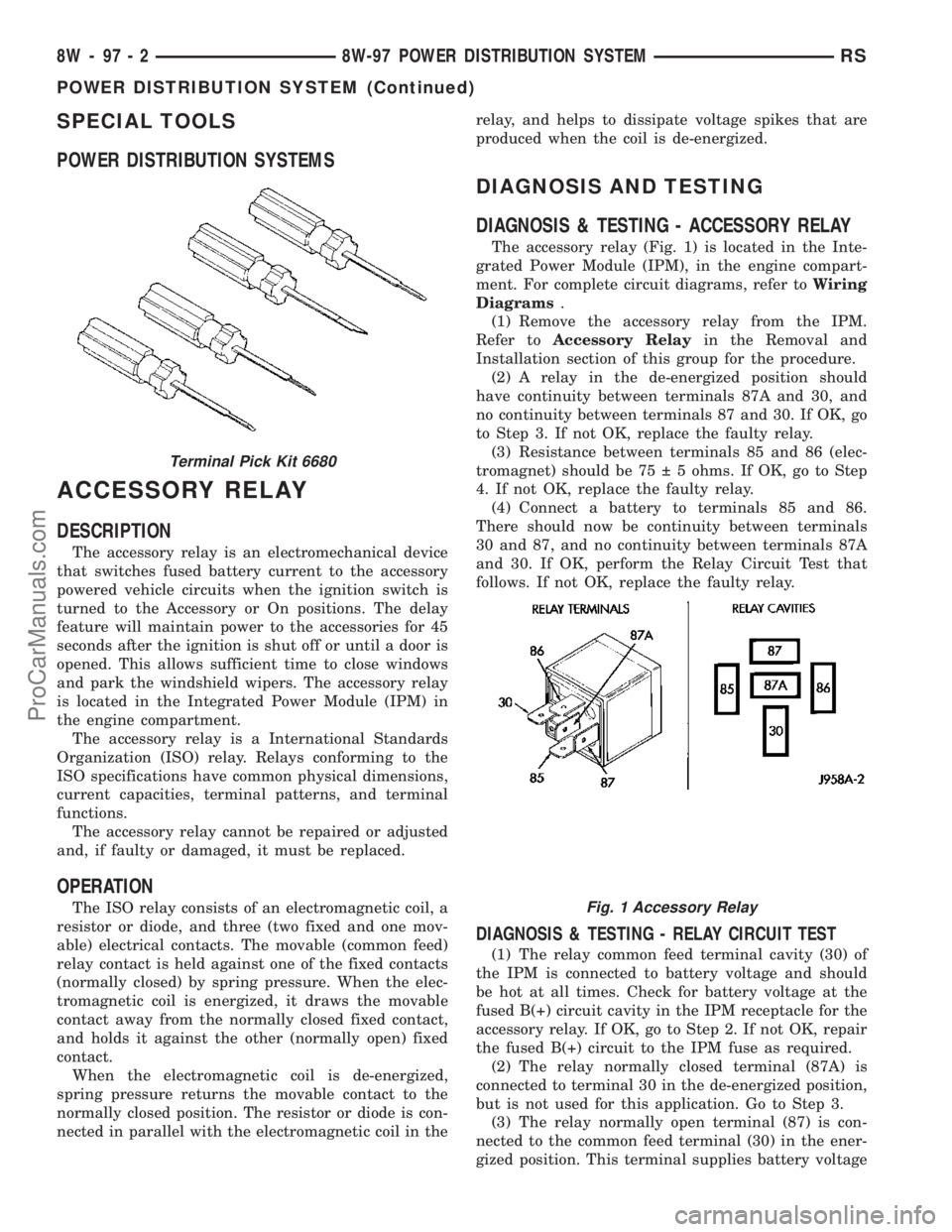
The accessory relay (Fig. 1) is located in the Inte-
grated Power Module (IPM), in the engine compart-
ment. For complete circuit diagrams, refer toWiring
Diagrams.
(1) Remove the accessory relay from the IPM.
Refer toAccessory Relayin the Removal and
Installation section of this group for the procedure.
(2) A relay in the de-energized position should
have continuity between terminals 87A and 30, and
no continuity between terminals 87 and 30. If OK, go
to Step 3. If not OK, replace the faulty relay.
(3) Resistance between terminals 85 and 86 (elec-
tromagnet) should be 75 5 ohms. If OK, go to Step
4. If not OK, replace the faulty relay.
(4) Connect a battery to terminals 85 and 86.
There should now be continuity between terminals
30 and 87, and no continuity between terminals 87A
and 30. If OK, perform the Relay Circuit Test that
follows. If not OK, replace the faulty relay.
DIAGNOSIS & TESTING - RELAY CIRCUIT TEST
(1) The relay common feed terminal cavity (30) of
the IPM is connected to battery voltage and should
be hot at all times. Check for battery voltage at the
fused B(+) circuit cavity in the IPM receptacle for the
accessory relay. If OK, go to Step 2. If not OK, repair
the fused B(+) circuit to the IPM fuse as required.
(2) The relay normally closed terminal (87A) is
connected to terminal 30 in the de-energized position,
but is not used for this application. Go to Step 3.
(3) The relay normally open terminal (87) is con-
nected to the common feed terminal (30) in the ener-
gized position. This terminal supplies battery voltage
Terminal Pick Kit 6680
Fig. 1 Accessory Relay
8W - 97 - 2 8W-97 POWER DISTRIBUTION SYSTEMRS
POWER DISTRIBUTION SYSTEM (Continued)
ProCarManuals.com
Page 1176 of 2177
to the fused B(+) fuse in the IPM that feeds the
accessories when the relay is energized by the igni-
tion switch. There should be continuity between the
IPM cavity for relay terminal 87 and the fused B(+)
fuse in the IPM at all times. If OK, go to Step 4. If
not OK, repair the open fused B(+) circuit to the IPM
fuse as required.
(4) The coil ground terminal (85) is connected to
the electromagnet in the relay. It receives battery
feed to energize the accessory relay when the ignition
switch is in the Accessory or On positions. Turn the
ignition switch to the On position. Check for battery
voltage at the fused ignition switch output (acc/run)
circuit cavity for relay terminal 85 in the IPM recep-
tacle for the accessory relay. If OK, go to Step 5. If
not OK, repair the open fused ignition switch output
(acc/run) circuit to the ignition switch as required.
(5) The coil battery terminal (86) is connected to
the electromagnet in the relay. The IPM cavity for
this terminal should have continuity to ground at all
times. If not OK, repair the open ground circuit to
ground as required.
REMOVAL
(1) Disconnect and isolate the battery negative
cable.
(2) Remove the Integrated Power Module (IPM)
cover from the IPM.
(3) Remove the accessory relay from the IPM.
Refer to the IPM cover for relay location.
INSTALLATION
(1) Position the accessory relay in the proper
receptacle in the Integrated Power Module (IPM).
(2) Push in firmly on the accessory relay until the
terminals are fully seated in the terminal cavities in
the IPM receptacle.
(3) Install the IPM cover.
(4) Reconnect the battery negative cable.
INTEGRATED POWER MODULE
DESCRIPTION
The Integrated Power Module (IPM) is a combina-
tion of the Power Distribution Center (PDC) and the
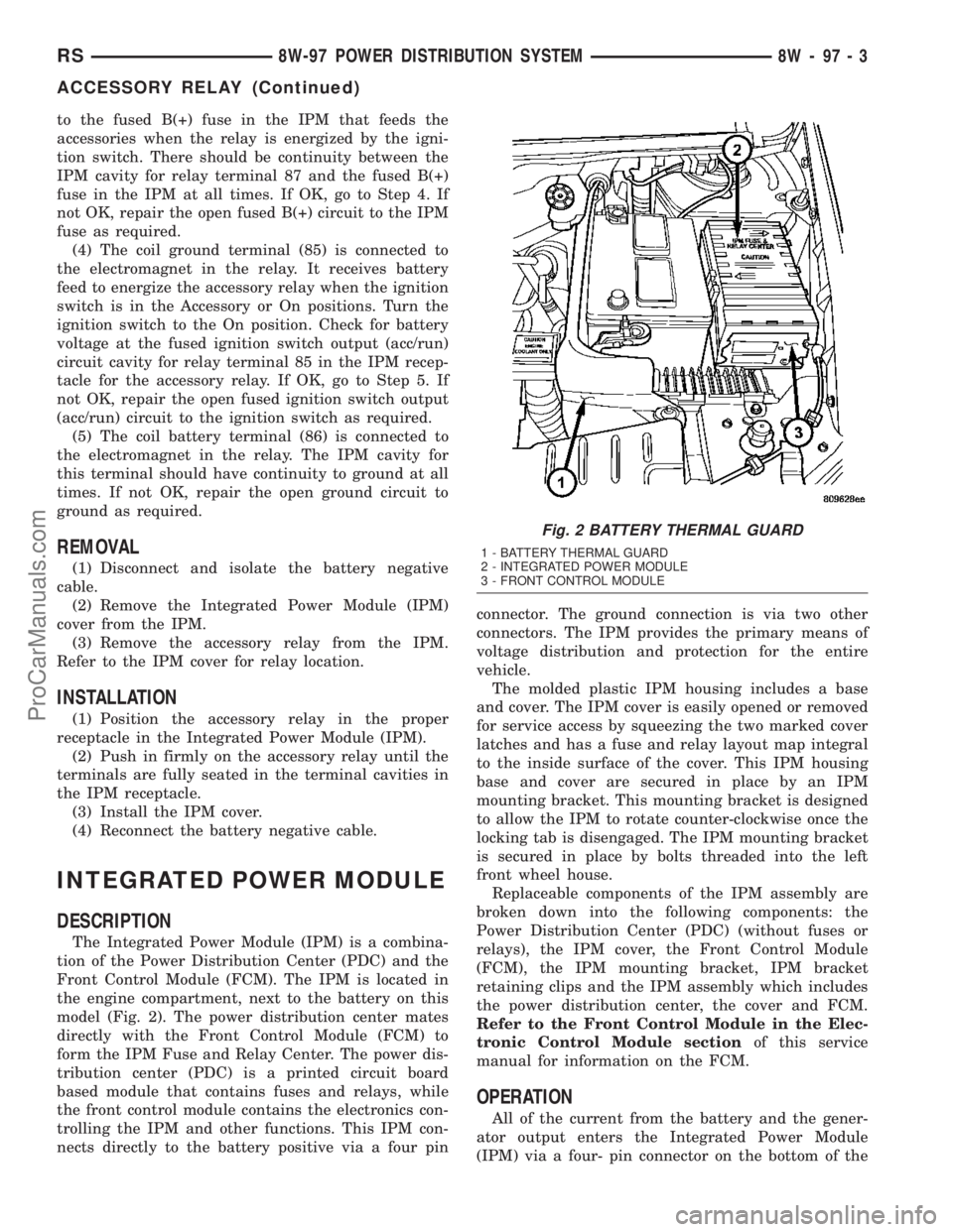
Front Control Module (FCM). The IPM is located in
the engine compartment, next to the battery on this
model (Fig. 2). The power distribution center mates
directly with the Front Control Module (FCM) to
form the IPM Fuse and Relay Center. The power dis-
tribution center (PDC) is a printed circuit board
based module that contains fuses and relays, while
the front control module contains the electronics con-
trolling the IPM and other functions. This IPM con-
nects directly to the battery positive via a four pinconnector. The ground connection is via two other
connectors. The IPM provides the primary means of
voltage distribution and protection for the entire
vehicle.
The molded plastic IPM housing includes a base
and cover. The IPM cover is easily opened or removed
for service access by squeezing the two marked cover
latches and has a fuse and relay layout map integral
to the inside surface of the cover. This IPM housing
base and cover are secured in place by an IPM
mounting bracket. This mounting bracket is designed
to allow the IPM to rotate counter-clockwise once the
locking tab is disengaged. The IPM mounting bracket
is secured in place by bolts threaded into the left
front wheel house.
Replaceable components of the IPM assembly are
broken down into the following components: the
Power Distribution Center (PDC) (without fuses or
relays), the IPM cover, the Front Control Module
(FCM), the IPM mounting bracket, IPM bracket
retaining clips and the IPM assembly which includes
the power distribution center, the cover and FCM.
Refer to the Front Control Module in the Elec-
tronic Control Module sectionof this service
manual for information on the FCM.
OPERATION
All of the current from the battery and the gener-
ator output enters the Integrated Power Module
(IPM) via a four- pin connector on the bottom of the
Fig. 2 BATTERY THERMAL GUARD
1 - BATTERY THERMAL GUARD
2 - INTEGRATED POWER MODULE
3 - FRONT CONTROL MODULE
RS8W-97 POWER DISTRIBUTION SYSTEM8W-97-3
ACCESSORY RELAY (Continued)
ProCarManuals.com