2003 CHRYSLER CARAVAN wheel size
[x] Cancel search: wheel sizePage 1725 of 2177

RCONSTRUCTION
TYPER - RADIAL
B - BIAS BELTED
D - DIAGONAL (BIAS)
16WHEEL DIAMETER SHOWN IN INCHES
97LOAD INDEX *
TSPEED RATING *
* NOTE: Consult the tire manufacturer regarding
any questions on tire specifications or capabilities.
TIRE CHAINS
Refer to the owners manual supplied with the vehi-
cle to determine whether the use of tire chains is per-
mitted on this vehicle.
DESCRIPTION - RADIAL-PLY TIRES
Radial-ply tires improve handling, tread life, ride
quality and decrease rolling resistance.
Radial-ply tires must always be used in sets of four
and under no circumstances should they be used on
the front only. It is recommended that tires from dif-
ferent manufacturers NOT be mixed. They may be
mixed with a temporary spare tire when necessary. A
maximum speed of 80 km/h (50 mph) is recom-
mended while a temporary spare is in use.
Radial-ply tires have the same load-carrying capac-
ity as other types of tires of the same size. They also
use the same recommended inflation pressures.
DESCRIPTION - REPLACEMENT TIRES
WARNING: FAILURE TO EQUIP THE VEHICLE WITH
TIRES HAVING ADEQUATE SPEED CAPABILITY
CAN RESULT IN SUDDEN TIRE FAILURE.It is recommended that tires equivalent to the orig-
inal equipment tires be used when replacement is
needed.
Failure to use equivalent replacement tires may
adversely affect the safety and handling of the vehi-
cle.
The original equipment tires provide a proper com-
bination of many characteristics such as:
²Ride
²Noise
²Handling
²Durability
²Tread life
²Traction
²Rolling resistance
²Speed capability
The use of tires smaller than the minimum tire
size approved for the vehicle can result in tire over-
loading and failure.
Use tires that have the approved load rating for
the vehicle and never overload them. Failure to equip
the vehicle with tires having adequate speed capabil-
ity can result in sudden tire failure and loss of vehi-
cle control.
The use of oversize tires may cause interference
with vehicle components. Under extremes of suspen-
sion and steering travel, interference with vehicle
components may cause tire damage.
DESCRIPTION - SPARE TIRE (TEMPORARY)
The temporary (convenience) spare tire is designed
for emergency use only. The original tire should be
repaired and reinstalled, or replaced with a new, at
the first opportunity.
The temporary (convenience) spare tire should be
inflated to the pressure listed on its sidewall. Do not
exceed speeds of 80 km/h (50 mph) when the tempo-
rary spare tire is in use on the vehicle. Refer to the
Owner's Manual for more details.
DIAGNOSIS AND TESTING
DIAGNOSIS AND TESTING - TIRE NOISE
Unusual tire noise can be associated with tire and
wheel vibration or irregular tire wear. For vibration,
(Refer to 22 - TIRES/WHEELS - DIAGNOSIS AND
TESTING). For irregular tire wear, (Refer to 22 -
TIRES/WHEELS/TIRES - DIAGNOSIS AND TEST-
ING).
DIAGNOSIS AND TESTING - TIRE/VEHICLE
LEAD
Use the following Vehicle Lead Diagnosis And Cor-
rection Chart to diagnose and correct a vehicle lead
or drift problem.
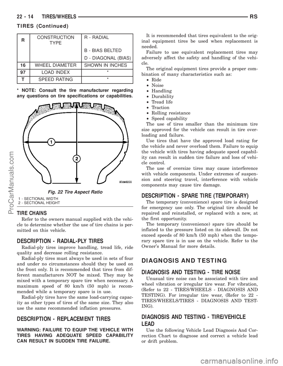
Fig. 22 Tire Aspect Ratio
1 - SECTIONAL WIDTH
2 - SECTIONAL HEIGHT
22 - 14 TIRES/WHEELSRS
TIRES (Continued)
ProCarManuals.com
Page 1730 of 2177

Care must be taken in the selection of tire and
wheel cleaning chemicals and equipment to prevent
damage to the wheels. Any of the ªDO NOT USEº
items listed below WILL damage chrome plated and
painted aluminum wheels.
DO NOT USE:
²any abrasive metal cleaner
²any abrasive cleaning pad or brush
²any cleaner that contains an acid (this will
immediately react with and discolor the chromium
surface)
²chrome polish (unless it is buffed off immedi-
ately after application)
²oven cleaner
²a car wash that uses carbide-tipped wheel clean-
ing brushes
SPECIFICATIONS
WHEEL
SPECIFICATIONS
DESCRIPTION SPECIFICATION
Wheel Mounting (Lug)
Nut Hex Size19 mm
Wheel Mounting Stud
SizeM12 x 1.5 mm
TORQUE SPECIFICATIONS
DESCRIPTION N´mFt.
Lbs.In.
Lbs.
TPM Sensor Mounting Nut 4 Ð 35
Wheel Mounting (Lug ) Nut 135 100 Ð
WHEEL COVER
DESCRIPTION
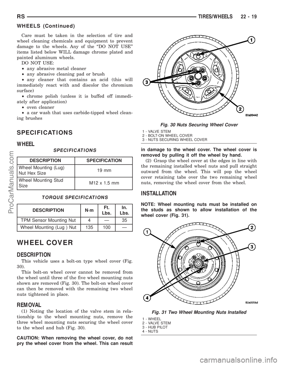
This vehicle uses a bolt-on type wheel cover (Fig.
30).
This bolt-on wheel cover cannot be removed from
the wheel until three of the five wheel mounting nuts
shown are removed (Fig. 30). The bolt-on wheel cover
can then be removed with the remaining two wheel
nuts tightened in place.
REMOVAL
(1) Noting the location of the valve stem in rela-
tionship to the wheel mounting nuts, remove the
three wheel mounting nuts securing the wheel cover
to the wheel and hub (Fig. 30).
CAUTION: When removing the wheel cover, do not
pry the wheel cover from the wheel. This can resultin damage to the wheel cover. The wheel cover is
removed by pulling it off the wheel by hand.
(2) Grasp the wheel cover at the edges in line with
the remaining installed wheel nuts and pull straight
outward from the wheel. This will pop the wheel
cover retaining tabs over the two remaining wheel
nuts, removing the wheel cover from the wheel.
INSTALLATION
NOTE: Wheel mounting nuts must be installed on
the studs as shown to allow installation of the
wheel cover (Fig. 31).
Fig. 30 Nuts Securing Wheel Cover
1 - VALVE STEM
2 - BOLT-ON WHEEL COVER
3 - NUTS SECURING WHEEL COVER
Fig. 31 Two Wheel Mounting Nuts Installed
1 - WHEEL
2 - VALVE STEM
3 - HUB PILOT
4 - NUTS
RSTIRES/WHEELS22-19
WHEELS (Continued)
ProCarManuals.com
Page 2069 of 2177

the notched area between the upper and lower hous-
ing halves.
(3) Install and tighten the twelve screws around
the perimeter of the evaporator housing that secure
the upper housing half to the lower half. Tighten the
screws to 2 N´m (18 in. lbs.).
(4) Position the upper half of the recirculation air
door onto the lower half of the door.
(5) Install and tighten the two screws that secure
the upper half of the recirculation air door to the
lower half of the door. Tighten the screws to 2 N´m
(18 in. lbs.).
(6) Position the upper intake air housing onto the
top of the evaporator housing over the recirculation
air door and the blower wheel housing. Be certain
that the upper pivot of the recirculation air door is
captured in the pivot receptacle of the upper intake
air housing.
(7) Install and tighten the three screws that secure
the upper intake air housing to the top of the out-
board end of the evaporator housing. Be certain not
to miss the screw located just inside the inboard side
of the fresh air intake opening. Tighten the screws to
2 N´m (18 in. lbs.).
(8) Install and tighten the two screws that secure
the upper intake air housing to the lower intake air
housing. Tighten the screws to 2 N´m (18 in. lbs.).
(9) Engage the two hook formations on the bottom
of the distribution housing in the two receptacles on
the evaporator housing.
(10) Roll the top of the distribution housing up
into position against the evaporator housing.
(11) Install and tighten the three screws from the
dash panel side of the unit that secure the top of the
distribution housing to the inboard end of the evapo-
rator housing. Tighten the screws to 2 N´m (18 in.
lbs.).
(12) Engage the HVAC wire harness in the routing
clips molded into the outside of the HVAC housing
components.
(13) Reconnect the HVAC wire harness connector
for the blower motor with the motor connector recep-
tacle on the bottom of the outboard end of the evap-
orator housing.
(14) Reinstall the expansion valve onto the evapo-
rator inlet and outlet tube fittings. (Refer to 24 -
HEATING & AIR CONDITIONING/PLUMBING -
FRONT/EXPANSION VALVE - INSTALLATION).
(15) Install a new foam seal onto the HVAC hous-
ing seal flange around the fresh air inlet opening and
the expansion valve/evaporator tube opening on the
dash panel side of the unit.
(16) Reinstall the heater core tubes into the heater
core. (Refer to 24 - HEATING & AIR CONDITION-
ING/PLUMBING - FRONT/HEATER CORE -
INSTALLATION - HEATER CORE TUBES).(17) Reinstall the HVAC unit housing into the
vehicle. (Refer to 24 - HEATING & AIR CONDI-
TIONING/DISTRIBUTION - FRONT/HVAC HOUS-
ING - INSTALLATION).
(18) Run the HVAC Control Actuator Calibration
procedure(Refer to 24 - HEATING & AIR CONDI-
TIONING - DIAGNOSIS AND TESTING)(Refer to 24
- HEATING & AIR CONDITIONING - DIAGNOSIS
AND TESTING).
EXPANSION VALVE
DESCRIPTION
The front ªHº valve-type thermal expansion valve
(TXV) is located at the dash panel between the liquid
and suction lines, and the evaporator coil. The
assembly consists of an H-valve body and a thermal
sensor. High-pressure, low temperature liquid refrig-
erant from the liquid line passes through the expan-
sion valve orifice, converting it into a low-pressure,
low-temperature mixture of liquid and gas before it
enters the evaporator coil. The expansion valve is a
factory calibrated unit and cannot be adjusted or
repaired. If faulty or damaged, the expansion valve
must be replaced.
OPERATION
A mechanical sensor in the expansion valve control
head monitors the temperature and pressure of the
refrigerant leaving the evaporator coil through the
suction line, and adjusts the orifice size at the liquid
line to let the proper amount of refrigerant into the
evaporator coil to meet the vehicle cooling require-
ments. Controlling the refrigerant flow through the
evaporator ensures that none of the refrigerant leav-
ing the evaporator is still in a liquid state, which
could damage the compressor. The thermo sensor
measures refrigerant suction gas temperature which
is monitored by the a/c control assembly.
DIAGNOSIS AND TESTING - EXPANSION VALVE
WARNING: REFER TO THE APPLICABLE WARN-
INGS AND CAUTIONS FOR THIS SYSTEM BEFORE
PERFORMING THE FOLLOWING OPERATION.
(Refer to 24 - HEATING & AIR CONDITIONING/
PLUMBING - FRONT - WARNING - A/C PLUMBING)
and (Refer to 24 - HEATING & AIR CONDITIONING/
PLUMBING - FRONT - CAUTION - A/C PLUMBING).
NOTE: The expansion valve should only be tested
following testing of the compressor.
24 - 72 PLUMBING - FRONTRS
EVAPORATOR (Continued)
ProCarManuals.com
Page 2075 of 2177

on the front of the shield are engaged in the recepta-
cles in the two lower finger formations of the evapo-
rator housing near the dash panel.
(8) Install and tighten the three screws that secure
the heater core shield to the left end of the HVAC
distribution housing. Tighten the screws to 2 N´m (17
in. lbs.).
(9) Reinstall the silencer under the driver side end
of the instrument panel. (Refer to 23 - BODY/IN-
STRUMENT PANEL/INSTRUMENT PANEL
SILENCER - INSTALLATION).
(10) Reconnect the heater hoses to the heater hose
tubes. (Refer to 24 - HEATING & AIR CONDITION-
ING/PLUMBING - FRONT/HEATER HOSE -
INSTALLATION).
(11) Reconnect the battery negative cable.
(12) Refill the engine cooling system. (Refer to 7 -
COOLING - STANDARD PROCEDURE - COOLING
SYSTEM REFILL).
INSTALLATION - HEATER CORE
WARNING: REFER TO THE APPLICABLE WARN-
INGS AND CAUTIONS FOR THIS SYSTEM BEFORE
PERFORMING THE FOLLOWING OPERATION.
(Refer to 24 - HEATING & AIR CONDITIONING/
PLUMBING FRONT - WARNING - HEATER PLUMB-
ING).
WARNING: ON VEHICLES EQUIPPED WITH AIR-
BAGS, DISABLE THE AIRBAG SYSTEM BEFORE
ATTEMPTING ANY STEERING WHEEL, STEERING
COLUMN, OR INSTRUMENT PANEL COMPONENT
DIAGNOSIS OR SERVICE. DISCONNECT AND ISO-
LATE THE BATTERY NEGATIVE (GROUND) CABLE,
THEN WAIT TWO MINUTES FOR THE AIRBAG SYS-
TEM CAPACITOR TO DISCHARGE BEFORE PER-
FORMING FURTHER DIAGNOSIS OR SERVICE. THIS
IS THE ONLY SURE WAY TO DISABLE THE AIRBAG
SYSTEM. FAILURE TO TAKE THE PROPER PRE-
CAUTIONS COULD RESULT IN ACCIDENTAL AIR-
BAG DEPLOYMENT AND POSSIBLE PERSONAL
INJURY.
(1) While pushing the brake pedal downward and
pulling the accelerator pedal upward far enough for
clearance, slide the heater core into the distribution
housing.
(2) Install and tighten the two screws that secure
the heater core mounting plate to the distribution
housing. Tighten the screws to 2 N´m (17 in. lbs.).
(3) Remove the plugs or tape from the heater core
tube fittings and both heater core ports.
(4) Position both heater core tubes and the sealing
plate simultaneously to the heater core supply and
return ports.(5) The heater core tubes each have a slot that
must be indexed to a location tab within each of the
heater core ports. Adjust the position of the tubes as
required so that the sealing plate fits flush against
the heater core supply and return ports, which indi-
cates that the tubes are properly indexed.
(6) Install and tighten the screw that secures the
heater core tube sealing plate to the heater core sup-
ply and return ports. Tighten the screw to 3 N´m (27
in. lbs.).
(7) Position the heater core shield onto the distri-
bution housing. Be certain that the two location tabs
on the front of the shield are engaged in the recepta-
cles in the two lower finger formations of the evapo-
rator housing near the dash panel.
(8) Install and tighten the three screws that secure
the heater core shield to the left end of the HVAC
distribution housing. Tighten the screws to 2 N´m (17
in. lbs.).
(9) Reconnect the power brake booster input rod
(push rod) to the pin on the brake pedal arm(Refer to
5 - BRAKES/HYDRAULIC/MECHANICAL/POWER
BRAKE BOOSTER - INSTALLATION).
(10) Reinstall the brake lamp switch into its
mounting bracket(Refer to 8 - ELECTRICAL/LAMPS/
LIGHTING - EXTERIOR/BRAKE LAMP SWITCH -
INSTALLATION).
(11) Reinstall the silencer boot around the base of
the lower steering shaft on the dash panel.
(12) Reconnect the battery negative cable.
(13) Refill the engine cooling system. (Refer to 7 -
COOLING - STANDARD PROCEDURE - COOLING
SYSTEM REFILL).
(14) Operate system for two thermostat cycles to
assure elimination of air in the system.
HEATER HOSE
REMOVAL
There are several heater core plumbing configura-
tions used on this model, depending upon the engine
size and other optional equipment. One plumbing
configuration is used for all 2.4L engines (Fig. 21),
while the 3.3L and 3.8L engines have unique heater
return plumbing on the engine for models with or
without an optional engine oil cooler (Fig. 24) or (Fig.
25). There are also unique plumbing configurations
at the heater core for models with or without the
optional rear heater and air conditioner (Fig. 22) or
(Fig. 23). All models use a combination of formed
steel tubing and rubber hoses. In most cases, the
rubber hose is secured to the steel tubing with a
spring tension clamp.
24 - 78 PLUMBING - FRONTRS
HEATER CORE (Continued)
ProCarManuals.com