2003 CHRYSLER CARAVAN wheel
[x] Cancel search: wheelPage 1228 of 2177
FRONT MOUNT
REMOVAL
(1) Raise vehicle on hoist.
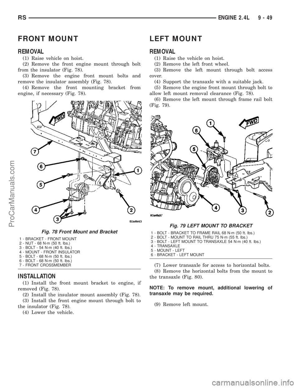
(2) Remove the front engine mount through bolt
from the insulator (Fig. 78).
(3) Remove the engine front mount bolts and
remove the insulator assembly (Fig. 78).
(4) Remove the front mounting bracket from
engine, if necessary (Fig. 78).
INSTALLATION
(1) Install the front mount bracket to engine, if
removed (Fig. 78).
(2) Install the insulator mount assembly (Fig. 78).
(3) Install the front engine mount through bolt to
the insulator (Fig. 78).
(4) Lower the vehicle.
LEFT MOUNT
REMOVAL
(1) Raise the vehicle on hoist.
(2) Remove the left front wheel.
(3) Remove the left mount through bolt access
cover.
(4) Support the transaxle with a suitable jack.
(5) Remove the engine front mount through bolt to
allow left mount removal clearance (Fig. 78).
(6) Remove the left mount through frame rail bolt
(Fig. 79).
(7) Lower transaxle for access to horizontal bolts.
(8) Remove the horizontal bolts from the mount to
the transaxle (Fig. 80).
NOTE: To remove mount, additional lowering of
transaxle may be required.
(9) Remove left mount.
Fig. 78 Front Mount and Bracket
1 - BRACKET - FRONT MOUNT
2 - NUT - 68 N´m (50 ft. lbs.)
3 - BOLT - 54 N´m (40 ft. lbs.)
4 - MOUNT - FRONT INSULATOR
5 - BOLT - 68 N´m (50 ft. lbs.)
6 - BOLT - 68 N´m (50 ft. lbs.)
7 - FRONT CROSSMEMBER
Fig. 79 LEFT MOUNT TO BRACKET
1 - BOLT - BRACKET TO FRAME RAIL 68 N´m (50 ft. lbs.)
2 - BOLT - MOUNT TO RAIL THRU 75 N´m (55 ft. lbs.)
3 - BOLT - LEFT MOUNT TO TRANSAXLE 54 N´m (40 ft. lbs.)
4 - TRANSAXLE
5 - MOUNT - LEFT
6 - BRACKET - LEFT MOUNT
RSENGINE 2.4L9-49
ProCarManuals.com
Page 1229 of 2177
INSTALLATION
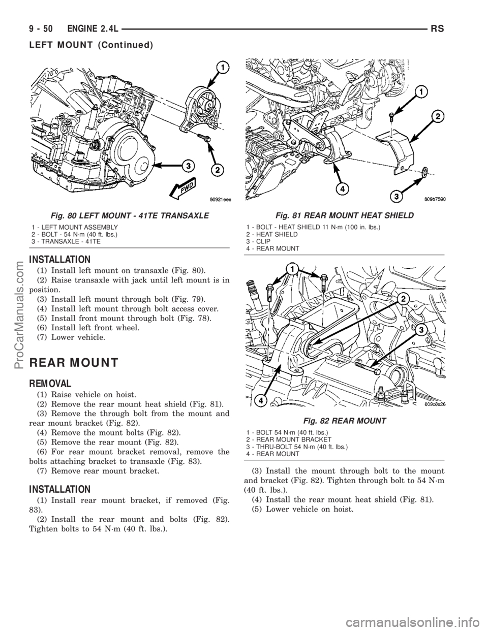
(1) Install left mount on transaxle (Fig. 80).
(2) Raise transaxle with jack until left mount is in
position.
(3) Install left mount through bolt (Fig. 79).
(4) Install left mount through bolt access cover.
(5) Install front mount through bolt (Fig. 78).
(6) Install left front wheel.
(7) Lower vehicle.
REAR MOUNT
REMOVAL
(1) Raise vehicle on hoist.
(2) Remove the rear mount heat shield (Fig. 81).
(3) Remove the through bolt from the mount and
rear mount bracket (Fig. 82).
(4) Remove the mount bolts (Fig. 82).
(5) Remove the rear mount (Fig. 82).
(6) For rear mount bracket removal, remove the
bolts attaching bracket to transaxle (Fig. 83).
(7) Remove rear mount bracket.
INSTALLATION
(1) Install rear mount bracket, if removed (Fig.
83).
(2) Install the rear mount and bolts (Fig. 82).
Tighten bolts to 54 N´m (40 ft. lbs.).(3) Install the mount through bolt to the mount
and bracket (Fig. 82). Tighten through bolt to 54 N´m
(40 ft. lbs.).
(4) Install the rear mount heat shield (Fig. 81).
(5) Lower vehicle on hoist.
Fig. 80 LEFT MOUNT - 41TE TRANSAXLE
1 - LEFT MOUNT ASSEMBLY
2 - BOLT - 54 N´m (40 ft. lbs.)
3 - TRANSAXLE - 41TE
Fig. 81 REAR MOUNT HEAT SHIELD
1 - BOLT - HEAT SHIELD 11 N´m (100 in. lbs.)
2 - HEAT SHIELD
3 - CLIP
4 - REAR MOUNT
Fig. 82 REAR MOUNT
1 - BOLT 54 N´m (40 ft. lbs.)
2 - REAR MOUNT BRACKET
3 - THRU-BOLT 54 N´m (40 ft. lbs.)
4 - REAR MOUNT
9 - 50 ENGINE 2.4LRS
LEFT MOUNT (Continued)
ProCarManuals.com
Page 1242 of 2177
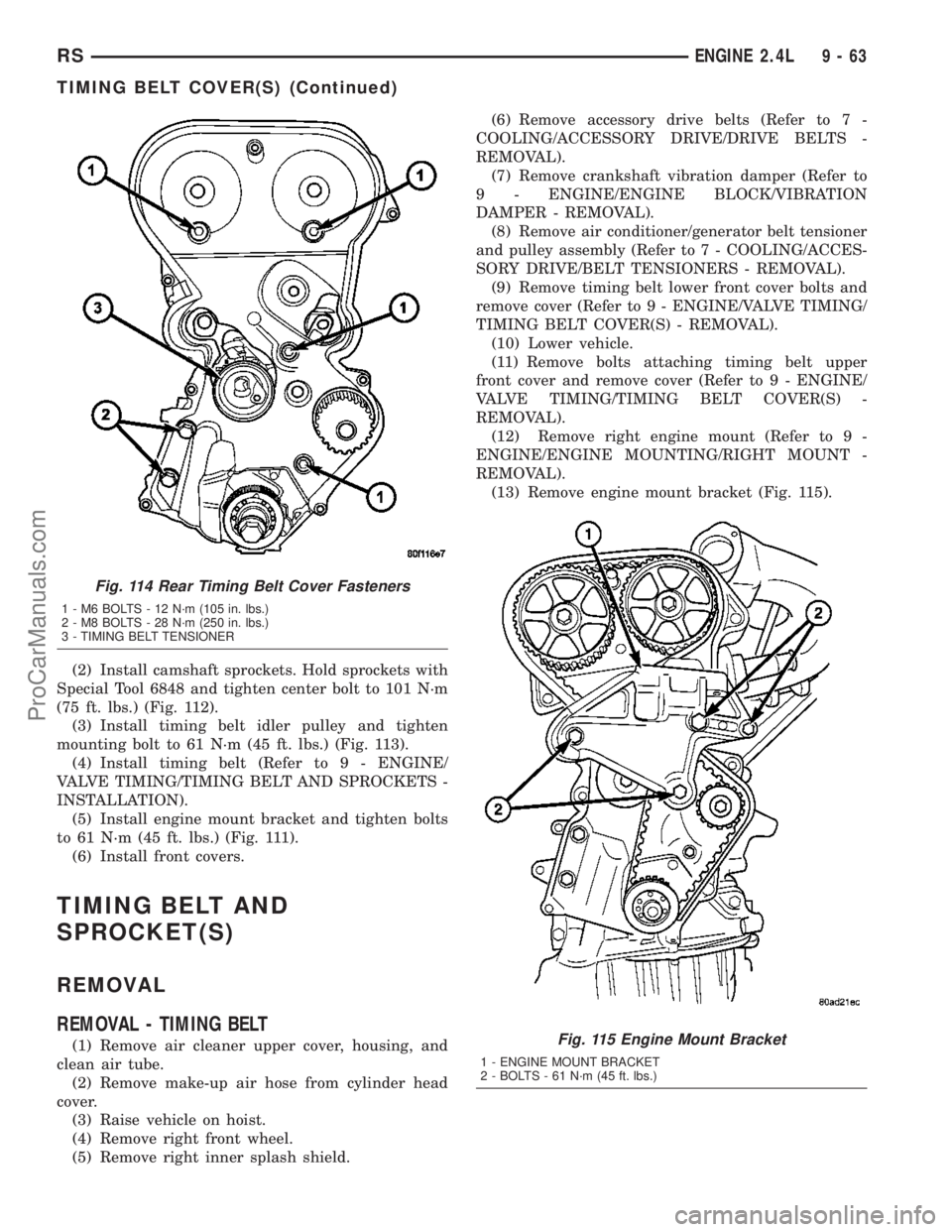
(2) Install camshaft sprockets. Hold sprockets with
Special Tool 6848 and tighten center bolt to 101 N´m
(75 ft. lbs.) (Fig. 112).
(3) Install timing belt idler pulley and tighten
mounting bolt to 61 N´m (45 ft. lbs.) (Fig. 113).
(4) Install timing belt (Refer to 9 - ENGINE/
VALVE TIMING/TIMING BELT AND SPROCKETS -
INSTALLATION).
(5) Install engine mount bracket and tighten bolts
to 61 N´m (45 ft. lbs.) (Fig. 111).
(6) Install front covers.
TIMING BELT AND
SPROCKET(S)
REMOVAL
REMOVAL - TIMING BELT
(1) Remove air cleaner upper cover, housing, and
clean air tube.
(2) Remove make-up air hose from cylinder head
cover.
(3) Raise vehicle on hoist.
(4) Remove right front wheel.
(5) Remove right inner splash shield.(6) Remove accessory drive belts (Refer to 7 -
COOLING/ACCESSORY DRIVE/DRIVE BELTS -
REMOVAL).
(7) Remove crankshaft vibration damper (Refer to
9 - ENGINE/ENGINE BLOCK/VIBRATION
DAMPER - REMOVAL).
(8) Remove air conditioner/generator belt tensioner
and pulley assembly (Refer to 7 - COOLING/ACCES-
SORY DRIVE/BELT TENSIONERS - REMOVAL).
(9) Remove timing belt lower front cover bolts and
remove cover (Refer to 9 - ENGINE/VALVE TIMING/
TIMING BELT COVER(S) - REMOVAL).
(10) Lower vehicle.
(11) Remove bolts attaching timing belt upper
front cover and remove cover (Refer to 9 - ENGINE/
VALVE TIMING/TIMING BELT COVER(S) -
REMOVAL).
(12) Remove right engine mount (Refer to 9 -
ENGINE/ENGINE MOUNTING/RIGHT MOUNT -
REMOVAL).
(13) Remove engine mount bracket (Fig. 115).
Fig. 114 Rear Timing Belt Cover Fasteners
1 - M6 BOLTS - 12 N´m (105 in. lbs.)
2 - M8 BOLTS - 28 N´m (250 in. lbs.)
3 - TIMING BELT TENSIONER
Fig. 115 Engine Mount Bracket
1 - ENGINE MOUNT BRACKET
2 - BOLTS - 61 N´m (45 ft. lbs.)
RSENGINE 2.4L9-63
TIMING BELT COVER(S) (Continued)
ProCarManuals.com
Page 1246 of 2177
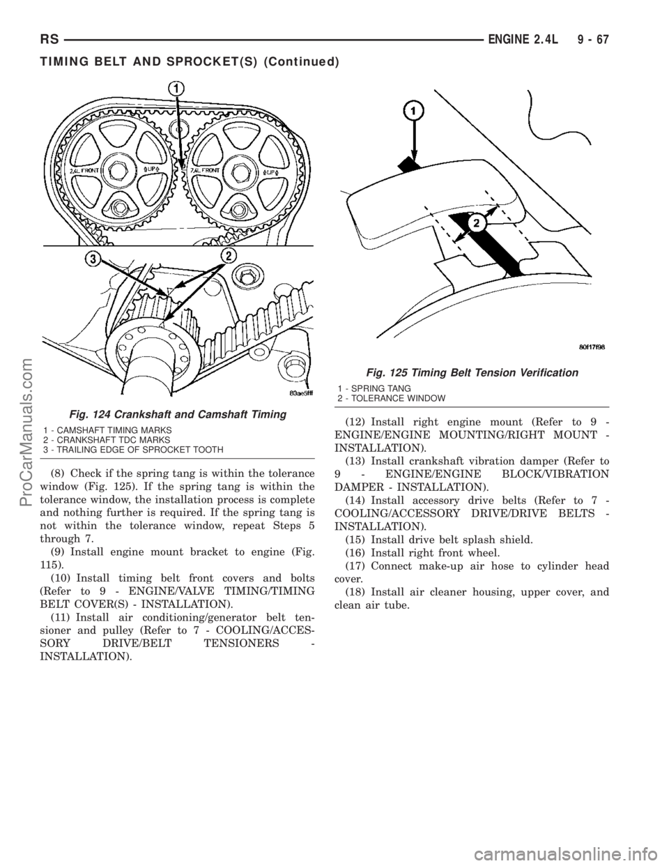
(8) Check if the spring tang is within the tolerance
window (Fig. 125). If the spring tang is within the
tolerance window, the installation process is complete
and nothing further is required. If the spring tang is
not within the tolerance window, repeat Steps 5
through 7.
(9) Install engine mount bracket to engine (Fig.
115).
(10) Install timing belt front covers and bolts
(Refer to 9 - ENGINE/VALVE TIMING/TIMING
BELT COVER(S) - INSTALLATION).
(11) Install air conditioning/generator belt ten-
sioner and pulley (Refer to 7 - COOLING/ACCES-
SORY DRIVE/BELT TENSIONERS -
INSTALLATION).(12) Install right engine mount (Refer to 9 -
ENGINE/ENGINE MOUNTING/RIGHT MOUNT -
INSTALLATION).
(13) Install crankshaft vibration damper (Refer to
9 - ENGINE/ENGINE BLOCK/VIBRATION
DAMPER - INSTALLATION).
(14) Install accessory drive belts (Refer to 7 -
COOLING/ACCESSORY DRIVE/DRIVE BELTS -
INSTALLATION).
(15) Install drive belt splash shield.
(16) Install right front wheel.
(17) Connect make-up air hose to cylinder head
cover.
(18) Install air cleaner housing, upper cover, and
clean air tube.
Fig. 124 Crankshaft and Camshaft Timing
1 - CAMSHAFT TIMING MARKS
2 - CRANKSHAFT TDC MARKS
3 - TRAILING EDGE OF SPROCKET TOOTH
Fig. 125 Timing Belt Tension Verification
1 - SPRING TANG
2 - TOLERANCE WINDOW
RSENGINE 2.4L9-67
TIMING BELT AND SPROCKET(S) (Continued)
ProCarManuals.com
Page 1255 of 2177
INSPECTION.........................142
ASSEMBLY...........................143
INSTALLATION........................144
INTAKE MANIFOLD
DESCRIPTION........................144
DIAGNOSIS AND TESTING - INTAKE
MANIFOLD LEAKS....................145
INTAKE MANIFOLD - UPPER
STANDARD PROCEDURE
STANDARD PROCEDURE - MANIFOLD
STRIPPED THREAD REPAIR............145
STANDARD PROCEDURE - INTAKE
MANIFOLD VACUUM PORT REPAIR......145
REMOVAL - UPPER INTAKE MANIFOLD.....145
CLEANING...........................146
INSPECTION.........................146
INSTALLATION - UPPER INTAKE MANIFOLD . 147
INTAKE MANIFOLD - LOWER
REMOVAL - LOWER INTAKE MANIFOLD....148
CLEANING...........................148
INSPECTION.........................148
INSTALLATION - LOWER INTAKE MANIFOLD . 149
EXHAUST MANIFOLD - RIGHT
REMOVAL............................150
CLEANING...........................151INSPECTION.........................151
INSTALLATION........................151
EXHAUST MANIFOLD - LEFT
REMOVAL............................152
CLEANING...........................152
INSPECTION.........................152
INSTALLATION........................152
VALVE TIMING
STANDARD PROCEDURE
STANDARD PROCEDURE - VALVE TIMING
VERIFICATION.......................153
STANDARD PROCEDURE - MEASURING
TIMING CHAIN WEAR.................153
TIMING CHAIN COVER
REMOVAL............................153
INSTALLATION........................155
TIMING CHAIN AND SPROCKETS
REMOVAL
REMOVAL - TIMING CHAIN AND
CAMSHAFT SPROCKET...............156
REMOVAL - CRANKSHAFT SPROCKET . . . 156
INSTALLATION
INSTALLATION - CRANKSHAFT SPROCKET. . 156
INSTALLATION - TIMING CHAIN AND
CAMSHAFT SPROCKET...............157
ENGINE 3.3/3.8L
DESCRIPTION
The 3.3 Liter (201 cu. in.) and 3.8 Liter (231 cu.
in.) engines are 60É V-6 engines with cast iron cylin-
der blocks and aluminum cylinder heads (Fig. 1). The
engine uses a single, block mounted camshaft with
pushrods to actuate the valves. These engines do not
have provisions for a free wheeling valve train.
The firing order is 1±2±3±4±5±6. The cylinders are
numbered from the front of the engine to the rear.
The front cylinder bank is numbered 2, 4, and 6. The
rear cylinder bank is numbered 1, 3, and 5.
The engine identification number is located on the
rear of the cylinder block just below the cylinder
head (Fig. 2).
DIAGNOSIS AND TESTING
DIAGNOSIS AND TESTING - ENGINE
DIAGNOSIS - INTRODUCTION
Engine diagnosis is helpful in determining the
causes of malfunctions not detected and remedied by
routine maintenance.These malfunctions may be classified as either
mechanical (e.g., a strange noise), or performance
(e.g., engine idles rough and stalls).
Refer to the Engine Mechanical and the Engine
Performance diagnostic charts, for possible causes
and corrections of malfunctions (Refer to 9 - ENGINE
- DIAGNOSIS AND TESTING - MECHANICAL)
(Refer to 9 - ENGINE - DIAGNOSIS AND TESTING
- PERFORMANCE).
For fuel system diagnosis, (Refer to 14 - FUEL
SYSTEM/FUEL DELIVERY - DIAGNOSIS AND
TESTING).
Additional tests and diagnostic procedures may be
necessary for specific engine malfunctions that can-
not be isolated with the Service Diagnosis charts.
Information concerning additional tests and diagno-
sis is provided within the following:
²Cylinder Compression Pressure Test
²Cylinder Combustion Pressure Leakage Test
²Engine Cylinder Head Gasket Failure Diagnosis
²Intake Manifold Leakage Diagnosis
²Hydraulic Lash Adjuster Noise Diagnosis
²Engine Oil Leak Inspection
9 - 76 ENGINE 3.3/3.8LRS
ProCarManuals.com
Page 1260 of 2177

CONDITION POSSIBLE CAUSES CORRECTION
MAIN BEARING NOISE 1. Insufficient oil supply. 1. Check engine oil level.
2. Low oil pressure. 2. Check engine oil level. Inspect oil
pump relief valve and spring.
3. Thin or diluted oil. 3. Change oil to correct viscosity.
4. Thick oil 4. (a) Change engine oil and filter.
(b) Run engine to operating
temperature.
(c) Change engine oil and filter
again.
5. Excessive bearing clearance. 5. Measure bearings for correct
clearance. Repair as necessary.
6. Excessive end play. 6. Check thrust bearing for wear on
flanges.
7. Crankshaft journal out-of-round
or worn.7. Replace crankshaft or grind
journals.
8. Loose flywheel or torque
converter.8. Tighten to correct torque.
OIL PRESSURE DROP 1. Low oil level. 1. Check engine oil level.
2. Faulty oil pressure sensor/switch. 2. Replace oil pressure sensor/
switch.
3. Low oil pressure. 3. Check oil pressure sensor/switch
and main bearing oil clearance.
4. Clogged oil filter. 4. Install new oil filter.
5. Worn parts in oil pump. 5. Replace worn parts or pump.
6. Thin or diluted oil. 6. Change oil to correct viscosity.
7. Oil pump relief valve stuck. 7. Remove valve and inspect, clean,
or replace.
8. Oil pump suction tube loose. 8. Remove oil pan and install new
tube or clean, if necessary.
9. Oil pump cover warped or
cracked.9. Install new oil pump.
10. Excessive bearing clearance. 10. Measure bearings for correct
clearance.
OIL LEAKS 1. Misaligned or deteriorated
gaskets.1. Replace gasket(s).
2. Loose fastener, broken or porous
metal part.2. Tighten, repair or replace the
part.
3. Misaligned or deteriorated cup or
threaded plug.3. Replace as necessary.
RSENGINE 3.3/3.8L9-81
ENGINE 3.3/3.8L (Continued)
ProCarManuals.com
Page 1306 of 2177
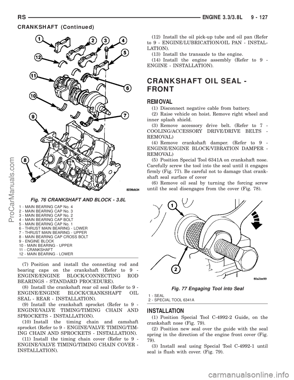
(7) Position and install the connecting rod and
bearing caps on the crankshaft (Refer to 9 -
ENGINE/ENGINE BLOCK/CONNECTING ROD
BEARINGS - STANDARD PROCEDURE).
(8) Install the crankshaft rear oil seal (Refer to 9 -
ENGINE/ENGINE BLOCK/CRANKSHAFT OIL
SEAL - REAR - INSTALLATION).
(9) Install the crankshaft sprocket (Refer to 9 -
ENGINE/VALVE TIMING/TIMING CHAIN AND
SPROCKETS - INSTALLATION).
(10) Install the timing chain and camshaft
sprocket (Refer to 9 - ENGINE/VALVE TIMING/TIM-
ING CHAIN AND SPROCKETS - INSTALLATION).
(11) Install the timing chain cover (Refer to 9 -
ENGINE/VALVE TIMING/TIMING CHAIN COVER -
INSTALLATION).(12) Install the oil pick-up tube and oil pan (Refer
to 9 - ENGINE/LUBRICATION/OIL PAN - INSTAL-
LATION).
(13) Install the transaxle to the engine.
(14) Install the engine assembly (Refer to 9 -
ENGINE - INSTALLATION).
CRANKSHAFT OIL SEAL -
FRONT
REMOVAL
(1) Disconnect negative cable from battery.
(2) Raise vehicle on hoist. Remove right wheel and
inner splash shield.
(3) Remove accessory drive belt. (Refer to 7 -
COOLING/ACCESSORY DRIVE/DRIVE BELTS -
REMOVAL)
(4) Remove crankshaft damper. (Refer to 9 -
ENGINE/ENGINE BLOCK/VIBRATION DAMPER -
REMOVAL)
(5) Position Special Tool 6341A on crankshaft nose.
Carefully screw the tool into the seal until it engages
firmly (Fig. 77). Be careful not to damage that crank-
shaft seal surface of cover
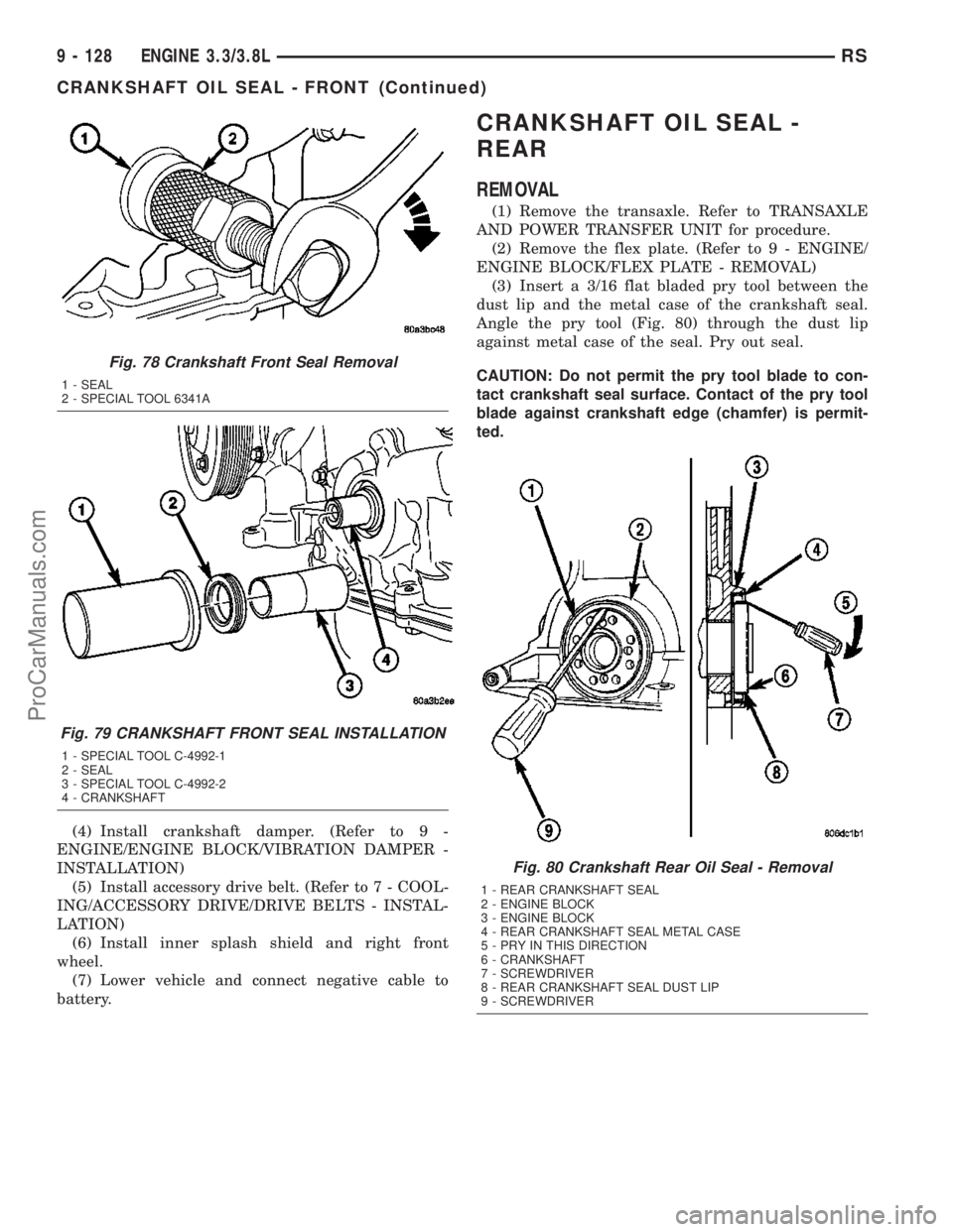
(6) Remove oil seal by turning the forcing screw
until the seal disengages from the cover (Fig. 78).
INSTALLATION
(1) Position Special Tool C-4992-2 Guide, on the
crankshaft nose (Fig. 79).
(2) Position new seal over the guide with the seal
spring in the direction of the engine front cover (Fig.
79).
(3) Install seal using Special Tool C-4992-1 until
seal is flush with cover. (Fig. 79).
Fig. 76 CRANKSHAFT AND BLOCK - 3.8L
1 - MAIN BEARING CAP No. 4
2 - MAIN BEARING CAP No. 3
3 - MAIN BEARING CAP No. 2
4 - MAIN BEARING CAP BOLT
5 - MAIN BEARING CAP No. 1
6 - THRUST MAIN BEARING - LOWER
7 - THRUST MAIN BEARING - UPPER
8 - MAIN BEARING CAP CROSS BOLT
9 - ENGINE BLOCK
10 - MAIN BEARING - UPPER
11 - CRANKSHAFT
12 - MAIN BEARING - LOWER
Fig. 77 Engaging Tool into Seal
1 - SEAL
2 - SPECIAL TOOL 6341A
RSENGINE 3.3/3.8L9 - 127
CRANKSHAFT (Continued)
ProCarManuals.com
Page 1307 of 2177
(4) Install crankshaft damper. (Refer to 9 -
ENGINE/ENGINE BLOCK/VIBRATION DAMPER -
INSTALLATION)
(5) Install accessory drive belt. (Refer to 7 - COOL-
ING/ACCESSORY DRIVE/DRIVE BELTS - INSTAL-
LATION)
(6) Install inner splash shield and right front
wheel.
(7) Lower vehicle and connect negative cable to
battery.
CRANKSHAFT OIL SEAL -
REAR
REMOVAL
(1) Remove the transaxle. Refer to TRANSAXLE
AND POWER TRANSFER UNIT for procedure.
(2) Remove the flex plate. (Refer to 9 - ENGINE/
ENGINE BLOCK/FLEX PLATE - REMOVAL)
(3) Insert a 3/16 flat bladed pry tool between the
dust lip and the metal case of the crankshaft seal.
Angle the pry tool (Fig. 80) through the dust lip
against metal case of the seal. Pry out seal.
CAUTION: Do not permit the pry tool blade to con-
tact crankshaft seal surface. Contact of the pry tool
blade against crankshaft edge (chamfer) is permit-
ted.
Fig. 78 Crankshaft Front Seal Removal
1 - SEAL
2 - SPECIAL TOOL 6341A
Fig. 79 CRANKSHAFT FRONT SEAL INSTALLATION
1 - SPECIAL TOOL C-4992-1
2 - SEAL
3 - SPECIAL TOOL C-4992-2
4 - CRANKSHAFT
Fig. 80 Crankshaft Rear Oil Seal - Removal
1 - REAR CRANKSHAFT SEAL
2 - ENGINE BLOCK
3 - ENGINE BLOCK
4 - REAR CRANKSHAFT SEAL METAL CASE
5 - PRY IN THIS DIRECTION
6 - CRANKSHAFT
7 - SCREWDRIVER
8 - REAR CRANKSHAFT SEAL DUST LIP
9 - SCREWDRIVER
9 - 128 ENGINE 3.3/3.8LRS
CRANKSHAFT OIL SEAL - FRONT (Continued)
ProCarManuals.com