2003 CHRYSLER CARAVAN sensor
[x] Cancel search: sensorPage 1125 of 2177
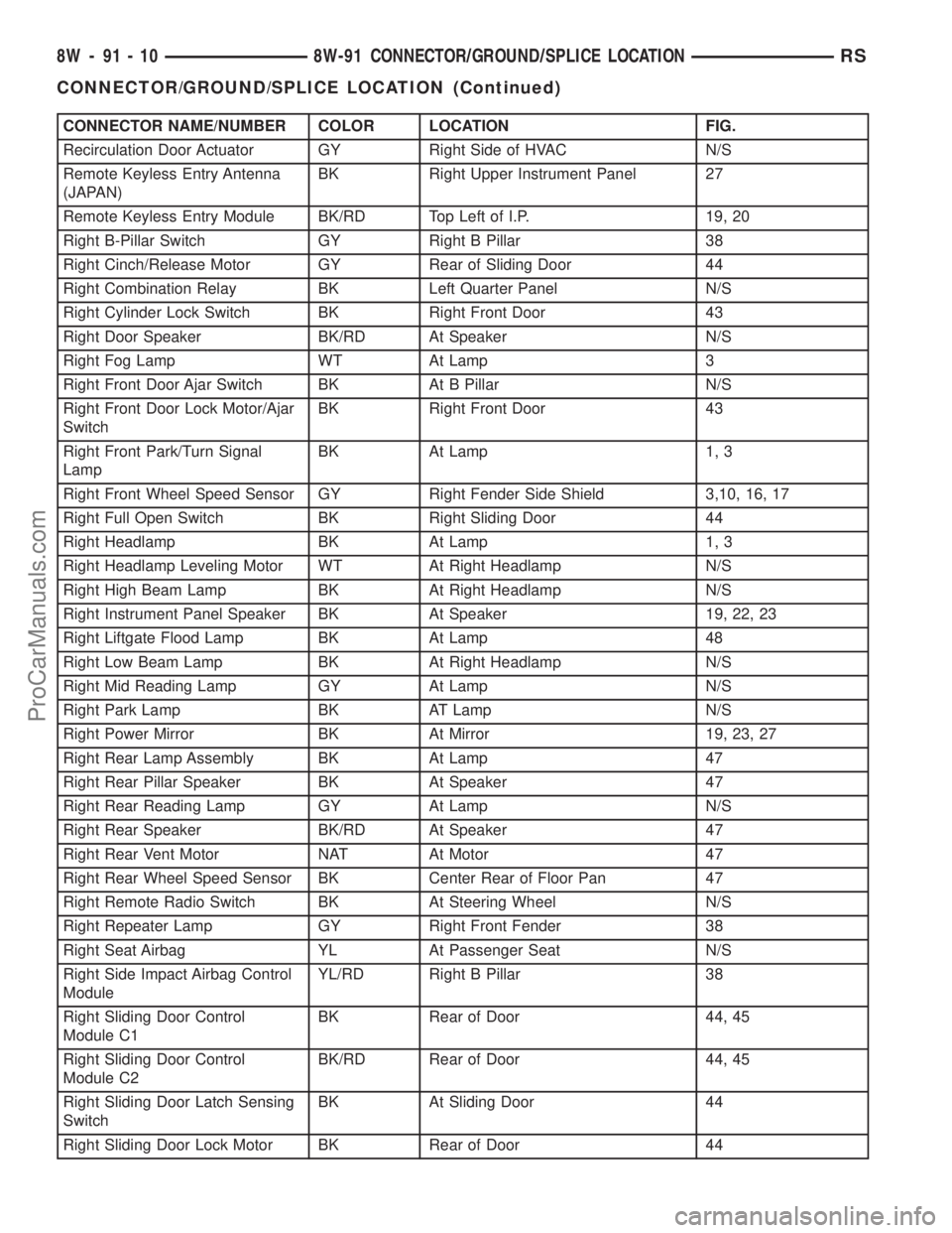
CONNECTOR NAME/NUMBER COLOR LOCATION FIG.
Recirculation Door Actuator GY Right Side of HVAC N/S
Remote Keyless Entry Antenna
(JAPAN)BK Right Upper Instrument Panel 27
Remote Keyless Entry Module BK/RD Top Left of I.P. 19, 20
Right B-Pillar Switch GY Right B Pillar 38
Right Cinch/Release Motor GY Rear of Sliding Door 44
Right Combination Relay BK Left Quarter Panel N/S
Right Cylinder Lock Switch BK Right Front Door 43
Right Door Speaker BK/RD At Speaker N/S
Right Fog Lamp WT At Lamp 3
Right Front Door Ajar Switch BK At B Pillar N/S
Right Front Door Lock Motor/Ajar
SwitchBK Right Front Door 43
Right Front Park/Turn Signal
LampBK At Lamp 1, 3
Right Front Wheel Speed Sensor GY Right Fender Side Shield 3,10, 16, 17
Right Full Open Switch BK Right Sliding Door 44
Right Headlamp BK At Lamp 1, 3
Right Headlamp Leveling Motor WT At Right Headlamp N/S
Right High Beam Lamp BK At Right Headlamp N/S
Right Instrument Panel Speaker BK At Speaker 19, 22, 23
Right Liftgate Flood Lamp BK At Lamp 48
Right Low Beam Lamp BK At Right Headlamp N/S
Right Mid Reading Lamp GY At Lamp N/S
Right Park Lamp BK AT Lamp N/S
Right Power Mirror BK At Mirror 19, 23, 27
Right Rear Lamp Assembly BK At Lamp 47
Right Rear Pillar Speaker BK At Speaker 47
Right Rear Reading Lamp GY At Lamp N/S
Right Rear Speaker BK/RD At Speaker 47
Right Rear Vent Motor NAT At Motor 47
Right Rear Wheel Speed Sensor BK Center Rear of Floor Pan 47
Right Remote Radio Switch BK At Steering Wheel N/S
Right Repeater Lamp GY Right Front Fender 38
Right Seat Airbag YL At Passenger Seat N/S
Right Side Impact Airbag Control
ModuleYL/RD Right B Pillar 38
Right Sliding Door Control
Module C1BK Rear of Door 44, 45
Right Sliding Door Control
Module C2BK/RD Rear of Door 44, 45
Right Sliding Door Latch Sensing
SwitchBK At Sliding Door 44
Right Sliding Door Lock Motor BK Rear of Door 44
8W - 91 - 10 8W-91 CONNECTOR/GROUND/SPLICE LOCATIONRS
CONNECTOR/GROUND/SPLICE LOCATION (Continued)
ProCarManuals.com
Page 1126 of 2177
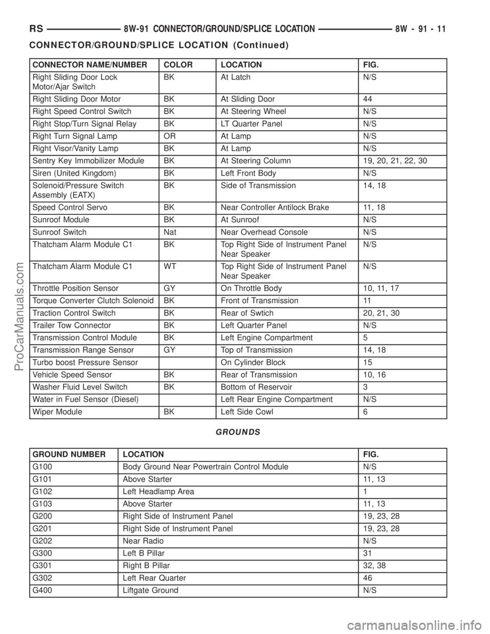
CONNECTOR NAME/NUMBER COLOR LOCATION FIG.
Right Sliding Door Lock
Motor/Ajar SwitchBK At Latch N/S
Right Sliding Door Motor BK At Sliding Door 44
Right Speed Control Switch BK At Steering Wheel N/S
Right Stop/Turn Signal Relay BK LT Quarter Panel N/S
Right Turn Signal Lamp OR At Lamp N/S
Right Visor/Vanity Lamp BK At Lamp N/S
Sentry Key Immobilizer Module BK At Steering Column 19, 20, 21, 22, 30
Siren (United Kingdom) BK Left Front Body N/S
Solenoid/Pressure Switch
Assembly (EATX)BK Side of Transmission 14, 18
Speed Control Servo BK Near Controller Antilock Brake 11, 18
Sunroof Module BK At Sunroof N/S
Sunroof Switch Nat Near Overhead Console N/S
Thatcham Alarm Module C1 BK Top Right Side of Instrument Panel
Near SpeakerN/S
Thatcham Alarm Module C1 WT Top Right Side of Instrument Panel
Near SpeakerN/S
Throttle Position Sensor GY On Throttle Body 10, 11, 17
Torque Converter Clutch Solenoid BK Front of Transmission 11
Traction Control Switch BK Rear of Swtich 20, 21, 30
Trailer Tow Connector BK Left Quarter Panel N/S
Transmission Control Module BK Left Engine Compartment 5
Transmission Range Sensor GY Top of Transmission 14, 18
Turbo boost Pressure Sensor On Cylinder Block 15
Vehicle Speed Sensor BK Rear of Transmission 10, 16
Washer Fluid Level Switch BK Bottom of Reservoir 3
Water in Fuel Sensor (Diesel) Left Rear Engine Compartment N/S
Wiper Module BK Left Side Cowl 6
GROUNDS
GROUND NUMBER LOCATION FIG.
G100 Body Ground Near Powertrain Control Module N/S
G101 Above Starter 11, 13
G102 Left Headlamp Area 1
G103 Above Starter 11, 13
G200 Right Side of Instrument Panel 19, 23, 28
G201 Right Side of Instrument Panel 19, 23, 28
G202 Near Radio N/S
G300 Left B Pillar 31
G301 Right B Pillar 32, 38
G302 Left Rear Quarter 46
G400 Liftgate Ground N/S
RS8W-91 CONNECTOR/GROUND/SPLICE LOCATION8W-91-11
CONNECTOR/GROUND/SPLICE LOCATION (Continued)
ProCarManuals.com
Page 1127 of 2177
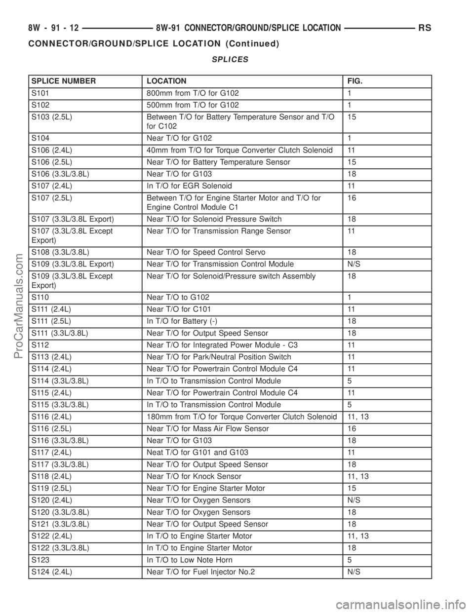
SPLICES
SPLICE NUMBER LOCATION FIG.
S101 800mm from T/O for G102 1
S102 500mm from T/O for G102 1
S103 (2.5L) Between T/O for Battery Temperature Sensor and T/O
for C10215
S104 Near T/O for G102 1
S106 (2.4L) 40mm from T/O for Torque Converter Clutch Solenoid 11
S106 (2.5L) Near T/O for Battery Temperature Sensor 15
S106 (3.3L/3.8L) Near T/O for G103 18
S107 (2.4L) In T/O for EGR Solenoid 11
S107 (2.5L) Between T/O for Engine Starter Motor and T/O for
Engine Control Module C116
S107 (3.3L/3.8L Export) Near T/O for Solenoid Pressure Switch 18
S107 (3.3L/3.8L Except
Export)Near T/O for Transmission Range Sensor 11
S108 (3.3L/3.8L) Near T/O for Speed Control Servo 18
S109 (3.3L/3.8L Export) Near T/O for Transmission Control Module N/S
S109 (3.3L/3.8L Except
Export)Near T/O for Solenoid/Pressure switch Assembly 18
S110 Near T/O to G102 1
S111 (2.4L) Near T/O for C101 11
S111 (2.5L) In T/O for Battery (-) 18
S111 (3.3L/3.8L) Near T/O for Output Speed Sensor 18
S112 Near T/O for Integrated Power Module - C3 11
S113 (2.4L) Near T/O for Park/Neutral Position Switch 11
S114 (2.4L) Near T/O for Powertrain Control Module C4 11
S114 (3.3L/3.8L) In T/O to Transmission Control Module 5
S115 (2.4L) Near T/O for Powertrain Control Module C4 11
S115 (3.3L/3.8L) In T/O to Transmission Control Module 5
S116 (2.4L) 180mm from T/O for Torque Converter Clutch Solenoid 11, 13
S116 (2.5L) Near T/O for Mass Air Flow Sensor 16
S116 (3.3L/3.8L) Near T/O for G103 18
S117 (2.4L) Neat T/O for G101 and G103 11
S117 (3.3L/3.8L) Near T/O for Output Speed Sensor 18
S118 (2.4L) Near T/O for Knock Sensor 11, 13
S119 (2.5L) Near T/O for Engine Starter Motor 15
S120 (2.4L) Near T/O for Oxygen Sensors N/S
S120 (3.3L/3.8L) Near T/O for Oxygen Sensors 18
S121 (3.3L/3.8L) Near T/O for Output Speed Sensor 18
S122 (2.4L) In T/O to Engine Starter Motor 11, 13
S122 (3.3L/3.8L) In T/O to Engine Starter Motor 18
S123 In T/O to Low Note Horn 5
S124 (2.4L) Near T/O for Fuel Injector No.2 N/S
8W - 91 - 12 8W-91 CONNECTOR/GROUND/SPLICE LOCATIONRS
CONNECTOR/GROUND/SPLICE LOCATION (Continued)
ProCarManuals.com
Page 1128 of 2177

SPLICE NUMBER LOCATION FIG.
S124 (3.3L/3.8L) Near T/O for Fuel Injector No.5 and No.6 N/S
S125 (2.4L) In T/O for Manifold Absolute Pressure Sensor N/S
S126 In Right Headlamp Leveling Assembly N/S
S127 (2.5L) In T/O for Engine Starter Motor N/S
S128 (2.5L) Near T/O for Engine Starter Motor 15
S129 (2.5L) Near T/O for Battery (+) N/S
S130 (2.5L) Near T/O for Battery (+) N/S
S131 Near T/O for Transmission Control Module 11
S131 (3.3L/3.8L) Near T/O for Transmission Control Module N/S
S132 (2.5L) Near T/O for Battery (+) N/S
S133 (2.4L) Near T/O for Integrated Power Module C3 11
S134 (2.5L) IN T/O for Engine Control Module 15
S135 (2.5L) Near T/O for Glow Plug No.2 15
S136 (2.5L) In T/O for Radiator Fan Relays 2
S137 (2.5L) Near T/O for A/C Compressor Clutch 15
S138 (2.5L) Between T/O for Radiator Fan No.2 and T/O for G102 1
S139 (2.5L) Between T/O for Engine Starter Motor and T/O for
Engine Control Module C116
S141 (2.4L) Near T/O for Battery(-) 11
S141 (2.5L) Near T/O for G100 N/S
S141 (3.3L/3.8L) Near T/O for Powertrain Control Module N/S
S142 (3.3L/3.8L) Near T/O for A/C Compressor Clutch 18
S143 (2.5L) Near T/O for Engine Control Module C1 15
S143 (3.3L/3.8L) Near T/O for Integrated Power Module - C3 N/S
S144 (2.5L) Between T/O for Battery Temperature Sensor and T/O
for C10315
S148 (2.5L) Near T/O for Engine Starter Motor 15
S149 (3.3L/3.8L) Near T/O for Transmission Control Module 5
S150 (2.5L) Between T/O for Battery Temperature Sensor and T/O
for C10315
S151 (2.5L) Near T/O for Radiator Fan Relay No.1 2
S152 (2.5L) Near T/O for Radiator Fan No.1 1
S157 (2.5L) Near T/O for Glow Plug No.1 15
S177 In Right Headlamp Wiring Assembly N/S
S179 In Left Headlamp Wiring Assembly N/S
S187 (2.5L) In T/O for Engine Control Module C1 15
S188 (2.5L) Near T/O for Radiator Fan Relay No.1 2
S201 In T/O to Instrument Panel Speaker 19, 25
S202 Near T/O for Instrument Panel Switch Bank 19, 25
S203 Near T/O for Instrument Panel Switch Bank 19, 25
S204 Near T/O to Instrument Panel Speaker 19, 25
S205 Near T/O for C201 19
S206 Near T/O for Instrument Cluster 19
RS8W-91 CONNECTOR/GROUND/SPLICE LOCATION8W-91-13
CONNECTOR/GROUND/SPLICE LOCATION (Continued)
ProCarManuals.com
Page 1138 of 2177
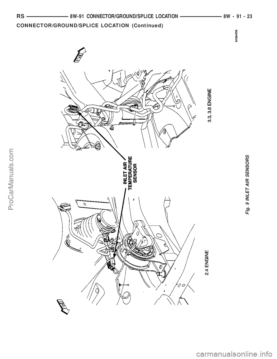
Fig. 9 INLET AIR SENSORS
RS8W-91 CONNECTOR/GROUND/SPLICE LOCATION8W-91-23
CONNECTOR/GROUND/SPLICE LOCATION (Continued)
ProCarManuals.com
Page 1141 of 2177
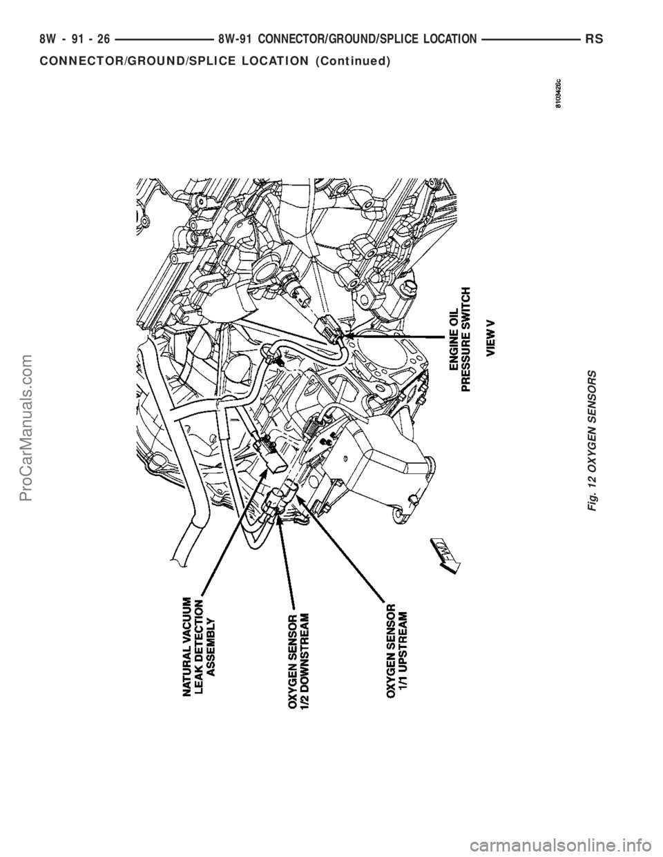
Fig. 12 OXYGEN SENSORS
8W - 91 - 26 8W-91 CONNECTOR/GROUND/SPLICE LOCATIONRS
CONNECTOR/GROUND/SPLICE LOCATION (Continued)
ProCarManuals.com
Page 1186 of 2177
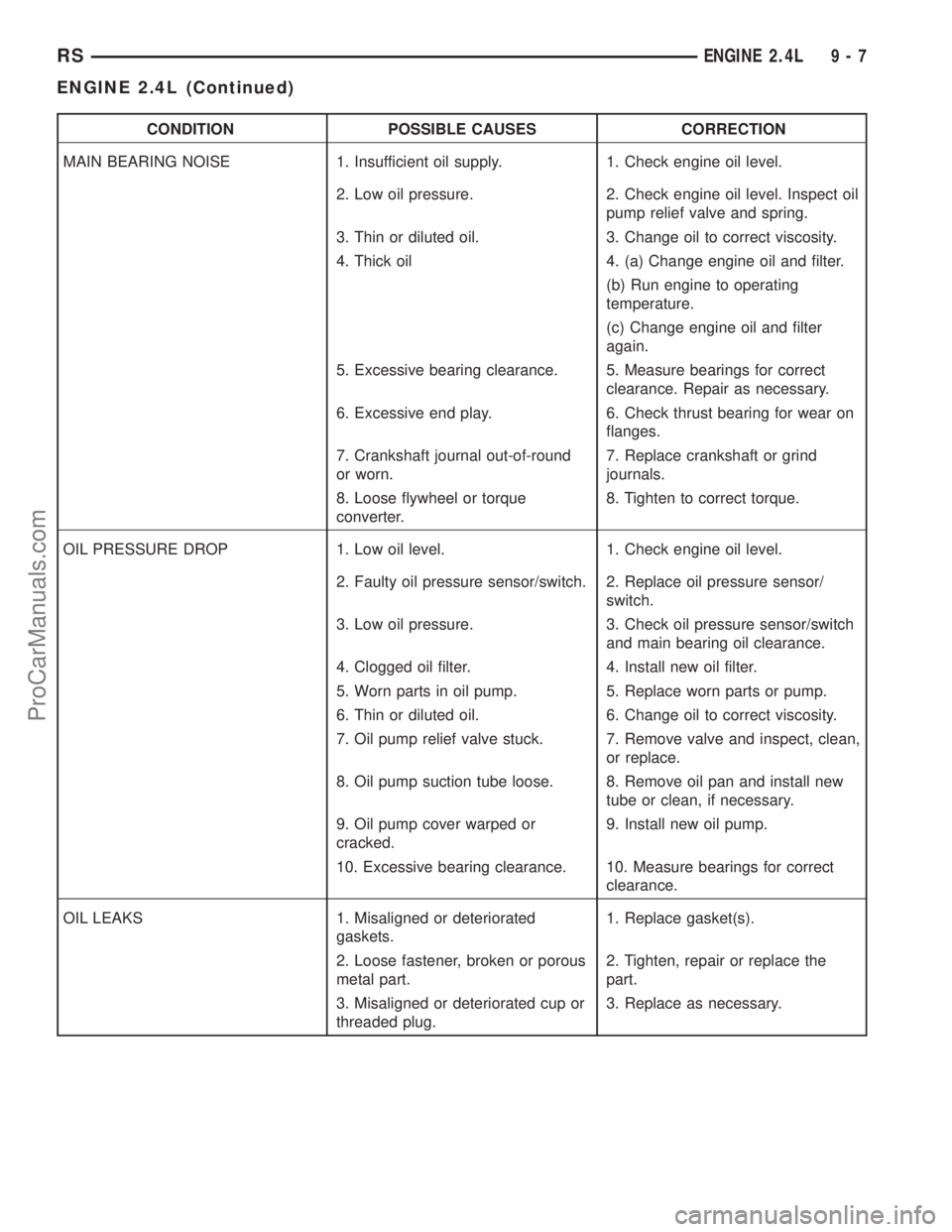
CONDITION POSSIBLE CAUSES CORRECTION
MAIN BEARING NOISE 1. Insufficient oil supply. 1. Check engine oil level.
2. Low oil pressure. 2. Check engine oil level. Inspect oil
pump relief valve and spring.
3. Thin or diluted oil. 3. Change oil to correct viscosity.
4. Thick oil 4. (a) Change engine oil and filter.
(b) Run engine to operating
temperature.
(c) Change engine oil and filter
again.
5. Excessive bearing clearance. 5. Measure bearings for correct
clearance. Repair as necessary.
6. Excessive end play. 6. Check thrust bearing for wear on
flanges.
7. Crankshaft journal out-of-round
or worn.7. Replace crankshaft or grind
journals.
8. Loose flywheel or torque
converter.8. Tighten to correct torque.
OIL PRESSURE DROP 1. Low oil level. 1. Check engine oil level.
2. Faulty oil pressure sensor/switch. 2. Replace oil pressure sensor/
switch.
3. Low oil pressure. 3. Check oil pressure sensor/switch
and main bearing oil clearance.
4. Clogged oil filter. 4. Install new oil filter.
5. Worn parts in oil pump. 5. Replace worn parts or pump.
6. Thin or diluted oil. 6. Change oil to correct viscosity.
7. Oil pump relief valve stuck. 7. Remove valve and inspect, clean,
or replace.
8. Oil pump suction tube loose. 8. Remove oil pan and install new
tube or clean, if necessary.
9. Oil pump cover warped or
cracked.9. Install new oil pump.
10. Excessive bearing clearance. 10. Measure bearings for correct
clearance.
OIL LEAKS 1. Misaligned or deteriorated
gaskets.1. Replace gasket(s).
2. Loose fastener, broken or porous
metal part.2. Tighten, repair or replace the
part.
3. Misaligned or deteriorated cup or
threaded plug.3. Replace as necessary.
RSENGINE 2.4L9-7
ENGINE 2.4L (Continued)
ProCarManuals.com
Page 1203 of 2177
AIR CLEANER ELEMENT
REMOVAL
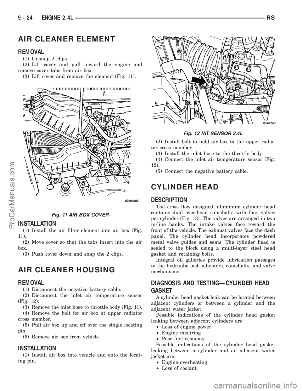
(1) Unsnap 2 clips.
(2) Lift cover and pull toward the engine and
remove cover tabs from air box.
(3) Lift cover and remove the element (Fig. 11).
INSTALLATION
(1) Install the air filter element into air box (Fig.
11).
(2) Move cover so that the tabs insert into the air
box.
(3) Push cover down and snap the 2 clips.
AIR CLEANER HOUSING
REMOVAL
(1) Disconnect the negative battery cable.
(2) Disconnect the inlet air temperature sensor
(Fig. 12).
(3) Remove the inlet hose to throttle body (Fig. 11).
(4) Remove the bolt for air box at upper radiator
cross member.
(5) Pull air box up and off over the single locating
pin.
(6) Remove air box from vehicle
INSTALLATION
(1) Install air box into vehicle and onto the locat-
ing pin.(2) Install bolt to hold air box to the upper radia-
tor cross member.
(3) Install the inlet hose to the throttle body.
(4) Connect the inlet air temperature sensor (Fig.
12).
(5) Connect the negative battery cable.
CYLINDER HEAD
DESCRIPTION
The cross flow designed, aluminum cylinder head
contains dual over-head camshafts with four valves
per cylinder (Fig. 13). The valves are arranged in two
in-line banks. The intake valves face toward the
front of the vehicle. The exhaust valves face the dash
panel. The cylinder head incorporates powdered
metal valve guides and seats. The cylinder head is
sealed to the block using a multi-layer steel head
gasket and retaining bolts.
Integral oil galleries provide lubrication passages
to the hydraulic lash adjusters, camshafts, and valve
mechanisms.
DIAGNOSIS AND TESTINGÐCYLINDER HEAD
GASKET
A cylinder head gasket leak can be located between
adjacent cylinders or between a cylinder and the
adjacent water jacket.
Possible indications of the cylinder head gasket
leaking between adjacent cylinders are:
²Loss of engine power
²Engine misfiring
²Poor fuel economy
Possible indications of the cylinder head gasket
leaking between a cylinder and an adjacent water
jacket are:
²Engine overheating
²Loss of coolant
Fig. 11 AIR BOX COVER
Fig. 12 IAT SENSOR 2.4L
9 - 24 ENGINE 2.4LRS
ProCarManuals.com