2003 CHRYSLER CARAVAN light
[x] Cancel search: lightPage 1739 of 2177
PANEL SECTIONING
If it is required to section a large panel for a plas-
tic repair, it will be necessary to reinforce the panel
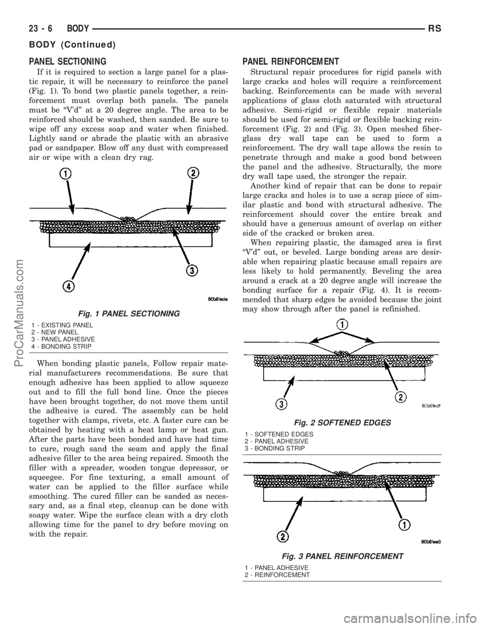
(Fig. 1). To bond two plastic panels together, a rein-
forcement must overlap both panels. The panels
must be ªV'dº at a 20 degree angle. The area to be
reinforced should be washed, then sanded. Be sure to
wipe off any excess soap and water when finished.
Lightly sand or abrade the plastic with an abrasive
pad or sandpaper. Blow off any dust with compressed
air or wipe with a clean dry rag.
When bonding plastic panels, Follow repair mate-
rial manufacturers recommendations. Be sure that
enough adhesive has been applied to allow squeeze
out and to fill the full bond line. Once the pieces
have been brought together, do not move them until
the adhesive is cured. The assembly can be held
together with clamps, rivets, etc. A faster cure can be
obtained by heating with a heat lamp or heat gun.
After the parts have been bonded and have had time
to cure, rough sand the seam and apply the final
adhesive filler to the area being repaired. Smooth the
filler with a spreader, wooden tongue depressor, or
squeegee. For fine texturing, a small amount of
water can be applied to the filler surface while
smoothing. The cured filler can be sanded as neces-
sary and, as a final step, cleanup can be done with
soapy water. Wipe the surface clean with a dry cloth
allowing time for the panel to dry before moving on
with the repair.
PANEL REINFORCEMENT
Structural repair procedures for rigid panels with
large cracks and holes will require a reinforcement
backing. Reinforcements can be made with several
applications of glass cloth saturated with structural
adhesive. Semi-rigid or flexible repair materials
should be used for semi-rigid or flexible backing rein-
forcement (Fig. 2) and (Fig. 3). Open meshed fiber-
glass dry wall tape can be used to form a
reinforcement. The dry wall tape allows the resin to
penetrate through and make a good bond between
the panel and the adhesive. Structurally, the more
dry wall tape used, the stronger the repair.
Another kind of repair that can be done to repair
large cracks and holes is to use a scrap piece of sim-
ilar plastic and bond with structural adhesive. The
reinforcement should cover the entire break and
should have a generous amount of overlap on either
side of the cracked or broken area.
When repairing plastic, the damaged area is first
ªV'dº out, or beveled. Large bonding areas are desir-
able when repairing plastic because small repairs are
less likely to hold permanently. Beveling the area
around a crack at a 20 degree angle will increase the
bonding surface for a repair (Fig. 4). It is recom-
mended that sharp edges be avoided because the joint
may show through after the panel is refinished.
Fig. 1 PANEL SECTIONING
1 - EXISTING PANEL
2 - NEW PANEL
3 - PANEL ADHESIVE
4 - BONDING STRIP
Fig. 2 SOFTENED EDGES
1 - SOFTENED EDGES
2 - PANEL ADHESIVE
3 - BONDING STRIP
Fig. 3 PANEL REINFORCEMENT
1 - PANEL ADHESIVE
2 - REINFORCEMENT
23 - 6 BODYRS
BODY (Continued)
ProCarManuals.com
Page 1772 of 2177
DECKLID/HATCH/LIFTGATE/TAILGATE
TABLE OF CONTENTS
page page
EXTERIOR HANDLE
REMOVAL.............................39
INSTALLATION.........................39
HINGE
REMOVAL.............................39
INSTALLATION.........................39
LATCH
REMOVAL.............................40
INSTALLATION.........................40
LATCH STRIKER
REMOVAL.............................40
INSTALLATION.........................40
LIFTGATE
REMOVAL.............................41
INSTALLATION.........................41
LIFTGATE SPOILER
REMOVAL.............................41INSTALLATION.........................41
LOCK CYLINDER
REMOVAL.............................41
INSTALLATION.........................41
SUPPORT CYLINDER
REMOVAL.............................42
INSTALLATION.........................42
TRIM PANEL
REMOVAL.............................42
INSTALLATION.........................43
SLAM BUMPER
REMOVAL
REMOVAL...........................43
REMOVAL - LIFTGATE SIDE.............43
INSTALLATION
INSTALLATION.......................43
INSTALLATION - LIFTGATE SIDE.........43
EXTERIOR HANDLE
REMOVAL
(1) Remove liftgate trim panel. (Refer to 23 -
BODY/DECKLID/HATCH/LIFTGATE/TAILGATE/
TRIM PANEL - REMOVAL)
(2) Disconnect the exterior handle electrical con-
nectors.
(3) Remove the two outer screws and the two inner
screws.
(4) Remove the exterior handle/license plate light
assembly.
INSTALLATION
(1) Route the exterior handle electrical connector
through the door and position handle.
(2) Install the two out screws and tighten to 20
N´m (15 ft. lbs.).
(3) Install the two inner bolts and tighten to 40
N´m (30 ft. lbs.).
(4) Connect the electrical connector.
(5) Install the trim panel. (Refer to 23 - BODY/
DECKLID/HATCH/LIFTGATE/TAILGATE/TRIM
PANEL - INSTALLATION)
HINGE
REMOVAL
(1) Release liftgate latch and open liftgate.
(2) Support liftgate on a suitable lifting device in
the full open position.
(3) Apply several layers of duct tape on the outside
of to roof across the gap to the lift gate to hold the
liftgate in position.
(4) Remove bolts attaching liftgate hinge to roof
header.
(5) Disconnect VTSS switch from the body har-
ness.
(6) Remove bolts attaching hinge to liftgate (Fig.
1).
(7) Remove hinge from vehicle.
INSTALLATION
(1) If necessary, paint replacement hinge before
installation.
(2) Place hinge in position on vehicle.
(3) Align hinge to marks on liftgate.
(4) Install bolts attaching hinge to liftgate (Fig. 1).
Tighten bolts to 33 N´m (24 ft. lbs.) torque.
(5) Align hinge to marks on roof header.
(6) Install bolts attaching liftgate hinge to roof
header. Tighten outer two bolts to 33 N´m (24 ft. lbs.)
torque. The sheet medal screw at center 12 N´m (105
in. lbs.)
(7) Remove duct tape from roof and liftgate.
RSDECKLID/HATCH/LIFTGATE/TAILGATE23-39
ProCarManuals.com
Page 1784 of 2177
FRONT FENDER
REMOVAL
(1) Remove headlamp housing. (Refer to 8 - ELEC-
TRICAL/LAMPS/LIGHTING - EXTERIOR/HEAD-
LAMP UNIT - REMOVAL)
(2) Remove mud guard.
(3) Remove inner splash shield.
(4) Remove fender to fascia nuts.
(5) Remove outboard cowl grille/fender bracket
screw.
(6) Remove fender bolt to lower rocker panel.
(7) Remove fender bolt to lower cowl.
(8) Pull fascia away from fender.
(9) Remove bolts attaching fender to upper rail.
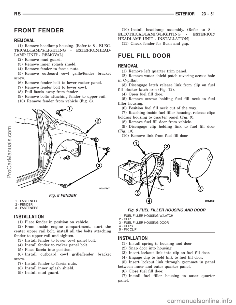
(10) Remove fender from vehicle (Fig. 8).
INSTALLATION
(1) Place fender in position on vehicle.
(2) From inside engine compartment, start the
center upper rail bolt. install all the bolts attaching
fender to upper rail and tighten.
(3) Install fender to lower cowl panel bolt.
(4) Install fender to rocker panel bolt.
(5) Place fascia into position.
(6) Install outboard cowl grille/fender bracket
screw.
(7) Install fender to fascia nuts.
(8) Install inner splash shield.
(9) Install mud guard.(10) Install headlamp assembly. (Refer to 8 -
ELECTRICAL/LAMPS/LIGHTING - EXTERIOR/
HEADLAMP UNIT - INSTALLATION)
(11) Check fender for flush and gap.
FUEL FILL DOOR
REMOVAL
(1) Remove left quarter trim panel.
(2) Remove water shield patch covering access hole
in C-pillar.
(3) Disengage latch release link from clip on fuel
fill blocker latch arm (Fig. 12).
(4) Open fuel fill door.
(5) Remove screws holding fuel fill neck to fuel
filler housing.
(6) Position fuel fill neck out of the way.
(7) Reaching inside fuel filler housing, release clips
holding housing to quarter panel (Fig. 9).
(8) Remove fuel fill door from vehicle.
(9) Disengage clip holding link to fuel fill door
(Fig. 13).
(10) Remove link from fuel fill door.
INSTALLATION
(1) Install spring to housing and door
(2) Snap door into housing.
(3) Insert lockout link into clip on fuel fill door.
(4) Engage clip to hold link to fuel fill door.
(5) Insert lockout link through grommet in panel
between inner and outer quarter panel.
(6) Close fuel fill door.
(7) Install fuel filler housing to outer quarter
panel.
Fig. 8 FENDER
1 - FASTENERS
2 - FENDER
3 - FASTENERS
Fig. 9 FUEL FILLER HOUSING AND DOOR
1 - FUEL FILLER HOUSING W/LATCH
2 - CLIP
3 - FUEL FILLER HOUSING DOOR
4 - CLIPS
5 - FIX CLIP
RSEXTERIOR23-51
ProCarManuals.com
Page 1803 of 2177

INSTRUMENT PANEL TOP PAD
ASSEMBLY
REMOVAL
(1) Remove the instrument cluster (Fig. 14). (Refer
to 8 - ELECTRICAL/INSTRUMENT CLUSTER -
REMOVAL)
(2) Remove the message center (Fig. 14). (Refer to
8 - ELECTRICAL/MESSAGE CENTER - REMOVAL)
(3) Remove the radio (Fig. 14). (Refer to 8 - ELEC-
TRICAL/AUDIO/RADIO - REMOVAL)
(4) Remove the headlamp switch (Fig. 14). (Refer
to 8 - ELECTRICAL/LAMPS/LIGHTING - EXTERI-
OR/HEADLAMP SWITCH - REMOVAL)
(5) Remove the lower console (Fig. 14). (Refer to 23
- BODY/INSTRUMENT PANEL/LOWER CONSOLE
- REMOVAL)
(6) Remove the lower panel. (Refer to 23 - BODY/
INSTRUMENT PANEL/LOWER INSTRUMENT
PANEL TRIM - REMOVAL)
(7) Remove the instrument panel assembly. (Refer
to 23 - BODY/INSTRUMENT PANEL/INSTRUMENT
PANEL ASSEMBLY - REMOVAL)
(8) Remove the instrument panel speakers.
(9) Remove the glove box light.
(10) Remove the two passenger air bag mounting
bolts (Fig. 15).
(11) Loosen the three passenger air bag support
bracket bolts to the hydro-form rail (Fig. 15).
(12) Remove the 16 screws along the upper edge of
the pad & panel assembly.
(13) Remove the 19 screws along the lower edge of
the pad & panel assembly.
(14) Remove the pad and panel assembly (Fig. 14).
INSTALLATION
(1) Position the pad & panel assembly onto the
instrument panel support structure.
Fig. 13 OVER STEERING COLUMN COVER
1 - INSTRUMENT PANEL OVER STEERING COLUMN COVER
2 - INSTRUMENT PANEL
Fig. 14 INSTRUMENT PANEL ASSEMBLY
1 - INSTRUMENT CLUSTER
2 - MESSAGE CENTER
3 - TOP COVER
4 - PAD AND PANEL ASSEMBLY
5 - LOWER CONSOLE
6 - LOWER PANEL
7 - RADIO
8 - HEADLAMP SWITCH
Fig. 15 AIRBAG MOUNTING HARDWARE
1 - AIR BAG SCREWS (2)
2 - ELECTRICAL CONNECTOR
3 - AIR BAG SUPPORT BRACKET BOLTS (3)
4 - HYDRO-FORM INSTRUMENT PANEL SUPPORT RAIL
23 - 70 INSTRUMENT PANELRS
OVER STEERING COLUMN COVER (Continued)
ProCarManuals.com
Page 1804 of 2177
(2) Install the 19 screws along the lower edge of
the pad & panel assembly.
(3) Install the 16 screws along the upper edge of
the pad & panel assembly.
(4) Install and tighten the two passenger air bag
mounting screws.
(5) Tighten the three passenger air bag support
bracket bolts to the hydro-form tube.
(6) Install the glove box light.
(7) Install the instrument panel speakers.
(8) Install the instrument panel assembly. (Refer
to 23 - BODY/INSTRUMENT PANEL/INSTRUMENT
PANEL ASSEMBLY - INSTALLATION)
(9) Install the lower panel. (Refer to 23 - BODY/
INSTRUMENT PANEL/LOWER INSTRUMENT
PANEL TRIM - INSTALLATION)(10) Install the lower console. (Refer to 23 - BODY/
INSTRUMENT PANEL/LOWER CONSOLE -
INSTALLATION)
(11) Install the headlamp switch. (Refer to 8 -
ELECTRICAL/LAMPS/LIGHTING - EXTERIOR/
HEADLAMP SWITCH - INSTALLATION)
(12) Install the radio. (Refer to 8 - ELECTRICAL/
AUDIO/RADIO - INSTALLATION)
(13) Install the message center. (Refer to 8 -
ELECTRICAL/MESSAGE CENTER - INSTALLA-
TION)
(14) Install the instrument cluster. (Refer to 8 -
ELECTRICAL/INSTRUMENT CLUSTER - INSTAL-
LATION)
RSINSTRUMENT PANEL23-71
INSTRUMENT PANEL TOP PAD ASSEMBLY (Continued)
ProCarManuals.com
Page 1807 of 2177
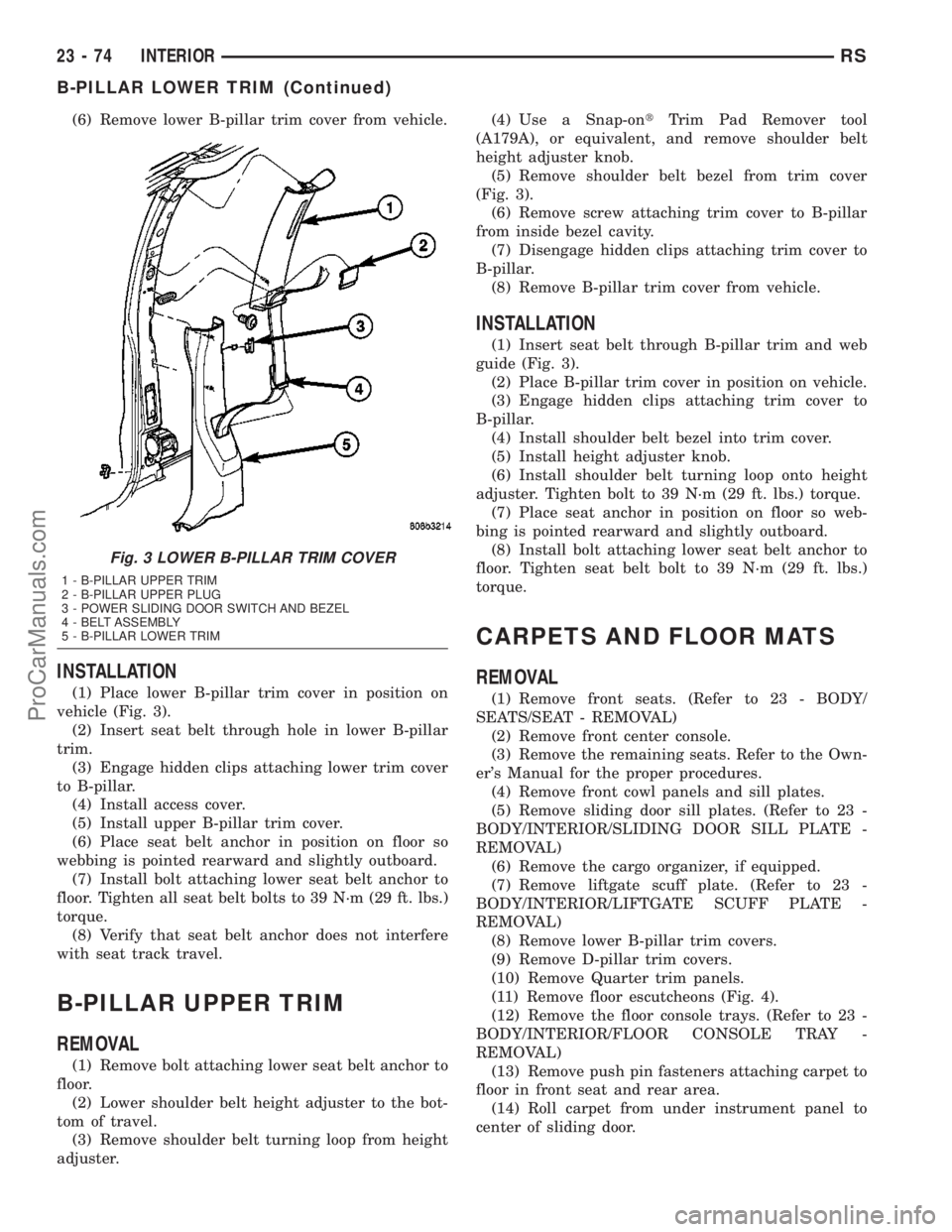
(6) Remove lower B-pillar trim cover from vehicle.
INSTALLATION
(1) Place lower B-pillar trim cover in position on
vehicle (Fig. 3).
(2) Insert seat belt through hole in lower B-pillar
trim.
(3) Engage hidden clips attaching lower trim cover
to B-pillar.
(4) Install access cover.
(5) Install upper B-pillar trim cover.
(6) Place seat belt anchor in position on floor so
webbing is pointed rearward and slightly outboard.
(7) Install bolt attaching lower seat belt anchor to
floor. Tighten all seat belt bolts to 39 N´m (29 ft. lbs.)
torque.
(8) Verify that seat belt anchor does not interfere
with seat track travel.
B-PILLAR UPPER TRIM
REMOVAL
(1) Remove bolt attaching lower seat belt anchor to
floor.
(2) Lower shoulder belt height adjuster to the bot-
tom of travel.
(3) Remove shoulder belt turning loop from height
adjuster.(4) Use a Snap-ontTrim Pad Remover tool
(A179A), or equivalent, and remove shoulder belt
height adjuster knob.
(5) Remove shoulder belt bezel from trim cover
(Fig. 3).
(6) Remove screw attaching trim cover to B-pillar
from inside bezel cavity.
(7) Disengage hidden clips attaching trim cover to
B-pillar.
(8) Remove B-pillar trim cover from vehicle.
INSTALLATION
(1) Insert seat belt through B-pillar trim and web
guide (Fig. 3).
(2) Place B-pillar trim cover in position on vehicle.
(3) Engage hidden clips attaching trim cover to
B-pillar.
(4) Install shoulder belt bezel into trim cover.
(5) Install height adjuster knob.
(6) Install shoulder belt turning loop onto height
adjuster. Tighten bolt to 39 N´m (29 ft. lbs.) torque.
(7) Place seat anchor in position on floor so web-
bing is pointed rearward and slightly outboard.
(8) Install bolt attaching lower seat belt anchor to
floor. Tighten seat belt bolt to 39 N´m (29 ft. lbs.)
torque.
CARPETS AND FLOOR MATS
REMOVAL
(1) Remove front seats. (Refer to 23 - BODY/
SEATS/SEAT - REMOVAL)
(2) Remove front center console.
(3) Remove the remaining seats. Refer to the Own-
er's Manual for the proper procedures.
(4) Remove front cowl panels and sill plates.
(5) Remove sliding door sill plates. (Refer to 23 -
BODY/INTERIOR/SLIDING DOOR SILL PLATE -
REMOVAL)
(6) Remove the cargo organizer, if equipped.
(7) Remove liftgate scuff plate. (Refer to 23 -
BODY/INTERIOR/LIFTGATE SCUFF PLATE -
REMOVAL)
(8) Remove lower B-pillar trim covers.
(9) Remove D-pillar trim covers.
(10) Remove Quarter trim panels.
(11) Remove floor escutcheons (Fig. 4).
(12) Remove the floor console trays. (Refer to 23 -
BODY/INTERIOR/FLOOR CONSOLE TRAY -
REMOVAL)
(13) Remove push pin fasteners attaching carpet to
floor in front seat and rear area.
(14) Roll carpet from under instrument panel to
center of sliding door.
Fig. 3 LOWER B-PILLAR TRIM COVER
1 - B-PILLAR UPPER TRIM
2 - B-PILLAR UPPER PLUG
3 - POWER SLIDING DOOR SWITCH AND BEZEL
4 - BELT ASSEMBLY
5 - B-PILLAR LOWER TRIM
23 - 74 INTERIORRS
B-PILLAR LOWER TRIM (Continued)
ProCarManuals.com
Page 1816 of 2177
PAINT
TABLE OF CONTENTS
page page
PAINT
SPECIFICATIONS - COLOR CODE CHARTS . . 83
BASE COAT/CLEARCOAT FINISH
DESCRIPTION.........................84
PAINT CODE
DESCRIPTION.........................84PAINTED TOUCH-UP
DESCRIPTION.........................84
FINESSE SANDING/BUFFING & POLISHING
DESCRIPTION.........................84
PAINT
SPECIFICATIONS - COLOR CODE CHARTS
EXTERIOR COLORS
EXTERIOR COLOR DAIMLERCHRYSLER
COLOR CODEEXTERIOR COLOR DAIMLERCHRYSLER
COLOR CODE
SATIN JADE PEARL
COATAP4 ONYX GREEN PEARL
COATYJR
BRIGHT SILVER
METALLIC CLEAR
COATWS2 PATRIOT BLUE
PEARL COATWB7
DARK GARNET RED
PEARL COATXRV BUTANE BLUE
METALLIC CLEAR
COATABE
INFERNO RED TINTED
PEARL COATWEL BRILLIANT BLACK
CRYSTAL PEARL
COATAXR
LIGHT ALMOND
PEARL METALLIC
CLEAR COATZKJ STONE WHITE CLEAR
COATSW1
INTERIOR COLORS
INTERIOR COLOR DAIMLERCHRYSLER
COLOR CODEINTERIOR COLOR DAIMLERCHRYSLER
COLOR CODE
NAVY BLUE B TAUPE T
SANDSTONE F
RSPAINT23-83
ProCarManuals.com
Page 1817 of 2177
BASE COAT/CLEARCOAT
FINISH
DESCRIPTION
On most vehicles a two-part paint application
(basecoat/clearcoat) is used. Color paint that is
applied to primer is called basecoat. The clearcoat
protects the basecoat from ultraviolet light and pro-
vides a durable high-gloss finish.
CAUTION: Do not use abrasive chemicals or com-
pounds on painted surfaces. Damage to finish can
result.
Do not use harsh alkaline based cleaning solvents
on painted surfaces. Damage to finish or color can
result.
PAINT CODE
DESCRIPTION
Exterior vehicle body colors are identified on the
Body Code plate. (Refer to VEHICLE DATA/VEHI-
CLE INFORMATION/BODY CODE PLATE -
DESCRIPTION). The paint code is also identified on
the Vehicle Safety Certification Label which is
located on the drivers door shut face. The first digit
of the paint code listed on the vehicle indicates the
sequence of application, i.e.: P = primary coat, Q =
secondary coat. The codes listed in the Color Code
Chart are used for manufacturing purposes.
PAINTED TOUCH-UP
DESCRIPTION
When a painted metal surface has been scratched
or chipped, it should be touched up as soon as possi-
ble to avoid corrosion. For best results, use Mopart
Scratch Filler/Primer, Touch Up Paints and Clear Top
Coat. (Refer to VEHICLE DATA/VEHICLE INFOR-
MATION/BODY CODE PLATE - DESCRIPTION).
WARNING: USE AN OSHA APPROVED RESPIRATOR
AND SAFETY GLASSES WHEN SPRAYING PAINT
OR SOLVENTS IN A CONFINED AREA. PERSONAL
INJURY CAN RESULT.
TOUCH UP PROCEDURE
(1) Scrape loose paint and corrosion from inside
scratch or chip.
(2) Clean affected area with MopartTar/Road Oil
Remover, and allow to dry.
(3) Fill the inside of the scratch or chip with a coat
of filler/primer. Do not overlap primer onto good sur-
face finish. The applicator brush should be wet
enough to puddle-fill the scratch or chip without run-
ning. Do not stroke brush applicator on body surface.
Allow the filler/primer to dry hard.
(4) Cover the filler/primer with color touch up
paint. Do not overlap touch up color onto the original
color coat around the scratch or chip. Butt the new
color to the original color, if possible. Do not stroke
applicator brush on body surface. Allow touch up
paint to dry hard.
(5) On vehicles without clearcoat, the touch up
color can be lightly finesse sanded (1500 grit) and
polished with rubbing compound.
(6) On vehicles with clearcoat, apply clear top coat
to touch up paint with the same technique as
described in Step 4. Allow clear top coat to dry hard.
If desired, Step 5 can be performed on clear top coat.
WARNING: AVOID PROLONGED SKIN CONTACT
WITH PETROLEUM OR ALCOHOL ± BASED CLEAN-
ING SOLVENTS. PERSONAL INJURY CAN RESULT.
FINESSE SANDING/BUFFING &
POLISHING
DESCRIPTION
Minor acid etching, orange peel, or smudging in
clearcoat or single-stage finishes can be reduced with
light finesse sanding, hand buffing, and polishing.If
the finish has been finesse sanded in the past,
it cannot be repeated. Finesse sanding opera-
tion should be performed by a trained automo-
tive paint technician.
CAUTION: Do not remove clearcoat finish, if
equipped. Basecoat paint must retain clearcoat for
durability.
23 - 84 PAINTRS
ProCarManuals.com