2003 CHRYSLER CARAVAN warning
[x] Cancel search: warningPage 2043 of 2177
REMOVAL
The blower motor and blower wheel are serviced
only as a balanced unit. If either component is faulty
or damaged, the entire unit must be replaced.
WARNING: REFER TO THE APPLICABLE WARN-
INGS AND CAUTIONS FOR THIS SYSTEM BEFORE
PERFORMING THE FOLLOWING OPERATION.
(Refer to 24 - HEATING & AIR CONDITIONING/
PLUMBING - FRONT - WARNING - A/C PLUMBING),
(Refer to 24 - HEATING & AIR CONDITIONING/
PLUMBING - FRONT - CAUTION - A/C PLUMBING),
and (Refer to 24 - HEATING & AIR CONDITIONING/
PLUMBING - FRONT - WARNING - HEATER PLUMB-
ING).
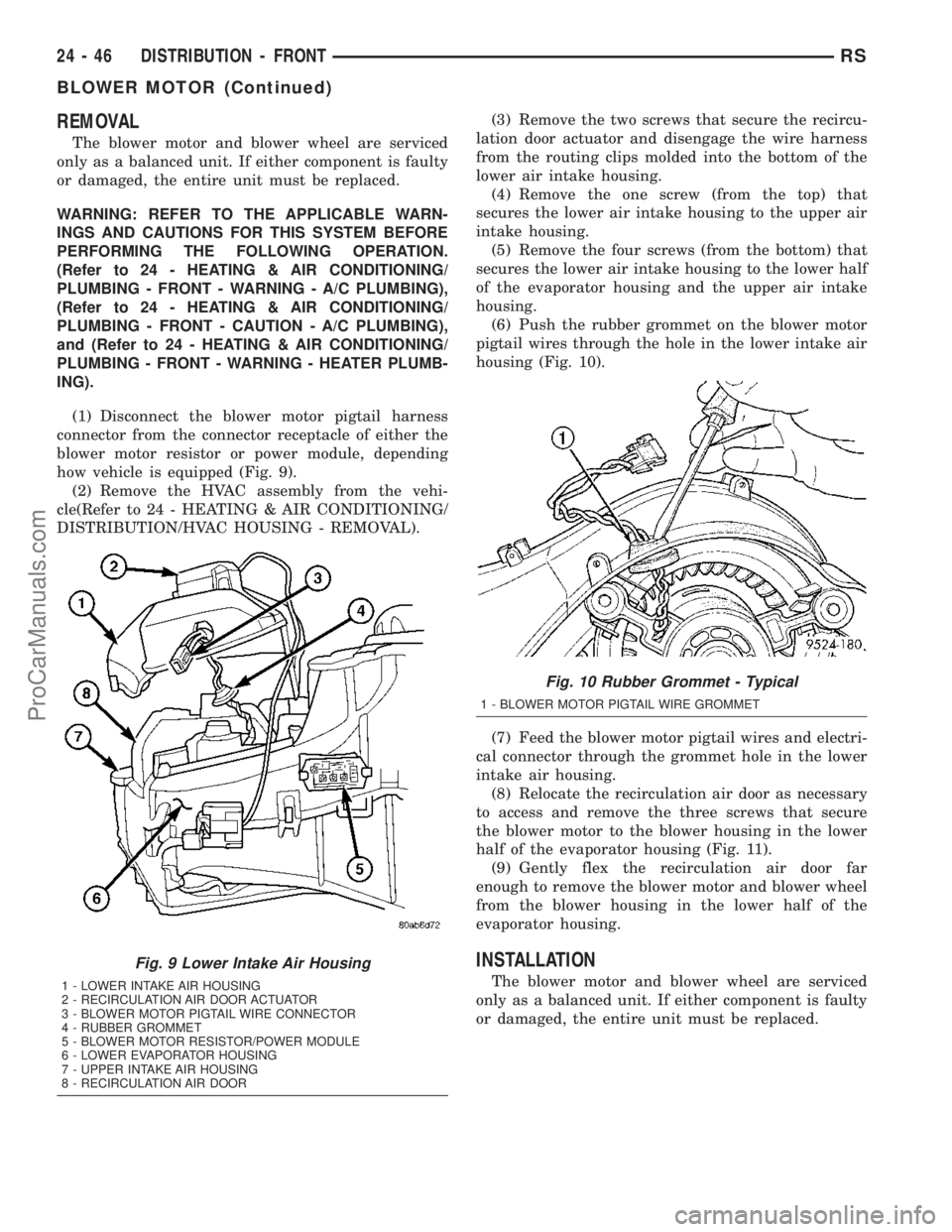
(1) Disconnect the blower motor pigtail harness
connector from the connector receptacle of either the
blower motor resistor or power module, depending
how vehicle is equipped (Fig. 9).
(2) Remove the HVAC assembly from the vehi-
cle(Refer to 24 - HEATING & AIR CONDITIONING/
DISTRIBUTION/HVAC HOUSING - REMOVAL).(3) Remove the two screws that secure the recircu-
lation door actuator and disengage the wire harness
from the routing clips molded into the bottom of the
lower air intake housing.
(4) Remove the one screw (from the top) that
secures the lower air intake housing to the upper air
intake housing.
(5) Remove the four screws (from the bottom) that
secures the lower air intake housing to the lower half
of the evaporator housing and the upper air intake
housing.
(6) Push the rubber grommet on the blower motor
pigtail wires through the hole in the lower intake air
housing (Fig. 10).
(7) Feed the blower motor pigtail wires and electri-
cal connector through the grommet hole in the lower
intake air housing.
(8) Relocate the recirculation air door as necessary
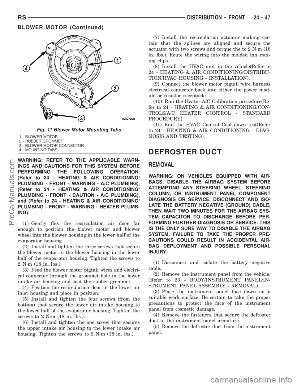
to access and remove the three screws that secure
the blower motor to the blower housing in the lower
half of the evaporator housing (Fig. 11).
(9) Gently flex the recirculation air door far
enough to remove the blower motor and blower wheel
from the blower housing in the lower half of the
evaporator housing.
INSTALLATION
The blower motor and blower wheel are serviced
only as a balanced unit. If either component is faulty
or damaged, the entire unit must be replaced.
Fig. 9 Lower Intake Air Housing
1 - LOWER INTAKE AIR HOUSING
2 - RECIRCULATION AIR DOOR ACTUATOR
3 - BLOWER MOTOR PIGTAIL WIRE CONNECTOR
4 - RUBBER GROMMET
5 - BLOWER MOTOR RESISTOR/POWER MODULE
6 - LOWER EVAPORATOR HOUSING
7 - UPPER INTAKE AIR HOUSING
8 - RECIRCULATION AIR DOOR
Fig. 10 Rubber Grommet - Typical
1 - BLOWER MOTOR PIGTAIL WIRE GROMMET
24 - 46 DISTRIBUTION - FRONTRS
BLOWER MOTOR (Continued)
ProCarManuals.com
Page 2044 of 2177
WARNING: REFER TO THE APPLICABLE WARN-
INGS AND CAUTIONS FOR THIS SYSTEM BEFORE
PERFORMING THE FOLLOWING OPERATION.
(Refer to 24 - HEATING & AIR CONDITIONING/
PLUMBING - FRONT - WARNING - A/C PLUMBING),
(Refer to 24 - HEATING & AIR CONDITIONING/
PLUMBING - FRONT - CAUTION - A/C PLUMBING),
and (Refer to 24 - HEATING & AIR CONDITIONING/
PLUMBING - FRONT - WARNING - HEATER PLUMB-
ING).
(1) Gently flex the recirculation air door far
enough to position the blower motor and blower
wheel into the blower housing in the lower half of the
evaporator housing.
(2) Install and tighten the three screws that secure
the blower motor to the blower housing in the lower
half of the evaporator housing. Tighten the screws to
2 N´m (18 in. lbs.).
(3) Feed the blower motor pigtail wires and electri-
cal connector through the grommet hole in the lower
intake air housing and seat the rubber grommet.
(4) Position the recirculation door in the lower air
inlet housing and place in position.
(5) Install and tighten the four screws (from the
bottom) that secure the lower air intake housing to
the lower half of the evaporator housing. Tighten the
screws to 2 N´m (18 in. lbs.).
(6) Install and tighten the one screw that secures
the upper intake air housing to the lower intake air
housing. Tighten the screws to 2 N´m (18 in. lbs.).(7) Install the recirculation actuator making cer-
tain that the splines are aligned and secure the
actuator with two screws and torque the to 2 N´m (18
in. lbs.). Route the wiring into the molded inn rout-
ing clips.
(8) Install the HVAC unit in the vehicle(Refer to
24 - HEATING & AIR CONDITIONING/DISTRIBU-
TION/HVAC HOUSING - INSTALLATION).
(9) Connect the blower motor pigtail wire harness
electrical connector back into either the power mod-
ule or resistor receptacle.
(10) Run the Heater-A/C Calibration procedure(Re-
fer to 24 - HEATING & AIR CONDITIONING/CON-
TROLS/A/C HEATER CONTROL - STANDARD
PROCEDURE).
(11) Run the HVAC Control Cool down test(Refer
to 24 - HEATING & AIR CONDITIONING - DIAG-
NOSIS AND TESTING).
DEFROSTER DUCT
REMOVAL
WARNING: ON VEHICLES EQUIPPED WITH AIR-
BAGS, DISABLE THE AIRBAG SYSTEM BEFORE
ATTEMPTING ANY STEERING WHEEL, STEERING
COLUMN, OR INSTRUMENT PANEL COMPONENT
DIAGNOSIS OR SERVICE. DISCONNECT AND ISO-
LATE THE BATTERY NEGATIVE (GROUND) CABLE,
THEN WAIT TWO MINUTES FOR THE AIRBAG SYS-
TEM CAPACITOR TO DISCHARGE BEFORE PER-
FORMING FURTHER DIAGNOSIS OR SERVICE. THIS
IS THE ONLY SURE WAY TO DISABLE THE AIRBAG
SYSTEM. FAILURE TO TAKE THE PROPER PRE-
CAUTIONS COULD RESULT IN ACCIDENTAL AIR-
BAG DEPLOYMENT AND POSSIBLE PERSONAL
INJURY.
(1) Disconnect and isolate the battery negative
cable.
(2) Remove the instrument panel from the vehicle.
(Refer to 23 - BODY/INSTRUMENT PANEL/IN-
STRUMENT PANEL ASSEMBLY - REMOVAL).
(3) Place the instrument panel face down on a
suitable work surface. Be certain to take the proper
precautions to protect the face of the instrument
panel from cosmetic damage.
(4) Remove the fasteners that secure the defroster
duct to the instrument panel armature.
(5) Remove the defroster duct from the instrument
panel.
Fig. 11 Blower Motor Mounting Tabs
1 - BLOWER MOTOR
2 - RUBBER GROMMET
3 - BLOWER MOTOR CONNECTOR
4 - MOUNTING TABS
RSDISTRIBUTION - FRONT24-47
BLOWER MOTOR (Continued)
ProCarManuals.com
Page 2045 of 2177
INSTALLATION
WARNING: ON VEHICLES EQUIPPED WITH AIR-
BAGS, DISABLE THE AIRBAG SYSTEM BEFORE
ATTEMPTING ANY STEERING WHEEL, STEERING
COLUMN, OR INSTRUMENT PANEL COMPONENT
DIAGNOSIS OR SERVICE. DISCONNECT AND ISO-
LATE THE BATTERY NEGATIVE (GROUND) CABLE,
THEN WAIT TWO MINUTES FOR THE AIRBAG SYS-
TEM CAPACITOR TO DISCHARGE BEFORE PER-
FORMING FURTHER DIAGNOSIS OR SERVICE. THIS
IS THE ONLY SURE WAY TO DISABLE THE AIRBAG
SYSTEM. FAILURE TO TAKE THE PROPER PRE-
CAUTIONS COULD RESULT IN ACCIDENTAL AIR-
BAG DEPLOYMENT AND POSSIBLE PERSONAL
INJURY.
(1) Position the defroster duct to the instrument
panel.
(2) Install the fasteners that secure the defroster
duct to the instrument panel armature.
(3) Reinstall the instrument panel in the vehicle.
(Refer to 23 - BODY/INSTRUMENT PANEL/IN-
STRUMENT PANEL ASSEMBLY - INSTALLA-
TION).
(4) Reconnect the battery negative cable.
DEMISTER DUCTS
REMOVAL
WARNING: ON VEHICLES EQUIPPED WITH AIR-
BAGS, DISABLE THE AIRBAG SYSTEM BEFORE
ATTEMPTING ANY STEERING WHEEL, STEERING
COLUMN, OR INSTRUMENT PANEL COMPONENT
DIAGNOSIS OR SERVICE. DISCONNECT AND ISO-
LATE THE BATTERY NEGATIVE (GROUND) CABLE,
THEN WAIT TWO MINUTES FOR THE AIRBAG SYS-
TEM CAPACITOR TO DISCHARGE BEFORE PER-
FORMING FURTHER DIAGNOSIS OR SERVICE. THIS
IS THE ONLY SURE WAY TO DISABLE THE AIRBAG
SYSTEM. FAILURE TO TAKE THE PROPER PRE-
CAUTIONS COULD RESULT IN ACCIDENTAL AIR-
BAG DEPLOYMENT AND POSSIBLE PERSONAL
INJURY.
(1) Disconnect and isolate the battery negative
cable.
(2) Remove the instrument panel from the vehicle.
(Refer to 23 - BODY/INSTRUMENT PANEL/IN-
STRUMENT PANEL ASSEMBLY - REMOVAL).
(3) Place the instrument panel face down on a
suitable work surface. Be certain to take the proper
precautions to protect the face of the instrument
panel from cosmetic damage.(4) Remove the fasteners that secure the demister
ducts to the instrument panel armature.
(5) Disengage the demister ducts from the demis-
ter outlets.
(6) Remove the demister ducts from the instru-
ment panel.
INSTALLATION
WARNING: ON VEHICLES EQUIPPED WITH AIR-
BAGS, DISABLE THE AIRBAG SYSTEM BEFORE
ATTEMPTING ANY STEERING WHEEL, STEERING
COLUMN, OR INSTRUMENT PANEL COMPONENT
DIAGNOSIS OR SERVICE. DISCONNECT AND ISO-
LATE THE BATTERY NEGATIVE (GROUND) CABLE,
THEN WAIT TWO MINUTES FOR THE AIRBAG SYS-
TEM CAPACITOR TO DISCHARGE BEFORE PER-
FORMING FURTHER DIAGNOSIS OR SERVICE. THIS
IS THE ONLY SURE WAY TO DISABLE THE AIRBAG
SYSTEM. FAILURE TO TAKE THE PROPER PRE-
CAUTIONS COULD RESULT IN ACCIDENTAL AIR-
BAG DEPLOYMENT AND POSSIBLE PERSONAL
INJURY.
(1) Position the demister ducts to the instrument
panel.
(2) Engage the demister ducts to the demister out-
lets.
(3) Install the fasteners that secure the demister
ducts to the instrument panel armature.
(4) Reinstall the instrument panel into the vehicle.
(Refer to 23 - BODY/INSTRUMENT PANEL/IN-
STRUMENT PANEL ASSEMBLY - INSTALLA-
TION).
(5) Reconnect the battery negative cable.
FLOOR DISTRIBUTION DUCTS
REMOVAL
(1) Roll back the carpet on the front floor from
under the instrument panel toward the rear of the
vehicle. (Refer to 23 - BODY/INTERIOR/CARPETS
AND FLOOR MATS - REMOVAL).
(2) Lift the center floor distribution duct upward
far enough to disengage its locator hole from the
weld stud on the front floor panel (Fig. 12).
(3) Pull the floor distribution duct assembly rear-
ward far enough to disengage the center floor distri-
bution duct from the outlet on the bottom of the
heater-A/C housing unit.
(4) Disassemble the right and/or left floor distribu-
tion ducts from the center floor distribution duct as
required.
24 - 48 DISTRIBUTION - FRONTRS
DEFROSTER DUCT (Continued)
ProCarManuals.com
Page 2046 of 2177

INSTALLATION
(1) Assemble the right and/or left floor distribution
ducts onto the center floor distribution duct as
required.
(2) Slide the floor distribution duct assembly
under the instrument panel center stack far enough
to engage the center floor distribution duct with the
outlet on the bottom of the heater-A/C housing unit.
(3) Align the locator hole on the center floor distri-
bution duct with the weld stud on the front floor
panel.
(4) Using hand pressure, push the locator hole of
the center floor distribution duct down over the weld
stud on the front floor panel.
(5) Reinstall the carpet onto the front floor panel
and under the instrument panel. (Refer to 23 -
BODY/INTERIOR/CARPETS AND FLOOR MATS -
INSTALLATION).
HVAC HOUSING
REMOVAL
WARNING: REFER TO THE APPLICABLE WARN-
INGS AND CAUTIONS FOR THIS SYSTEM BEFORE
PERFORMING THE FOLLOWING OPERATION.
(Refer to 24 - HEATING & AIR CONDITIONING/
PLUMBING - FRONT - WARNING - A/C PLUMBING),
(Refer to 24 - HEATING & AIR CONDITIONING/
PLUMBING - FRONT - CAUTION - A/C PLUMBING),
and (Refer to 24 - HEATING & AIR CONDITIONING/
PLUMBING - FRONT - WARNING - HEATER PLUMB-
ING).
WARNING: ON VEHICLES EQUIPPED WITH AIR-
BAGS, DISABLE THE AIRBAG SYSTEM BEFORE
ATTEMPTING ANY STEERING WHEEL, STEERING
COLUMN, OR INSTRUMENT PANEL COMPONENT
DIAGNOSIS OR SERVICE. DISCONNECT AND ISO-
LATE THE BATTERY NEGATIVE (GROUND) CABLE,
THEN WAIT TWO MINUTES FOR THE AIRBAG SYS-
TEM CAPACITOR TO DISCHARGE BEFORE PER-
FORMING FURTHER DIAGNOSIS OR SERVICE. THIS
IS THE ONLY SURE WAY TO DISABLE THE AIRBAG
SYSTEM. FAILURE TO TAKE THE PROPER PRE-
CAUTIONS COULD RESULT IN ACCIDENTAL AIR-
BAG DEPLOYMENT AND POSSIBLE PERSONAL
INJURY.
(1) Recover the refrigerant from the refrigerant
system. (Refer to 24 - HEATING & AIR CONDI-
TIONING/PLUMBING - FRONT/REFRIGERANT -
STANDARD PROCEDURE - REFRIGERANT
RECOVERY).
(2) Drain the engine cooling system. (Refer to 7 -
COOLING - STANDARD PROCEDURE - COOLING
SYSTEM DRAIN).
(3) Disconnect and isolate the battery negative
cable.
(4) Remove the windshield wiper module from the
vehicle(Refer to 8 - ELECTRICAL/WIPERS/WASH-
ERS/WIPER MODULE - REMOVAL).
Fig. 12 Floor Distribution Ducts
1 - CENTER FLOOR DISTRIBUTION DUCT
2 - RIGHT FLOOR DISTRIBUTION DUCT
3 - LEFT FLOOR DISTRIBUTION DUCT
4 - WELD STUD
RSDISTRIBUTION - FRONT24-49
FLOOR DISTRIBUTION DUCTS (Continued)
ProCarManuals.com
Page 2048 of 2177
(8) Install the windshield wiper module(Refer to 8
- ELECTRICAL/WIPERS/WASHERS/WIPER MOD-
ULE - INSTALLATION).
(9) Reconnect the battery negative cable.
(10) Refill the engine cooling system. (Refer to 7 -
COOLING - STANDARD PROCEDURE - COOLING
SYSTEM REFILL).
(11) Evacuate the refrigerant system. (Refer to 24 -
HEATING & AIR CONDITIONING/PLUMBING -
FRONT/REFRIGERANT - STANDARD PROCE-
DURE - REFRIGERANT SYSTEM EVACUATE).
(12) Charge the refrigerant system. (Refer to 24 -
HEATING & AIR CONDITIONING/PLUMBING -
FRONT/REFRIGERANT - STANDARD PROCE-
DURE - REFRIGERANT SYSTEM CHARGE).
PANEL DUCTS
REMOVAL
WARNING: ON VEHICLES EQUIPPED WITH AIR-
BAGS, DISABLE THE AIRBAG SYSTEM BEFORE
ATTEMPTING ANY STEERING WHEEL, STEERING
COLUMN, OR INSTRUMENT PANEL COMPONENT
DIAGNOSIS OR SERVICE. DISCONNECT AND ISO-
LATE THE BATTERY NEGATIVE (GROUND) CABLE,
THEN WAIT TWO MINUTES FOR THE AIRBAG SYS-
TEM CAPACITOR TO DISCHARGE BEFORE PER-
FORMING FURTHER DIAGNOSIS OR SERVICE. THIS
IS THE ONLY SURE WAY TO DISABLE THE AIRBAG
SYSTEM. FAILURE TO TAKE THE PROPER PRE-CAUTIONS COULD RESULT IN ACCIDENTAL AIR-
BAG DEPLOYMENT AND POSSIBLE PERSONAL
INJURY.
(1) Disconnect and isolate the battery negative
cable.
(2) Remove the instrument panel from the vehicle.
(Refer to 23 - BODY/INSTRUMENT PANEL/IN-
STRUMENT PANEL ASSEMBLY - REMOVAL).
(3) Place the instrument panel face down on a
suitable work surface. Be certain to take the proper
precautions to protect the face of the instrument
panel from cosmetic damage.
(4) Remove the fasteners that secure the panel
ducts to the instrument panel armature.
(5) Disengage the panel ducts from the panel out-
lets.
(6) Remove the panel ducts from the instrument
panel.
INSTALLATION
(1) Position the panel ducts to the instrument
panel.
(2) Engage the panel ducts to the panel outlets.
(3) Install the fasteners that secure the panel
ducts to the instrument panel armature.
(4) Reinstall the instrument panel into the vehicle.
(Refer to 23 - BODY/INSTRUMENT PANEL/IN-
STRUMENT PANEL ASSEMBLY - INSTALLA-
TION).
(5) Reconnect the battery negative cable.
RSDISTRIBUTION - FRONT24-51
HVAC HOUSING (Continued)
ProCarManuals.com
Page 2053 of 2177
REMOVAL
The rear blower motor and blower wheel are ser-
viced only as a balanced unit. If either component is
faulty or damaged, the entire unit must be replaced.
WARNING: REFER TO THE APPLICABLE WARN-
INGS AND CAUTIONS FOR THIS SYSTEM BEFORE
PERFORMING THE FOLLOWING OPERATION.
(Refer to 24 - HEATING & AIR CONDITIONING/
PLUMBING - FRONT - WARNING - A/C PLUMBING),
(Refer to 24 - HEATING & AIR CONDITIONING/
PLUMBING - FRONT - CAUTION - A/C PLUMBING),
and (Refer to 24 - HEATING & AIR CONDITIONING/
PLUMBING - FRONT - WARNING - HEATER PLUMB-
ING).
(1) Remove the rear heater-A/C unit housing from
the vehicle. (Refer to 24 - HEATING & AIR CONDI-
TIONING/DISTRIBUTION - REAR/REAR HEATER-
A/C HOUSING - REMOVAL).
(2) Disconnect the rear blower motor pigtail wire
connector. With manual temperature control, the
blower pigtail wire is connected to a take out and
connector of the rear HVAC wire harness. With auto-
matic temperature control, the blower pigtail wire is
connected to a receptacle on the blower power mod-
ule.
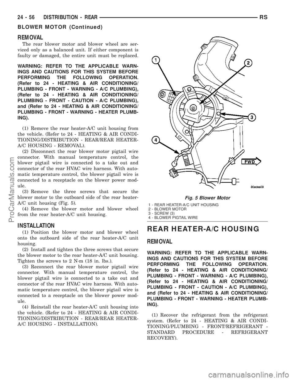
(3) Remove the three screws that secure the
blower motor to the outboard side of the rear heater-
A/C unit housing (Fig. 5).
(4) Remove the blower motor and blower wheel
from the rear heater-A/C unit housing.
INSTALLATION
(1) Position the blower motor and blower wheel
onto the outboard side of the rear heater-A/C unit
housing.
(2) Install and tighten the three screws that secure
the blower motor to the rear heater-A/C unit housing.
Tighten the screws to 2 N´m (18 in. lbs.).
(3) Reconnect the rear blower motor pigtail wire
connector. With manual temperature control, the
blower pigtail wire is connected to a take out and
connector of the rear HVAC wire harness. With auto-
matic temperature control, the blower pigtail wire is
connected to a receptacle on the blower power mod-
ule.
(4) Reinstall the rear heater-A/C unit housing into
the vehicle. (Refer to 24 - HEATING & AIR CONDI-
TIONING/DISTRIBUTION - REAR/REAR HEATER-
A/C HOUSING - INSTALLATION).REAR HEATER-A/C HOUSING
REMOVAL
WARNING: REFER TO THE APPLICABLE WARN-
INGS AND CAUTIONS FOR THIS SYSTEM BEFORE
PERFORMING THE FOLLOWING OPERATION.
(Refer to 24 - HEATING & AIR CONDITIONING/
PLUMBING - FRONT - WARNING - A/C PLUMBING),
(Refer to 24 - HEATING & AIR CONDITIONING/
PLUMBING - FRONT - CAUTION - A/C PLUMBING),
and (Refer to 24 - HEATING & AIR CONDITIONING/
PLUMBING - FRONT - WARNING - HEATER PLUMB-
ING).
(1) Recover the refrigerant from the refrigerant
system. (Refer to 24 - HEATING & AIR CONDI-
TIONING/PLUMBING - FRONT/REFRIGERANT -
STANDARD PROCEDURE - REFRIGERANT
RECOVERY).
Fig. 5 Blower Motor
1 - REAR HEATER-A/C UNIT HOUSING
2 - BLOWER MOTOR
3 - SCREW (3)
4 - BLOWER PIGTAIL WIRE
24 - 56 DISTRIBUTION - REARRS
BLOWER MOTOR (Continued)
ProCarManuals.com
Page 2057 of 2177
PLUMBING - FRONT
TABLE OF CONTENTS
page page
PLUMBING - FRONT
WARNING
WARNING...........................61
WARNING - A/C PLUMBING.............61
CAUTION - A/C PLUMBING...............61
A/C COMPRESSOR
DESCRIPTION.........................63
OPERATION...........................63
DIAGNOSIS AND TESTING - COMPRESSOR
NOISE DIAGNOSIS....................63
REMOVAL
REMOVAL - COMPRESSOR - 2.4/3.3/3.8L
ENGINES............................64
REMOVAL - COMPRESSOR MOUNTING
BRACKET - 2.4L ENGINE...............65
INSTALLATION
INSTALLATION - COMPRESSOR..........65
INSTALLATION - COMPRESSOR
MOUNTING BRACKET - 2.4L ENGINE......66
CONDENSER
DESCRIPTION.........................66
OPERATION...........................66
REMOVAL.............................66
INSTALLATION.........................67
DISCHARGE LINE
REMOVAL.............................68
INSTALLATION.........................69
EVAPORATOR
DESCRIPTION.........................69
OPERATION...........................70
REMOVAL.............................70
INSTALLATION.........................71
EXPANSION VALVE
DESCRIPTION.........................72
OPERATION...........................72
DIAGNOSIS AND TESTING - EXPANSION
VALVE ..............................72
REMOVAL.............................73
INSTALLATION.........................74
HEATER CORE
DESCRIPTION.........................74
OPERATION...........................74
REMOVAL
REMOVAL- HEATER CORE EXTENSION
TUBES.............................75REMOVAL - HEATER CORE.............76
INSTALLATION
INSTALLATION- HEATER CORE
EXTENSION TUBES...................77
INSTALLATION - HEATER CORE..........78
HEATER HOSE
REMOVAL.............................78
INSTALLATION.........................80
LIQUID LINE
REMOVAL.............................80
INSTALLATION.........................82
RECEIVER/DRIER
DESCRIPTION.........................83
OPERATION...........................84
REMOVAL.............................84
INSTALLATION.........................84
REFRIGERANT
DESCRIPTION.........................85
OPERATION...........................85
DIAGNOSIS AND TESTING
DIAGNOSIS AND TESTING - REFRIGERANT
SYSTEM CHARGE LEVEL...............85
DIAGNOSIS AND TESTING - REFRIGERANT
SYSTEM LEAKS......................86
STANDARD PROCEDURE
STANDARD PROCEDURE - REFRIGERANT
SYSTEM SERVICE EQUIPMENT..........87
STANDARD PROCEDURE - REFRIGERANT
SYSTEM CHARGE.....................88
STANDARD PROCEDURE - REFRIGERANT
SYSTEM EVACUATE...................89
STANDARD PROCEDURE - REFRIGERANT
RECOVERY..........................89
REFRIGERANT OIL
DESCRIPTION.........................90
OPERATION...........................90
STANDARD PROCEDURE - REFRIGERANT
OIL LEVEL...........................90
SUCTION LINE
REMOVAL.............................90
INSTALLATION.........................91
SERVICE PORTS
REMOVAL.............................92
INSTALLATION.........................93
24 - 60 PLUMBING - FRONTRS
ProCarManuals.com
Page 2058 of 2177
PLUMBING - FRONT
WARNING
WARNING
WARNING:: THE ENGINE COOLING SYSTEM IS
DESIGNED TO DEVELOP INTERNAL PRESSURES
OF 97 TO 123 KILOPASCALS (14 TO 18 POUNDS
PER SQUARE INCH). DO NOT REMOVE OR
LOOSEN THE COOLANT PRESSURE CAP, CYLIN-
DER BLOCK DRAIN PLUGS, RADIATOR DRAIN,
RADIATOR HOSES, HEATER HOSES, OR HOSE
CLAMPS WHILE THE SYSTEM IS HOT AND UNDER
PRESSURE. FAILURE TO OBSERVE THIS WARNING
CAN RESULT IN SERIOUS BURNS FROM THE
HEATED ENGINE COOLANT. ALLOW THE VEHICLE
TO COOL FOR A MINIMUM OF 15 MINUTES
BEFORE OPENING THE COOLING SYSTEM FOR
SERVICE.
WARNING: THE ENGINE COOLING SYSTEM CON-
TAINS ANTIFREEZE. ANTIFREEZE IS AN ETHYLENE
GLYCOL BASED COOLANT AND IS HARMFUL IF
SWALLOWED OR IF THE VAPORS ARE INHALED. IF
SWALLOWED, DRINK TWO GLASSES OF WATER
AND INDUCE VOMITING. IF VAPORS ARE INHALED,
MOVE TO AN AREA FOR FRESH AIR. SEEK MEDI-
CAL ATTENTION IMMEDIATELY. DO NOT STORE IN
OPEN OR UNMARKED CONTAINERS. WASH SKIN
AND CLOTHING THOROUGHLY AFTER COMING IN
CONTACT WITH ETHYLENE GLYCOL. KEEP OUT
OF REACH OF CHILDREN.
WARNING: DISPOSE OF ETHYLENE GLYCOL
BASED COOLANT PROPERLY. CONTACT YOUR
DEALER OR A LOCAL GOVERNMENT AGENCY FOR
THE LOCATION OF AN APPROVED ETHYLENE GLY-
COL COLLECTION AND/OR RECYCLING CENTER IN
YOUR AREA.
WARNING - A/C PLUMBING
WARNING:: THE AIR CONDITIONING SYSTEM CON-
TAINS REFRIGERANT UNDER HIGH PRESSURE.
SEVERE PERSONAL INJURY MAY RESULT FROM
IMPROPER SERVICE PROCEDURES. REPAIRS
SHOULD ONLY BE PERFORMED BY QUALIFIED
SERVICE PERSONNEL.
WARNING: AVOID BREATHING THE REFRIGERANT
AND REFRIGERANT OIL VAPOR OR MIST. EXPO-
SURE MAY IRRITATE THE EYES, NOSE, AND/ORTHROAT. WEAR EYE PROTECTION WHEN SERVIC-
ING THE AIR CONDITIONING REFRIGERANT SYS-
TEM. SERIOUS EYE INJURY CAN RESULT FROM
DIRECT CONTACT WITH THE REFRIGERANT. IF
EYE CONTACT OCCURS, SEEK MEDICAL ATTEN-
TION IMMEDIATELY.
WARNING: DO NOT EXPOSE THE REFRIGERANT
TO OPEN FLAME. POISONOUS GAS IS CREATED
WHEN REFRIGERANT IS BURNED. AN ELEC-
TRONIC LEAK DETECTOR IS RECOMMENDED.
WARNING: IF ACCIDENTAL SYSTEM DISCHARGE
OCCURS, VENTILATE THE WORK AREA BEFORE
RESUMING SERVICE. LARGE AMOUNTS OF
REFRIGERANT RELEASED IN A CLOSED WORK
AREA WILL DISPLACE THE OXYGEN AND CAUSE
SUFFOCATION.
WARNING: THE EVAPORATION RATE OF R-134a
REFRIGERANT AT AVERAGE TEMPERATURE AND
ALTITUDE IS EXTREMELY HIGH. AS A RESULT,
ANYTHING THAT COMES IN CONTACT WITH THE
REFRIGERANT WILL FREEZE. ALWAYS PROTECT
THE SKIN OR DELICATE OBJECTS FROM DIRECT
CONTACT WITH THE REFRIGERANT.
WARNING: THE R-134a SERVICE EQUIPMENT OR
THE VEHICLE REFRIGERANT SYSTEM SHOULD
NOT BE PRESSURE TESTED OR LEAK TESTED
WITH COMPRESSED AIR. SOME MIXTURES OF AIR
AND R-134a HAVE BEEN SHOWN TO BE COMBUS-
TIBLE AT ELEVATED PRESSURES. THESE MIX-
TURES ARE POTENTIALLY DANGEROUS, AND MAY
RESULT IN FIRE OR EXPLOSION CAUSING INJURY
OR PROPERTY DAMAGE.
CAUTION - A/C PLUMBING
CAUTION:: Liquid refrigerant is corrosive to metal
surfaces. Follow the operating instructions supplied
with the service equipment being used.
CAUTION: Never add R-12 to a refrigerant system
designed to use R-134a. Damage to the system will
result.
CAUTION: R-12 refrigerant oil must not be mixed
with R-134a refrigerant oil. They are not compatible.
RSPLUMBING - FRONT24-61
ProCarManuals.com