2003 CHRYSLER CARAVAN tire size
[x] Cancel search: tire sizePage 1303 of 2177
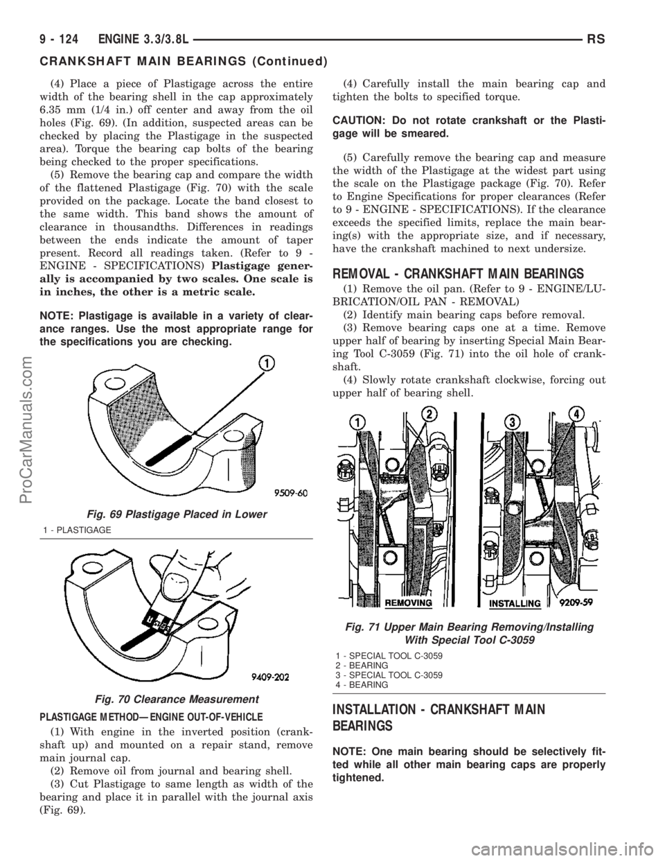
(4) Place a piece of Plastigage across the entire
width of the bearing shell in the cap approximately
6.35 mm (1/4 in.) off center and away from the oil
holes (Fig. 69). (In addition, suspected areas can be
checked by placing the Plastigage in the suspected
area). Torque the bearing cap bolts of the bearing
being checked to the proper specifications.
(5) Remove the bearing cap and compare the width
of the flattened Plastigage (Fig. 70) with the scale
provided on the package. Locate the band closest to
the same width. This band shows the amount of
clearance in thousandths. Differences in readings
between the ends indicate the amount of taper
present. Record all readings taken. (Refer to 9 -
ENGINE - SPECIFICATIONS)Plastigage gener-
ally is accompanied by two scales. One scale is
in inches, the other is a metric scale.
NOTE: Plastigage is available in a variety of clear-
ance ranges. Use the most appropriate range for
the specifications you are checking.
PLASTIGAGE METHODÐENGINE OUT-OF-VEHICLE
(1) With engine in the inverted position (crank-
shaft up) and mounted on a repair stand, remove
main journal cap.
(2) Remove oil from journal and bearing shell.
(3) Cut Plastigage to same length as width of the
bearing and place it in parallel with the journal axis
(Fig. 69).(4) Carefully install the main bearing cap and
tighten the bolts to specified torque.
CAUTION: Do not rotate crankshaft or the Plasti-
gage will be smeared.
(5) Carefully remove the bearing cap and measure
the width of the Plastigage at the widest part using
the scale on the Plastigage package (Fig. 70). Refer
to Engine Specifications for proper clearances (Refer
to 9 - ENGINE - SPECIFICATIONS). If the clearance
exceeds the specified limits, replace the main bear-
ing(s) with the appropriate size, and if necessary,
have the crankshaft machined to next undersize.
REMOVAL - CRANKSHAFT MAIN BEARINGS
(1) Remove the oil pan. (Refer to 9 - ENGINE/LU-
BRICATION/OIL PAN - REMOVAL)
(2) Identify main bearing caps before removal.
(3) Remove bearing caps one at a time. Remove
upper half of bearing by inserting Special Main Bear-
ing Tool C-3059 (Fig. 71) into the oil hole of crank-
shaft.
(4) Slowly rotate crankshaft clockwise, forcing out
upper half of bearing shell.
INSTALLATION - CRANKSHAFT MAIN
BEARINGS
NOTE: One main bearing should be selectively fit-
ted while all other main bearing caps are properly
tightened.
Fig. 69 Plastigage Placed in Lower
1 - PLASTIGAGE
Fig. 70 Clearance Measurement
Fig. 71 Upper Main Bearing Removing/Installing
With Special Tool C-3059
1 - SPECIAL TOOL C-3059
2 - BEARING
3 - SPECIAL TOOL C-3059
4 - BEARING
9 - 124 ENGINE 3.3/3.8LRS
CRANKSHAFT MAIN BEARINGS (Continued)
ProCarManuals.com
Page 1400 of 2177
CONDITION POSSIBLE CAUSES CORRECTION
SQUEAK OR RUBBING
SOUND1. Steering column shroud rubbing. 1. Realign shrouds as necessary.
2. Steering column shaft rubbing. 2. Move or realign item rubbing shaft.
3. Clockspring noisy. 3. Remove clockspring. Reinstall wheel.
If noise is gone, replace clockspring.
4. Seal lubrication inadequate. 4. Lube seal (if external).
5. Steering gear internally noisy. 5. Replace steering gear (if no other
cause can be found).
SCRUBBING OR
KNOCKING NOISE.1. Incorrect tire or wheel size. 1. Replace incorrect size tire or wheel
with size used as original equipment.
2. Interference between steering
gear and other vehicle components.2. Check for bent or misaligned
components and correct as necessary.
3. Steering gear internal stops worn
excessively allowing tires to be
steered excessively far.3. Replace steering gear.
NOTE: * There is some noise in all power steering
systems. One of the most common is a hissing
sound evident when turning the steering wheel
when at a standstill or when parking and the steer-
ing wheel is at the end of its travel. Hiss is a very
high frequency noise similar to that experienced
while slowly closing a water tap. The noise is
present in every valve and results when high veloc-
ity fluid passes valve orifice edges. There is no
relationship between this noise and the perfor-
mance of the steering system.NOTE: ** A light clunk may be felt or heard during
steering wheel reversal while vehicle is stationary.
This results from internal steering gear rack move-
ment at the bushings and in no way affects the per-
formance of the steering system. This movement
may be felt in the steering components during
steering wheel reversal.
NOTE: *** Power steering pump growl/moan/groan
results from the development of high pressure fluid
flow. Normally this noise level should not be high
enough to be objectionable.
STEERING WHEEL FEEL
CONDITION POSSIBLE CAUSES CORRECTION
STEERING WHEEL/
COLUMN CLICKING,
CLUNKING OR RATTLING.1. Loose steering coupling pinch
bolt.1. Replace pinch bolt and torque to
specifications.
2. Steering column bearings. 2. Replace steering column.
3. Excessive intermediate shaft
coupling free-play.3. Replace intermediate shaft.
STEERING WHEEL HAS
FORE AND AFT
LOOSENESS.1. Steering wheel retaining nut not
properly tightened and torqued.1. Tighten the steering wheel retaining nut
to its specified torque.
2. Steering column lower bearing
spring retainer slipped on steering
column shaft.2. Replace steering column.
3. Loose steering column to
instrument panel fasteners.3. Tighten fasteners to specified torque.
RSSTEERING19-5
STEERING (Continued)
ProCarManuals.com
Page 1423 of 2177
(5) Raise vehicle. (Refer to LUBRICATION &
MAINTENANCE/HOISTING - STANDARD PROCE-
DURE)
(6) Remove front wheel and tire assemblies.
(7) Remove front emissions vapor canister. (Refer
to 25 - EMISSIONS CONTROL/EVAPORATIVE
EMISSIONS/VAPOR CANISTER - REMOVAL)
(8) Remove a single hose at power steering cooler
and allow fluid to drain.
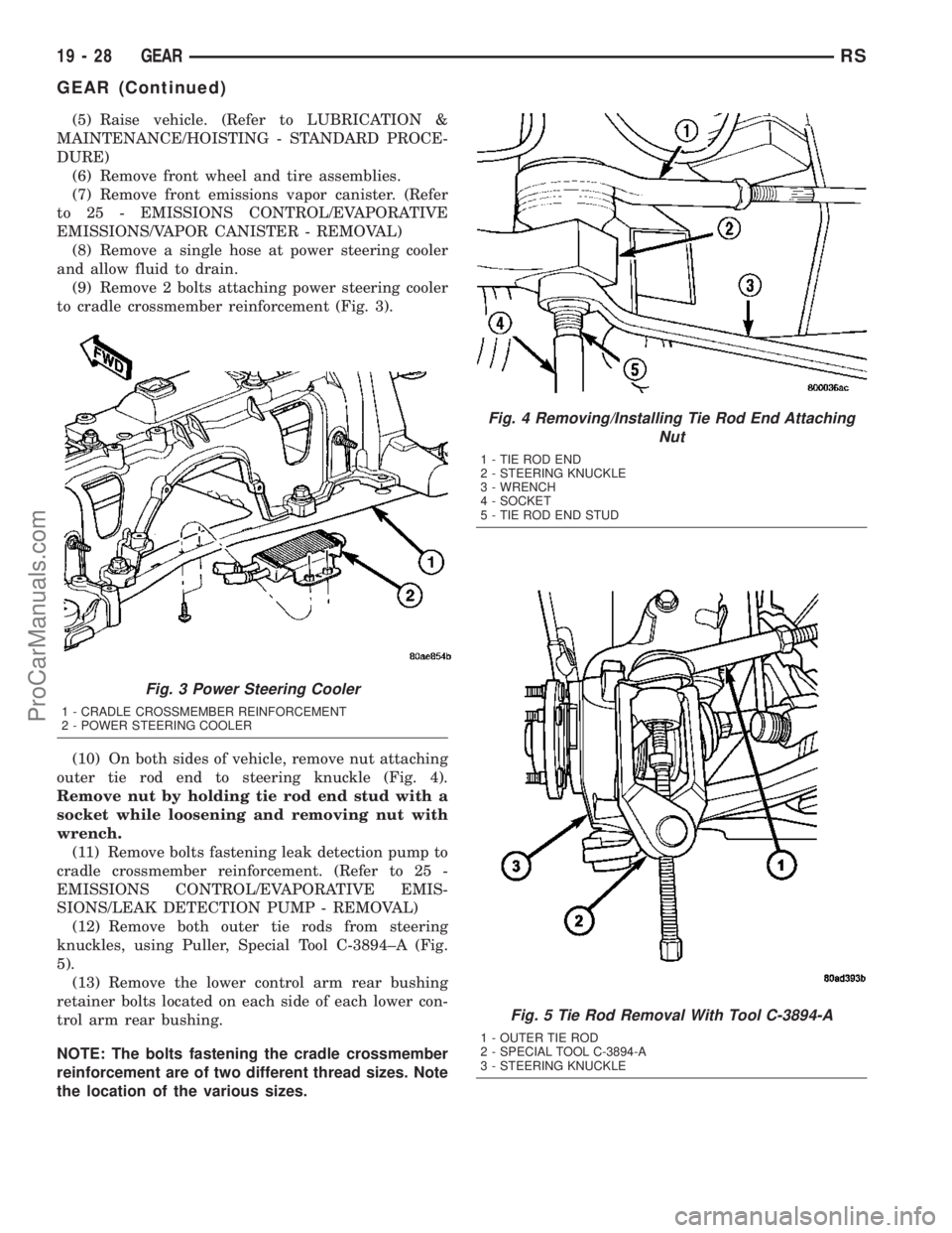
(9) Remove 2 bolts attaching power steering cooler
to cradle crossmember reinforcement (Fig. 3).
(10) On both sides of vehicle, remove nut attaching
outer tie rod end to steering knuckle (Fig. 4).
Remove nut by holding tie rod end stud with a
socket while loosening and removing nut with
wrench.
(11) Remove bolts fastening leak detection pump to
cradle crossmember reinforcement. (Refer to 25 -
EMISSIONS CONTROL/EVAPORATIVE EMIS-
SIONS/LEAK DETECTION PUMP - REMOVAL)
(12) Remove both outer tie rods from steering
knuckles, using Puller, Special Tool C-3894±A (Fig.
5).
(13) Remove the lower control arm rear bushing
retainer bolts located on each side of each lower con-
trol arm rear bushing.
NOTE: The bolts fastening the cradle crossmember
reinforcement are of two different thread sizes. Note
the location of the various sizes.
Fig. 3 Power Steering Cooler
1 - CRADLE CROSSMEMBER REINFORCEMENT
2 - POWER STEERING COOLER
Fig. 4 Removing/Installing Tie Rod End Attaching
Nut
1 - TIE ROD END
2 - STEERING KNUCKLE
3 - WRENCH
4 - SOCKET
5 - TIE ROD END STUD
Fig. 5 Tie Rod Removal With Tool C-3894-A
1 - OUTER TIE ROD
2 - SPECIAL TOOL C-3894-A
3 - STEERING KNUCKLE
19 - 28 GEARRS
GEAR (Continued)
ProCarManuals.com
Page 1426 of 2177
REMOVAL - RHD GEAR
(1) Remove cap from power steering fluid reser-
voir.
(2) Using a siphon pump, remove as much fluid as
possible from the power steering fluid reservoir.
CAUTION: Locking the steering column in the
straight-ahead position will prevent the clockspring
from being accidentally over-extended when the
steering column is disconnected from the interme-
diate steering coupler.
(3) Position the steering wheel in the STRAIGHT-
AHEAD position. Lock the steering wheel in place
using a steering wheel holding tool.
(4) With the ignition key in the locked position
turn the steering wheel to the left until the steering
wheel is in the locked position.
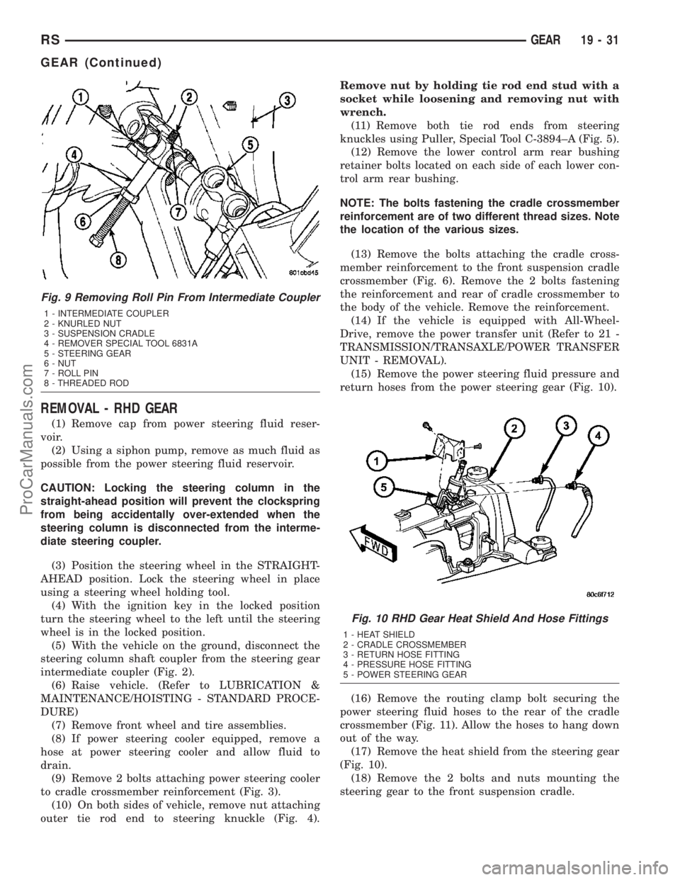
(5) With the vehicle on the ground, disconnect the
steering column shaft coupler from the steering gear
intermediate coupler (Fig. 2).
(6) Raise vehicle. (Refer to LUBRICATION &
MAINTENANCE/HOISTING - STANDARD PROCE-
DURE)
(7) Remove front wheel and tire assemblies.
(8) If power steering cooler equipped, remove a
hose at power steering cooler and allow fluid to
drain.
(9) Remove 2 bolts attaching power steering cooler
to cradle crossmember reinforcement (Fig. 3).
(10) On both sides of vehicle, remove nut attaching
outer tie rod end to steering knuckle (Fig. 4).Remove nut by holding tie rod end stud with a
socket while loosening and removing nut with
wrench.
(11) Remove both tie rod ends from steering
knuckles using Puller, Special Tool C-3894±A (Fig. 5).
(12) Remove the lower control arm rear bushing
retainer bolts located on each side of each lower con-
trol arm rear bushing.
NOTE: The bolts fastening the cradle crossmember
reinforcement are of two different thread sizes. Note
the location of the various sizes.
(13) Remove the bolts attaching the cradle cross-
member reinforcement to the front suspension cradle
crossmember (Fig. 6). Remove the 2 bolts fastening
the reinforcement and rear of cradle crossmember to
the body of the vehicle. Remove the reinforcement.
(14) If the vehicle is equipped with All-Wheel-
Drive, remove the power transfer unit (Refer to 21 -
TRANSMISSION/TRANSAXLE/POWER TRANSFER
UNIT - REMOVAL).
(15) Remove the power steering fluid pressure and
return hoses from the power steering gear (Fig. 10).
(16) Remove the routing clamp bolt securing the
power steering fluid hoses to the rear of the cradle
crossmember (Fig. 11). Allow the hoses to hang down
out of the way.
(17) Remove the heat shield from the steering gear
(Fig. 10).
(18) Remove the 2 bolts and nuts mounting the
steering gear to the front suspension cradle.
Fig. 9 Removing Roll Pin From Intermediate Coupler
1 - INTERMEDIATE COUPLER
2 - KNURLED NUT
3 - SUSPENSION CRADLE
4 - REMOVER SPECIAL TOOL 6831A
5 - STEERING GEAR
6 - NUT
7 - ROLL PIN
8 - THREADED ROD
Fig. 10 RHD Gear Heat Shield And Hose Fittings
1 - HEAT SHIELD
2 - CRADLE CROSSMEMBER
3 - RETURN HOSE FITTING
4 - PRESSURE HOSE FITTING
5 - POWER STEERING GEAR
RSGEAR19-31
GEAR (Continued)
ProCarManuals.com
Page 1428 of 2177
CAUTION: Proper torque on the cradle reinforce-
ment to suspension cradle mounting bolts is very
important.
(7) Install the reinforcement on the front suspen-
sion cradle crossmember and install the bolts attach-
ing the reinforcement to the cradle crossmember
(Fig. 6). Tighten the M-14 size bolts to a torque of
153 N´m (113 ft. lbs.). Tighten the M-12 size bolts to
a torque of 106 N´m (78 ft. lbs.).
(8) Install the lower control arm rear bushing
retainer bolts (M-10 size) through reinforcement on
each side of each lower control arm rear bushing.
Tighten bolts to a torque of 61 N´m (45 ft. lbs.).
(9) Install the two bolts and bushings attaching
the reinforcement and rear of cradle crossmember to
body of vehicle (Fig. 6). Tighten bolts to a torque of
163 N´m (120 ft. lbs.).
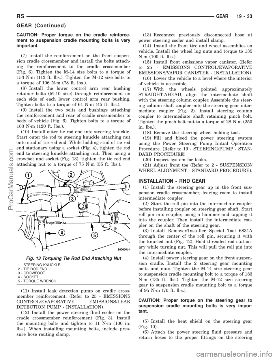
(10) Install outer tie rod end into steering knuckle.
Start outer tie rod to steering knuckle attaching nut
onto stud of tie rod end. While holding stud of tie rod
end stationary using a socket (Fig. 4), tighten tie rod
end to steering knuckle attaching nut. Then using a
crowfoot and socket (Fig. 13), tighten the tie rod end
attaching nut to a torque of 75 N´m (55 ft. lbs.).
(11) Install leak detection pump on cradle cross-
member reinforcement. (Refer to 25 - EMISSIONS
CONTROL/EVAPORATIVE EMISSIONS/LEAK
DETECTION PUMP - INSTALLATION)
(12) Install the power steering fluid cooler on the
cradle crossmember reinforcement (Fig. 3). Install
the mounting bolts and tighten to 11 N´m (100 in.
lbs.). When installing mounting bolts, include pres-
sure hose routing clamp.(13) Reconnect previously disconnected hose at
power steering cooler and install clamp.
(14) Install the front tire and wheel assemblies on
vehicle. Install the wheel lug nuts and torque to 135
N´m (100 ft. lbs.).
(15) Install front emissions vapor canister. (Refer
to 25 - EMISSIONS CONTROL/EVAPORATIVE
EMISSIONS/VAPOR CANISTER - INSTALLATION)
(16) Lower the vehicle to a level where the interior
of vehicle is accessible.
(17) With the wheels pointed approximately
STRAIGHT-AHEAD, align the intermediate shaft
with the steering column coupler. Assemble the steer-
ing column shaft coupler onto the steering gear inter-
mediate coupler (Fig. 2). Install steering column
coupler to intermediate shaft retaining pinch bolt.
Tighten the pinch bolt nut to a torque of 28 N´m (250
in. lbs.).
(18) Remove the steering wheel holding tool.
(19) Fill and bleed the power steering system
using the Power Steering Pump Initial Operation
Procedure. (Refer to 19 - STEERING/PUMP - STAN-
DARD PROCEDURE)
(20) Inspect system for leaks.
(21) Adjust front toe (Refer to 2 - SUSPENSION/
WHEEL ALIGNMENT - STANDARD PROCEDURE).
INSTALLATION - RHD GEAR
(1) Install the steering gear up in the front sus-
pension cradle crossmember, leaving room to install
intermediate coupler.
(2) Start the roll pin into the intermediate coupler
before installing coupler on steering gear shaft. Start
roll pin into coupler, using a hammer and tapping it
into the coupler. Then install the intermediate cou-
pler on the shaft of the steering gear.
(3) Install Remover/Installer Special Tool 6831A
through the center of the roll pin, securing it with
the knurled nut (Fig. 12). Hold threaded rod station-
ary while turning nut. This will pull the roll pin into
the intermediate coupler.
(4) Install power steering gear on the front suspen-
sion cradle. Install the 2 steering gear mounting
bolts and nuts. Tighten the M-14 size steering gear
to suspension cradle mounting bolt to a torque of 183
N´m (135 ft. lbs.). Tighten the M-12 size steering
gear to suspension cradle mounting bolt to a torque
of 95 N´m (70 ft. lbs.).
CAUTION: Proper torque on the steering gear to
suspension cradle mounting bolts is very impor-
tant.
(5) Install the heat shield on the steering gear
(Fig. 10).
(6) Attach the power steering fluid pressure and
return hoses to the proper fittings on the steering
Fig. 13 Torquing Tie Rod End Attaching Nut
1 - STEERING KNUCKLE
2 - TIE ROD END
3 - CROWFOOT
4 - SOCKET
5 - TORQUE WRENCH
RSGEAR19-33
GEAR (Continued)
ProCarManuals.com
Page 1429 of 2177
gear (Fig. 10). Do not fully tighten the fittings at this
time.
(7) Install the routing clamp with the bolt securing
the power steering fluid hoses to the rear of the cra-
dle crossmember (Fig. 11).
(8) Using a crowfoot wrench on a torque wrench,
tighten the power steering fluid hose tube nuts at the
gear to a torque of 31 N´m (275 in. lbs.).
(9) Install tie rod end into steering knuckle. Start
tie rod end to steering knuckle attaching nut onto
stud of tie rod end. While holding stud of tie rod end
stationary using a socket (Fig. 4), tighten tie rod end
to steering knuckle attaching nut. Then using a
crowfoot and socket (Fig. 13), tighten the tie rod end
attaching nut to a torque of 75 N´m (55 ft. lbs.).
(10) If the vehicle is equipped with All-Wheel-
Drive, install the power transfer unit (Refer to 21 -
TRANSMISSION/TRANSAXLE/POWER TRANSFER
UNIT - INSTALLATION).
CAUTION: Proper torque on the cradle reinforce-
ment to suspension cradle mounting bolts is very
important.
(11) Install the reinforcement on the front suspen-
sion cradle crossmember and install the bolts attach-
ing the reinforcement to the cradle crossmember
(Fig. 6). Tighten the M-14 size bolts to a torque of
163 N´m (120 ft. lbs.). Tighten the M-12 size bolts to
a torque of 108 N´m (80 ft. lbs.).
(12) Install the lower control arm rear bushing
retainer bolts through reinforcement on each side of
each lower control arm rear bushing. Tighten bolts to
a torque of 61 N´m (45 ft. lbs.).
(13) Install the two bolts and bushings attaching
the reinforcement and rear of cradle crossmember to
body of vehicle (Fig. 6). Tighten bolts to a torque of
163 N´m (120 ft. lbs.).
(14) If power steering cooler equipped, install the
previously disconnected power steering cooler hose on
the cooler. Install the clamp.
(15) If power steering cooler equipped, install the
power steering fluid cooler on the cradle crossmem-
ber reinforcement (Fig. 3). Install the mounting bolts
and tighten to 11 N´m (100 in. lbs.).
(16) Install the front tire and wheel assemblies on
vehicle. Install the wheel mounting lug nuts and
tighten to a torque to 135 N´m (100 ft. lbs.).
(17) Lower the vehicle to a level were the interior
of vehicle is accessible (keeping tires off the ground).
(18) With the wheels pointed approximately
STRAIGHT-AHEAD, align the intermediate shaft
with the steering column coupler. Assemble the steer-
ing column shaft coupler onto the steering gear inter-
mediate coupler (Fig. 2). Install steering column
coupler to intermediate shaft retaining pinch bolt.Tighten the pinch bolt nut to a torque of 28 N´m (250
in. lbs.).
(19) Remove the steering wheel holding tool.
(20) Perform the POWER STEERING PUMP INI-
TIAL OPERATION procedure to properly fill and
bleed the power steering system. (Refer to 19 -
STEERING/PUMP - STANDARD PROCEDURE)
(21) Inspect for leaks.
(22) Adjust front wheel toe (Refer to 2 - SUSPEN-
SION/WHEEL ALIGNMENT - STANDARD PROCE-
DURE).
SPECIAL TOOLS
POWER STEERING GEAR
OUTER TIE ROD
REMOVAL
(1) Loosen inner tie rod to outer tie rod jam nut
(Fig. 14).
(2) Remove nut attaching outer tie rod end to
steering knuckle (Fig. 15). The nut is to be removed
from tie rod end by holding tie rod end stud with a
11/32 socket while loosening and removing nut with a
wrench.
(3) Remove the tie rod end stud from steering
knuckle arm, using Remover, Special Tool C-3894±A
(Fig. 16).
(4) Remove outer tie rod end by un-threading it
from the inner tie rod.
INSTALLATION
NOTE: Before installing the outer tie rod, make sure
the jam nut is on inner tie rod (Fig. 14).
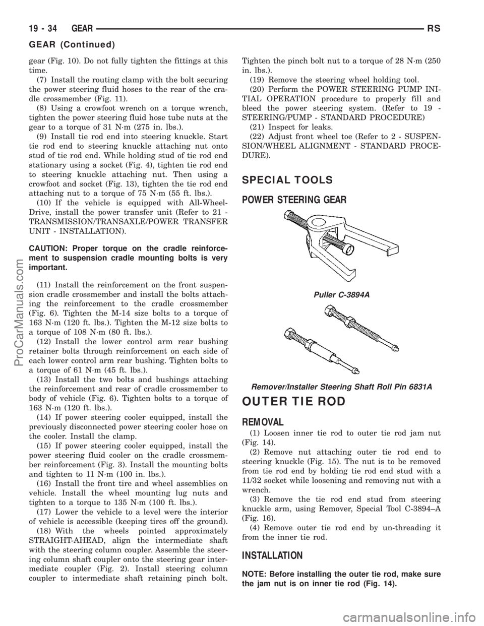
Puller C-3894A
Remover/Installer Steering Shaft Roll Pin 6831A
19 - 34 GEARRS
GEAR (Continued)
ProCarManuals.com
Page 1498 of 2177
INSTALLATION
INSTALLATION - 2.4L GAS
(1) Install modular clutch assembly to transaxle.
Assemble transaxle to engine.
(2) Install and torque transaxle-to-engine bolts to
95 N´m (70 ft. lbs.).
(3) Raise transaxle/engine assembly into position
and install upper mount through-bolt. Torque
through-bolt to 75 N´m (55 ft. lbs.).
(4) Remove screw jack.
(5) Install and torque modular clutch assembly-to-
drive plate bolts to 88 N´m (65 ft. lbs.)
(6) Install structural collar.
(7) Connect back-up lamp switch connector.
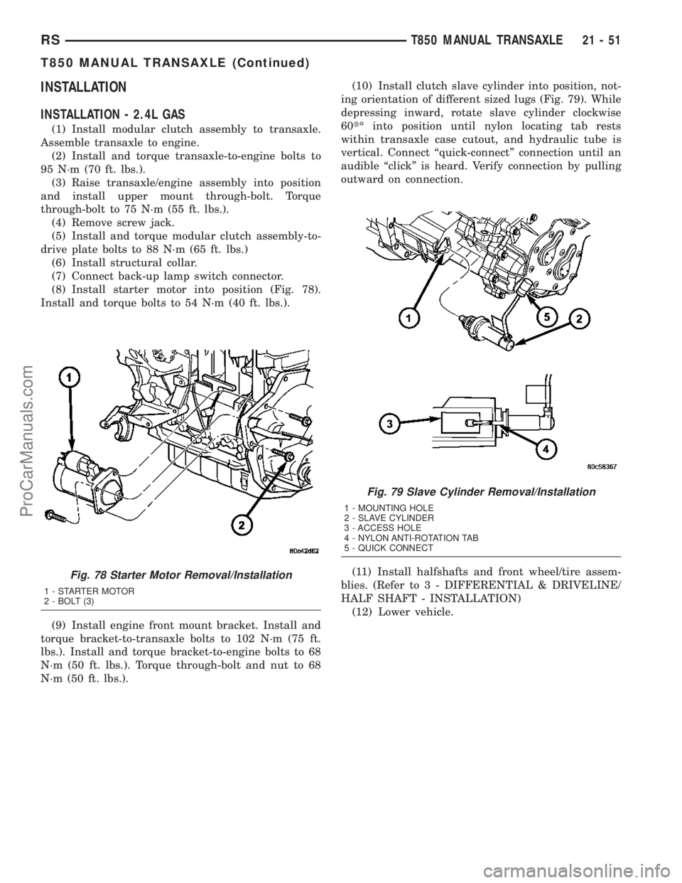
(8) Install starter motor into position (Fig. 78).
Install and torque bolts to 54 N´m (40 ft. lbs.).
(9) Install engine front mount bracket. Install and
torque bracket-to-transaxle bolts to 102 N´m (75 ft.
lbs.). Install and torque bracket-to-engine bolts to 68
N´m (50 ft. lbs.). Torque through-bolt and nut to 68
N´m (50 ft. lbs.).(10) Install clutch slave cylinder into position, not-
ing orientation of different sized lugs (Fig. 79). While
depressing inward, rotate slave cylinder clockwise
60tÉ into position until nylon locating tab rests
within transaxle case cutout, and hydraulic tube is
vertical. Connect ªquick-connectº connection until an
audible ªclickº is heard. Verify connection by pulling
outward on connection.
(11) Install halfshafts and front wheel/tire assem-
blies. (Refer to 3 - DIFFERENTIAL & DRIVELINE/
HALF SHAFT - INSTALLATION)
(12) Lower vehicle.
Fig. 78 Starter Motor Removal/Installation
1 - STARTER MOTOR
2 - BOLT (3)
Fig. 79 Slave Cylinder Removal/Installation
1 - MOUNTING HOLE
2 - SLAVE CYLINDER
3 - ACCESS HOLE
4 - NYLON ANTI-ROTATION TAB
5 - QUICK CONNECT
RST850 MANUAL TRANSAXLE21-51
T850 MANUAL TRANSAXLE (Continued)
ProCarManuals.com
Page 1501 of 2177
(8) Install engine front mount bracket. Install and
torque bracket-to-transaxle bolts to 102 N´m (75 ft.
lbs.). Install and torque bracket-to-engine bolts to 68
N´m (50 ft. lbs.). Torque through-bolt and nut to 68
N´m (50 ft. lbs.).
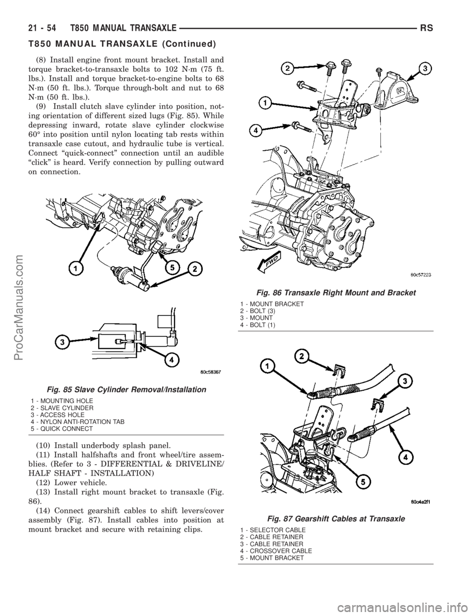
(9) Install clutch slave cylinder into position, not-
ing orientation of different sized lugs (Fig. 85). While
depressing inward, rotate slave cylinder clockwise
60É into position until nylon locating tab rests within
transaxle case cutout, and hydraulic tube is vertical.
Connect ªquick-connectº connection until an audible
ªclickº is heard. Verify connection by pulling outward
on connection.
(10) Install underbody splash panel.
(11) Install halfshafts and front wheel/tire assem-
blies. (Refer to 3 - DIFFERENTIAL & DRIVELINE/
HALF SHAFT - INSTALLATION)
(12) Lower vehicle.
(13) Install right mount bracket to transaxle (Fig.
86).
(14) Connect gearshift cables to shift levers/cover
assembly (Fig. 87). Install cables into position at
mount bracket and secure with retaining clips.
Fig. 85 Slave Cylinder Removal/Installation
1 - MOUNTING HOLE
2 - SLAVE CYLINDER
3 - ACCESS HOLE
4 - NYLON ANTI-ROTATION TAB
5 - QUICK CONNECT
Fig. 86 Transaxle Right Mount and Bracket
1 - MOUNT BRACKET
2 - BOLT (3)
3 - MOUNT
4 - BOLT (1)
Fig. 87 Gearshift Cables at Transaxle
1 - SELECTOR CABLE
2 - CABLE RETAINER
3 - CABLE RETAINER
4 - CROSSOVER CABLE
5 - MOUNT BRACKET
21 - 54 T850 MANUAL TRANSAXLERS
T850 MANUAL TRANSAXLE (Continued)
ProCarManuals.com