2003 CHRYSLER CARAVAN set clock
[x] Cancel search: set clockPage 1244 of 2177
INSTALLATION
INSTALLATION - CRANKSHAFT SPROCKET
CAUTION: The crankshaft sprocket is set to a pre-
determined depth from the factory for correct tim-
ing belt tracking. If removed, use of Special Tool
6792 is required to set the sprocket to original
installation depth. An incorrectly installed sprocket
will result in timing belt and engine damage.
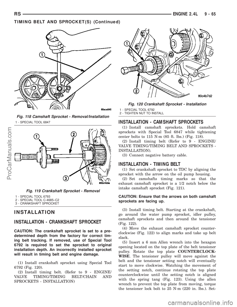
(1) Install crankshaft sprocket using Special Tool
6792 (Fig. 120).
(2) Install timing belt. (Refer to 9 - ENGINE/
VALVE TIMING/TIMING BELT/CHAIN AND
SPROCKETS - INSTALLATION)
INSTALLATION - CAMSHAFT SPROCKETS
(1) Install camshaft sprockets. Hold camshaft
sprockets with Special Tool 6847 while tightening
center bolts to 115 N´m (85 ft. lbs.) (Fig. 118).
(2) Install timing belt (Refer to 9 - ENGINE/
VALVE TIMING/TIMING BELT AND SPROCKETS -
INSTALLATION).
(3) Connect negative battery cable.
INSTALLATION - TIMING BELT
(1) Set crankshaft sprocket to TDC by aligning the
sprocket with the arrow on the oil pump housing.
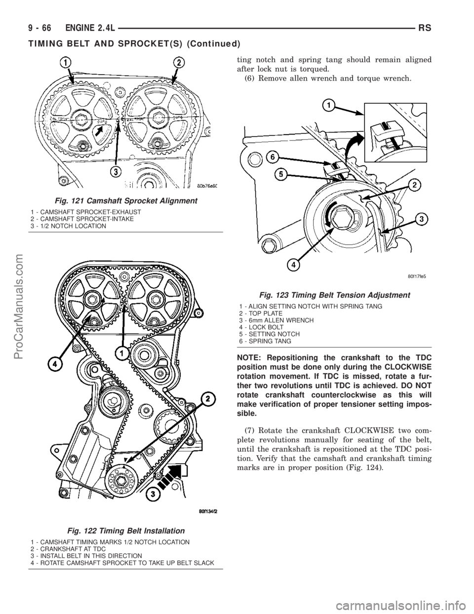
(2) Set camshafts timing marks so that the
exhaust camshaft sprocket is a 1/2 notch below the
intake camshaft sprocket (Fig. 121).
CAUTION: Ensure that the arrows on both camshaft
sprockets are facing up.
(3) Install timing belt. Starting at the crankshaft,
go around the water pump sprocket, idler pulley,
camshaft sprockets and then around the tensioner
(Fig. 122).
(4) Move the exhaust camshaft sprocket counter-
clockwise (Fig. 122) to align marks and take up belt
slack.
(5) Inserta6mmAllen wrench into the hexagon
opening located on the top plate of the belt tensioner
pulley. Rotate the top plateCOUNTERCLOCK-
WISE. The tensioner pulley will move against the
belt and the tensioner setting notch will eventually
start to move clockwise. Watching the movement of
the setting notch, continue rotating the top plate
counterclockwise until the setting notch is aligned
with the spring tang (Fig. 123). Using the allen
wrench to prevent the top plate from moving, torque
the tensioner lock bolt to 25 N´m (220 in. lbs.). Set-
Fig. 118 Camshaft Sprocket - Removal/Installation
1 - SPECIAL TOOL 6847
Fig. 119 Crankshaft Sprocket - Removal
1 - SPECIAL TOOL 6793
2 - SPECIAL TOOL C-4685±C2
3 - CRANKSHAFT SPROCKET
Fig. 120 Crankshaft Sprocket - Installation
1 - SPECIAL TOOL 6792
2 - TIGHTEN NUT TO INSTALL
RSENGINE 2.4L9-65
TIMING BELT AND SPROCKET(S) (Continued)
ProCarManuals.com
Page 1245 of 2177
ting notch and spring tang should remain aligned
after lock nut is torqued.
(6) Remove allen wrench and torque wrench.
NOTE: Repositioning the crankshaft to the TDC
position must be done only during the CLOCKWISE
rotation movement. If TDC is missed, rotate a fur-
ther two revolutions until TDC is achieved. DO NOT
rotate crankshaft counterclockwise as this will
make verification of proper tensioner setting impos-
sible.
(7) Rotate the crankshaft CLOCKWISE two com-
plete revolutions manually for seating of the belt,
until the crankshaft is repositioned at the TDC posi-
tion. Verify that the camshaft and crankshaft timing
marks are in proper position (Fig. 124).
Fig. 121 Camshaft Sprocket Alignment
1 - CAMSHAFT SPROCKET-EXHAUST
2 - CAMSHAFT SPROCKET-INTAKE
3 - 1/2 NOTCH LOCATION
Fig. 122 Timing Belt Installation
1 - CAMSHAFT TIMING MARKS 1/2 NOTCH LOCATION
2 - CRANKSHAFT AT TDC
3 - INSTALL BELT IN THIS DIRECTION
4 - ROTATE CAMSHAFT SPROCKET TO TAKE UP BELT SLACK
Fig. 123 Timing Belt Tension Adjustment
1 - ALIGN SETTING NOTCH WITH SPRING TANG
2 - TOP PLATE
3 - 6mm ALLEN WRENCH
4 - LOCK BOLT
5 - SETTING NOTCH
6 - SPRING TANG
9 - 66 ENGINE 2.4LRS
TIMING BELT AND SPROCKET(S) (Continued)
ProCarManuals.com
Page 1332 of 2177
VALVE TIMING
STANDARD PROCEDURE
STANDARD PROCEDURE - VALVE TIMING
VERIFICATION
(1) Remove front cylinder head cover and all 6
spark plugs.
(2) Rotate engine until the #2 piston is at TDC of
the compression stroke.
(3) Install a degree wheel on the crankshaft pulley.
(4) With proper adaptor, install a dial indicator
into #2 spark plug hole. Using the indicator find TDC
on the compression stroke.
(5) Position the degree wheel to zero.
(6) Remove dial indicator from spark plug hole.
(7) Place a 5.08 mm (0.200 in.) spacer between the
valve stem tip of #2 intake valve and rocker arm pad.
Allow tappet to bleed down to give a solid tappet
effect.
(8) Install a dial indicator so plunger contacts the
#2 intake valve spring retainer as nearly perpendic-
ular as possible. Zero the indicator.
(9) Rotate the engine clockwise until the intake
valve has lifted .254 mm (0.010 in.).
CAUTION: Do not turn crankshaft any further clock-
wise as intake valve might bottom and result in
serious damage.
(10) Degree wheel should read 6 degrees BTDC to
6 degrees ATDC.
STANDARD PROCEDURE - MEASURING
TIMING CHAIN WEAR
NOTE: This procedure must be performed with the
timing chain cover removed (Refer to 9 - ENGINE/
VALVE TIMING/TIMING CHAIN COVER - REMOVAL).
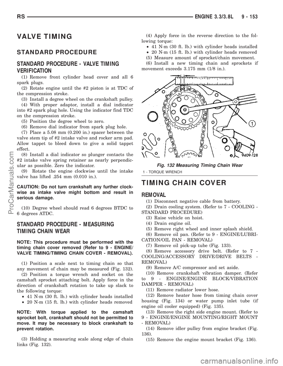
(1) Position a scale next to timing chain so that
any movement of chain may be measured (Fig. 132).
(2) Position a torque wrench and socket on the
camshaft sprocket attaching bolt. Apply force in the
direction of crankshaft rotation to take up slack to
the following torque:
²41 N´m (30 ft. lb.) with cylinder heads installed
²20 N´m (15 ft. lb.) with cylinder heads removed
NOTE: With torque applied to the camshaft
sprocket bolt, crankshaft should not be permitted to
move. It may be necessary to block crankshaft to
prevent rotation.
(3) Holding a measuring scale along edge of chain
links (Fig. 132).(4) Apply force in the reverse direction to the fol-
lowing torque:
²41 N´m (30 ft. lb.) with cylinder heads installed
²20 N´m (15 ft. lb.) with cylinder heads removed
(5) Measure amount of sprocket/chain movement.
(6) Install a new timing chain and sprockets if
movement exceeds 3.175 mm (1/8 in.).
TIMING CHAIN COVER
REMOVAL
(1) Disconnect negative cable from battery.
(2) Drain cooling system. (Refer to 7 - COOLING -
STANDARD PROCEDURE)
(3) Raise vehicle on hoist.
(4) Drain engine oil.
(5) Remove right wheel and inner splash shield.
(6) Remove oil pan. (Refer to 9 - ENGINE/LUBRI-
CATION/OIL PAN - REMOVAL)
(7) Remove oil pick-up tube (Fig. 133).
(8) Remove accessory drive belt. (Refer to 7 -
COOLING/ACCESSORY DRIVE/DRIVE BELTS -
REMOVAL)
(9) Remove A/C compressor and set aside.
(10) Remove crankshaft vibration damper. (Refer
to 9 - ENGINE/ENGINE BLOCK/VIBRATION
DAMPER - REMOVAL)
(11) Remove radiator lower hose.
(12) Remove heater hose from timing chain cover
housing (Fig. 134) or water pump inlet tube (if
engine oil cooler equipped) (Fig. 135).
(13) Remove the right side engine mount. (Refer to
9 - ENGINE/ENGINE MOUNTING/RIGHT MOUNT
- REMOVAL)
(14) Remove idler pulley from engine bracket (Fig.
136).
(15) Remove the engine mount bracket (Fig. 136).
Fig. 132 Measuring Timing Chain Wear
1 - TORQUE WRENCH
RSENGINE 3.3/3.8L9 - 153
ProCarManuals.com
Page 1713 of 2177
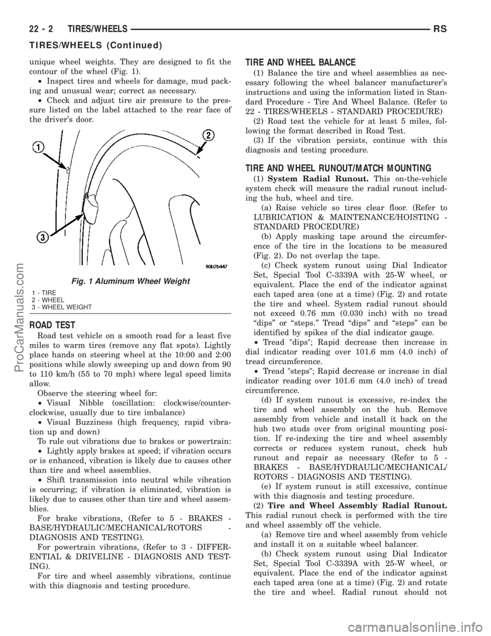
unique wheel weights. They are designed to fit the
contour of the wheel (Fig. 1).
²Inspect tires and wheels for damage, mud pack-
ing and unusual wear; correct as necessary.
²Check and adjust tire air pressure to the pres-
sure listed on the label attached to the rear face of
the driver's door.
ROAD TEST
Road test vehicle on a smooth road for a least five
miles to warm tires (remove any flat spots). Lightly
place hands on steering wheel at the 10:00 and 2:00
positions while slowly sweeping up and down from 90
to 110 km/h (55 to 70 mph) where legal speed limits
allow.
Observe the steering wheel for:
²Visual Nibble (oscillation: clockwise/counter-
clockwise, usually due to tire imbalance)
²Visual Buzziness (high frequency, rapid vibra-
tion up and down)
To rule out vibrations due to brakes or powertrain:
²Lightly apply brakes at speed; if vibration occurs
or is enhanced, vibration is likely due to causes other
than tire and wheel assemblies.
²Shift transmission into neutral while vibration
is occurring; if vibration is eliminated, vibration is
likely due to causes other than tire and wheel assem-
blies.
For brake vibrations, (Refer to 5 - BRAKES -
BASE/HYDRAULIC/MECHANICAL/ROTORS -
DIAGNOSIS AND TESTING).
For powertrain vibrations, (Refer to 3 - DIFFER-
ENTIAL & DRIVELINE - DIAGNOSIS AND TEST-
ING).
For tire and wheel assembly vibrations, continue
with this diagnosis and testing procedure.
TIRE AND WHEEL BALANCE
(1) Balance the tire and wheel assemblies as nec-
essary following the wheel balancer manufacturer's
instructions and using the information listed in Stan-
dard Procedure - Tire And Wheel Balance. (Refer to
22 - TIRES/WHEELS - STANDARD PROCEDURE)
(2) Road test the vehicle for at least 5 miles, fol-
lowing the format described in Road Test.
(3) If the vibration persists, continue with this
diagnosis and testing procedure.
TIRE AND WHEEL RUNOUT/MATCH MOUNTING
(1)System Radial Runout.This on-the-vehicle
system check will measure the radial runout includ-
ing the hub, wheel and tire.
(a) Raise vehicle so tires clear floor. (Refer to
LUBRICATION & MAINTENANCE/HOISTING -
STANDARD PROCEDURE)
(b) Apply masking tape around the circumfer-
ence of the tire in the locations to be measured
(Fig. 2). Do not overlap the tape.
(c) Check system runout using Dial Indicator
Set, Special Tool C-3339A with 25-W wheel, or
equivalent. Place the end of the indicator against
each taped area (one at a time) (Fig. 2) and rotate
the tire and wheel. System radial runout should
not exceed 0.76 mm (0.030 inch) with no tread
ªdipsº or ªsteps.º Tread ªdipsº and ªstepsº can be
identified by spikes of the dial indicator gauge.
²Tread9dips9; Rapid decrease then increase in
dial indicator reading over 101.6 mm (4.0 inch) of
tread circumference.
²Tread9steps9; Rapid decrease or increase in dial
indicator reading over 101.6 mm (4.0 inch) of tread
circumference.
(d) If system runout is excessive, re-index the
tire and wheel assembly on the hub. Remove
assembly from vehicle and install it back on the
hub two studs over from original mounting posi-
tion. If re-indexing the tire and wheel assembly
corrects or reduces system runout, check hub
runout and repair as necessary (Refer to 5 -
BRAKES - BASE/HYDRAULIC/MECHANICAL/
ROTORS - DIAGNOSIS AND TESTING).
(e) If system runout is still excessive, continue
with this diagnosis and testing procedure.
(2)Tire and Wheel Assembly Radial Runout.
This radial runout check is performed with the tire
and wheel assembly off the vehicle.
(a) Remove tire and wheel assembly from vehicle
and install it on a suitable wheel balancer.
(b) Check system runout using Dial Indicator
Set, Special Tool C-3339A with 25-W wheel, or
equivalent. Place the end of the indicator against
each taped area (one at a time) (Fig. 2) and rotate
the tire and wheel. Radial runout should not
Fig. 1 Aluminum Wheel Weight
1 - TIRE
2 - WHEEL
3 - WHEEL WEIGHT
22 - 2 TIRES/WHEELSRS
TIRES/WHEELS (Continued)
ProCarManuals.com
Page 2027 of 2177
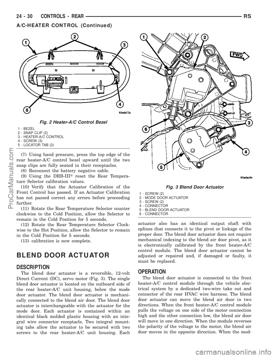
(7) Using hand pressure, press the top edge of the
rear heater-A/C control bezel upward until the two
snap clips are fully seated in their receptacles.
(8) Reconnect the battery negative cable.
(9) Using the DRB-IIItreset the Rear Tempera-
ture Selector calibration values.
(10) Verify that the Actuator Calibration of the
Front Control has passed. If an Actuator Calibration
has not passed correct any errors before proceeding
further.
(11) Rotate the Rear Temperature Selector counter
clockwise to the Cold Position, allow the Selector to
remain in the Cold Position for 5 seconds.
(12) Rotate the Rear Temperature Selector Clock-
wise to the Hot Position, allow the Selector to remain
in the Cold Position for 5 seconds.
(13) calibration is now complete.
BLEND DOOR ACTUATOR
DESCRIPTION
The blend door actuator is a reversible, 12-volt
Direct Current (DC), servo motor (Fig. 3). The single
blend door actuator is located on the outboard side of
the rear heater-A/C unit housing, below the mode
door actuator. The blend door actuator is mechani-
cally connected to the blend air door. The blend door
actuator is interchangeable with the actuator for the
mode door. Each actuator is contained within an
identical black molded plastic housing with an inte-
gral wire connector receptacle. Two integral mount-
ing tabs allow the actuator to be secured with two
screws to the rear heater-A/C unit housing. Eachactuator also has an identical output shaft with
splines that connects it to the pivot or linkage of the
proper door. The blend door actuator does not require
mechanical indexing to the blend air door pivot, as it
is electronically calibrated by the front heater-A/C
control module. The blend door actuator cannot be
adjusted or repaired and, if damaged or faulty, it
must be replaced.OPERATION
The blend door actuator is connected to the front
heater-A/C control module through the vehicle elec-
trical system by a dedicated two-wire take out and
connector of the rear HVAC wire harness. The blend
door actuator can move the blend air door in two
directions. When the front heater-A/C control module
pulls the voltage on one side of the motor connection
high and the other connection low, the blend air door
will move in one direction. When the module reverses
the polarity of the voltage to the motor, the blend air
door moves in the opposite direction. When the mod-
Fig. 2 Heater-A/C Control Bezel
1 - BEZEL
2 - SNAP CLIP (2)
3 - HEATER-A/C CONTROL
4 - SCREW (3)
5 - LOCATOR TAB (2)
Fig. 3 Blend Door Actuator
1 - SCREW (2)
2 - MODE DOOR ACTUATOR
3 - SCREW (2)
4 - CONNECTOR
5 - BLEND DOOR ACTUATOR
6 - CONNECTOR
24 - 30 CONTROLS - REARRS
A/C-HEATER CONTROL (Continued)
ProCarManuals.com
Page 2145 of 2177
CENTER - DESCRIPTION, ELECTRONIC
VEHICLE INFO.......................8M-6
CENTER - DIAGNOSIS AND TESTING,
ELECTRONIC VEHICLE INFORMATION.....8M-7
CENTER - INSTALLATION, ELECTRONIC
VEHICLE INFO.......................8M-9
CENTER - OPERATION, ELECTRONIC
VEHICLE INFO.......................8M-7
CENTER - REMOVAL, ELECTRONIC
VEHICLE INFO.......................8M-9
CENTER BEZEL - INSTALLATION,
INSTRUMENT PANEL..................23-67
CENTER BEZEL - REMOVAL,
INSTRUMENT PANEL..................23-67
CENTER BEZEL OUTLETS -
INSTALLATION.......................24-42
CENTER BEZEL OUTLETS - REMOVAL....24-40
CENTER CONSOLE LAMP SWITCH -
INSTALLATION.......................8L-26
CENTER CONSOLE LAMP SWITCH -
REMOVAL..........................8L-26
CENTER HIGH MOUNTED STOP LAMP -
INSTALLATION........................8L-6
CENTER HIGH MOUNTED STOP LAMP -
REMOVAL...........................8L-6
CENTER HIGH MOUNTED STOP LAMP
UNIT - INSTALLATION..................8L-7
CENTER HIGH MOUNTED STOP LAMP
UNIT - REMOVAL.....................8L-6
CENTER HINGE - INSTALLATION.........23-24
CENTER HINGE - REMOVAL............23-24
CENTER PROGRAMMING - STANDARD
PROCEDURE, ELECTRONIC VEHICLE
INFORMATION.......................8M-7
CENTER STRIKER - INSTALLATION.......23-27
CENTER STRIKER - REMOVAL..........23-27
CENTERING - STANDARD PROCEDURE,
CLOCK SPRING.......................8O-4
CERTIFICATION LABEL - DESCRIPTION,
VEHICLE SAFETY..................Intro.-11
CHAIN AND CAMSHAFT SPROCKET -
INSTALLATION, TIMING................9-157
CHAIN AND CAMSHAFT SPROCKET -
REMOVAL, TIMING...................9-156
CHAIN COVER - INSTALLATION, TIMING . . 9-155
CHAIN COVER - REMOVAL, TIMING......9-153
CHAIN WEAR - STANDARD PROCEDURE,
MEASURING TIMING..................9-153
CHANGE - STANDARD PROCEDURE,
DIFFERENTIAL ASSEMBLY FLUID.........3-40
CHANGE - STANDARD PROCEDURE,
ENGINE OIL AND FILTER...........9-137,9-53
CHANGE - STANDARD PROCEDURE,
OVERRUNNING CLUTCH HOUSING
FLUID..............................3-41
CHANGE - STANDARD PROCEDURE, PTU
FLUID..............................21-5
CHANGER - DESCRIPTION, CD...........8A-7
CHANGER - INSTALLATION, CD..........8A-8
CHANGER - OPERATION, CD.............8A-7
CHANGER - REMOVAL, CD..............8A-8
CHANNEL - INSTALLATION, WATER.....23-118
CHANNEL - REMOVAL, WATER.........23-118
CHARGE - STANDARD PROCEDURE,
REFRIGERANT SYSTEM
...............24-88
CHARGE LEVEL - DIAGNOSIS AND
TESTING, REFRIGERANT SYSTEM
.......24-85
CHARGING - STANDARD PROCEDURE,
CONVENTIONAL BATTERY
..............8F-11
CHARGING - STANDARD PROCEDURE,
SPIRAL PLATE BATTERY
...............8F-10
CHARGING SYSTEM - DESCRIPTION
.....8F-20
CHARGING SYSTEM - OPERATION
.......8F-20
CHARTS - DIAGNOSIS AND TESTING,
STEERING SYSTEM DIAGNOSIS
..........19-3
CHARTS - SPECIFICATIONS, COLOR
CODE
..............................23-83
CHATTER COMPLAINTS - DIAGNOSIS
AND TESTING, CLUTCH
.................6-6
CHECK - DIAGNOSIS AND TESTING,
COOLING SYSTEM FLOW
................7-3
CHECK - DIAGNOSIS AND TESTING,
EXHAUST SYSTEM RESTRICTION
.........11-2
CHECK - STANDARD PROCEDURE,
COOLANT LEVEL
.......................7-5
CHECK - STANDARD PROCEDURE,
ENGINE OIL LEVEL
...................9-137CHECK - STANDARD PROCEDURE, FLUID
LEVEL.............................21-71
CHECK, STANDARD PROCEDURE -
ENGINE OIL LEVEL....................9-53
CHECK, STANDARD PROCEDURE - FLUID
LEVEL AND CONDITION..............21-201
CHECK STRAP - INSTALLATION.........23-15
CHECK STRAP - REMOVAL.............23-15
CHECKING - STANDARD PROCEDURE,
BRAKE FLUID LEVEL...................5-32
CHECKING - STANDARD PROCEDURE,
POWER STEERING FLUID LEVEL........19-44
CHECKING BATTERY ELECTROLYTE
LEVEL - STANDARD PROCEDURE........8F-14
CHECKING ENGINE OIL PRESSURE -
DIAGNOSIS AND TESTING..............9-52
CHECKING POWER STEERING BELT
TENSION - STANDARD PROCEDURE.......7-8
CHILD SEAT - INSTALLATION, QUAD.....23-88
CHILD SEAT - REMOVAL, QUAD.........23-88
CHILD SEAT MODULE, BENCH SEAT -
REMOVAL..........................23-86
CHIME SYSTEM - DIAGNOSIS AND
TESTING............................8B-1
CHIME/BUZZER - DESCRIPTION..........8B-1
CHIME/BUZZER - OPERATION............8B-1
CHIME/BUZZER - WARNING.............8B-1
CHIME/THERMISTOR - DESCRIPTION....8N-10
CHIME/THERMISTOR - INSTALLATION....8N-10
CHIME/THERMISTOR - OPERATION......8N-10
CHIME/THERMISTOR - REMOVAL.......8N-10
CHIRP PREFERENCE - STANDARD
PROCEDURE, HORN..................8N-42
CIRCUIT - DIAGNOSIS AND TESTING,
AMBIENT TEMPERATURE SENSOR......8M-12
CIRCUIT FUNCTIONS - DESCRIPTION . . 8W-01-6
CIRCUIT INFORMATION - DESCRIPTION . 8W-01-5
CIRCUIT RESISTANCE TEST -
DIAGNOSIS AND TESTING, FEED........8F-32
CIRCUIT TEST - DIAGNOSIS AND
TESTING, CONTROL..................8F-30
CIRCUIT TEST - DIAGNOSIS AND
TESTING, FEED......................8F-33
CIRCUITS - OPERATION, NON-
MONITORED.........................25-5
CIRCUITS AND VALVES - OPERATION,
HYDRAULIC..........................5-83
CLAMP - STANDARD PROCEDURE,
HOSES..............................14-6
CLAMPS - DESCRIPTION, FUEL
LINES/HOSES........................14-6
CLAMPS - DESCRIPTION, HOSE...........7-1
CLAMPS - OPERATION, HOSE.............7-2
CLEAN, CLEANING...................21-114
CLEARANCE - STANDARD PROCEDURE,
MEASURING CONNECTING ROD
BEARING...........................9-120
CLEARANCE USING PLASTIGAGE -
STANDARD PROCEDURE, MEASURING
BEARING........................9-12,9-84
CLOCK SPRING - DESCRIPTION..........8O-4
CLOCK SPRING - INSTALLATION.........8O-5
CLOCK SPRING - OPERATION...........8O-4
CLOCK SPRING - REMOVAL.............8O-4
CLOCK SPRING CENTERING -
STANDARD PROCEDURE...............8O-4
CLUSTER - DESCRIPTION, INSTRUMENT . . . 8J-1
CLUSTER - OPERATION, INSTRUMENT.....8J-1
CLUSTER BEZEL - INSTALLATION
........23-62
CLUSTER BEZEL - REMOVAL
...........23-62
CLUSTER DIAGNOSIS - DIAGNOSIS AND
TESTING
............................8J-2
CLUSTER ILLUMINATION LAMPS -
INSTALLATION
.......................8L-26
CLUSTER ILLUMINATION LAMPS -
REMOVAL
..........................8L-26
CLUSTER LENS - INSTALLATION
........8J-10
CLUSTER LENS - REMOVAL
............8J-10
CLUTCH - DESCRIPTION
.................6-1
CLUTCH - DESCRIPTION, BI-
DIRECTIONAL OVERRUNNING
...........3-34
CLUTCH - DESCRIPTION, COMPRESSOR
. . 24-16
CLUTCH - OPERATION, BI-DIRECTIONAL
OVERRUNNING
.......................3-36
CLUTCH - OPERATION, COMPRESSOR
....24-17
CLUTCH AIR GAP - STANDARD
PROCEDURE, COMPRESSOR
...........24-17CLUTCH AIR PRESSURE TESTS -
DIAGNOSIS AND TESTING............21-122
CLUTCH ASSEMBLY - ASSEMBLY, INPUT . 21-216
CLUTCH ASSEMBLY - DISASSEMBLY,
INPUT............................21-208
CLUTCH ASSY - 2.4L GAS -
INSTALLATION, MODULAR..............6-11
CLUTCH ASSY - 2.4L GAS - REMOVAL,
MODULAR...........................6-11
CLUTCH BREAK-IN - STANDARD
PROCEDURE, COMPRESSOR...........24-17
CLUTCH CHATTER COMPLAINTS -
DIAGNOSIS AND TESTING...............6-6
CLUTCH COIL - DIAGNOSIS AND
TESTING, COMPRESSOR...............24-20
CLUTCH COVER AND DISC RUNOUT -
DIAGNOSIS AND TESTING...............6-6
CLUTCH DISC AND PRESSURE PLATE -
2.5L TD - INSTALLATION...............6-12
CLUTCH DISC AND PRESSURE PLATE -
2.5L TD - REMOVAL...................6-11
CLUTCH HOUSING FLUID CHANGE -
STANDARD PROCEDURE,
OVERRUNNING.......................3-41
CLUTCH PEDAL INTERLOCK SWITCH -
INSTALLATION........................6-14
CLUTCH PEDAL INTERLOCK SWITCH -
REMOVAL...........................6-13
CLUTCH PEDAL UPSTOP SWITCH -
INSTALLATION........................6-16
CLUTCH PEDAL UPSTOP SWITCH -
REMOVAL...........................6-15
CLUTCH RELAY - DESCRIPTION,
COMPRESSOR........................24-21
CLUTCH RELAY - DIAGNOSIS AND
TESTING, COMPRESSOR...............24-22
CLUTCH RELAY - INSTALLATION,
COMPRESSOR.......................24-22
CLUTCH RELAY - OPERATION,
COMPRESSOR.......................24-21
CLUTCH RELAY - REMOVAL,
COMPRESSOR.......................24-22
CLUTCH RELEASE LEVER AND BEARING
- INSTALLATION.......................6-7
CLUTCH RELEASE LEVER AND BEARING
- REMOVAL...........................6-6
CLUTCH SYSTEM - DIAGNOSIS AND
TESTING.............................6-3
CLUTCH/COIL - INSPECTION,
COMPRESSOR.......................24-18
CLUTCHES - DESCRIPTION, DRIVING....21-190
CLUTCHES - DESCRIPTION, HOLDING . . . 21-207
CLUTCHES - OPERATION, DRIVING.....21-190
CLUTCHES - OPERATION, HOLDING.....21-207
COAT/CLEARCOAT FINISH -
DESCRIPTION, BASE..................23-84
CODE - DESCRIPTION, PAINT...........23-84
CODE CHARTS - SPECIFICATIONS,
COLOR.............................23-83
CODE PLATE - DESCRIPTION, BODY....Intro.-1
CODES - STANDARD PROCEDURE,
ERASING TRANSMITTER..............8M-11
CODES - STANDARD PROCEDURE,
OBTAINING DIAGNOSTIC TROUBLE......8E-15
CODES - STANDARD PROCEDURE,
SETTING TRANSMITTER..............8M-11
COIL - DESCRIPTION, IGNITION
..........8I-6
COIL - DIAGNOSIS AND TESTING,
COMPRESSOR CLUTCH
...............24-20
COIL - OPERATION, IGNITION
............8I-6
COLLAR - INSTALLATION, STRUCTURAL
. . . 9-48
COLLAR - REMOVAL, STRUCTURAL
.......9-47
COLOR CODE CHARTS -
SPECIFICATIONS
.....................23-83
COLUMN - DESCRIPTION, STEERING
.....19-10
COLUMN - DIAGNOSIS AND TESTING,
STEERING
..........................19-12
COLUMN COVER - INSTALLATION,
LOWER STEERING
...................23-69
COLUMN COVER - INSTALLATION, OVER
STEERING
..........................23-69
COLUMN COVER - REMOVAL, LOWER
STEERING
..........................23-69
COLUMN COVER - REMOVAL, OVER
STEERING
..........................23-69
COLUMN COVER BACKING PLATE -
INSTALLATION, STEERING
.............23-69
6 INDEXRS
Description Group-Page Description Group-Page Description Group-Page
ProCarManuals.com