2003 CHRYSLER CARAVAN airbag off
[x] Cancel search: airbag offPage 545 of 2177

SWITCH
DESCRIPTION
There are two separate switch pods that operate
the speed control system and are located on the
steering wheel.
OPERATION
The speed control system has five separate resis-
tive switches that provide a single multiplexed
(MUX) voltage inputs to the PCM.The switch names
are: ON, OFF, SET, COAST, RESUME, ACCEL, TAP-
UP, COAST, and CANCEL. Based on conditions when
the buttons are pushed (and released), the five volt-
ages ranges provided to the PCM result in the follow-
ing functions: ON, OFF, SET, COAST, RESUME,
ACCEL, TAP-UP, TAP-DOWN, COAST, and CAN-
CEL. Refer to the Speed Control Section for more
information
Also the PCM receives an input from the brake
switch to sense whether the brake pedal has been
depressed. When the PCM receives the brake
depressed input, it turns off power to the speed con-
trol servo and disengages speed control. Also the
power to the servo is supplied through the brake
switch, which opens the circuit when the brake pedal
is depressed.
The individual switches cannot be repaired. If one
switch fails, the entire switch module must be
replaced.
REMOVAL
The speed control switches are mounted in the
steering wheel and wired through the clock spring
device under the airbag module.
WARNING: IF REMOVAL OF AIRBAG MODULE IS
NECESSARY, REFER TO THE RESTRAINT SYS-
TEMS SECTION FOR MORE INFORMATION.
(1) Remove the negative battery cable.
(2) Turn off ignition.
(3) Remove the air bag, refer to the restraint sec-
tion for more information.
(4) Remove the screw from bottom of the switch.
(5) Remove switch from steering wheel.
(6) Disconnect two-way electrical connector.
(7) Repeat for the other switch.
INSTALLATION
The speed control switches are mounted in the
steering wheel and wired through the clock spring
device under the airbag module.WARNING: IF REMOVAL OF AIRBAG MODULE IS
NECESSARY, REFER TO THE RESTRAINT SYS-
TEMS SECTION FOR MORE INFORMATION.
(1) Connect two-way electrical connector.
(2) Install switch.
(3) Install screw for the switch.
(4) Repeat for the other switch.
(5) Install the air bag, refer to the restraint section
for more information.
(6) Install the negative battery cable.
VACUUM RESERVOIR
DESCRIPTION
The vacuum reservoir is located in the engine com-
partment. It is made of plastic.
OPERATION
The reservoir stores engine vacuum. Manifold vac-
uum is supplied from the brake booster check valve.
The speed control vacuum supply hose has a check
valve at the source (brake booster) to maintain the
highest available vacuum level in the servo, reservoir
and vacuum hoses. When engine vacuum drops, as in
climbing a grade while driving, the reservoir supplies
the vacuum needed to maintain proper speed control
operation. The vacuum reservoir cannot be repaired
and must be replaced if faulty.
REMOVAL
(1) Release hood latch and open hood.
(2) Disconnect the negative battery cable.
(3) Disconnect the vacuum line to the battery tray/
vacuum reservoir.
(4) Remove battery tray/vacuum reservoir, refer to
the Battery section for more information.
INSTALLATION
(1) Install battery tray/vacuum reservoir, refer to
the Battery section for more information.
(2) Connect vacuum line that leads to the battery
tray/vacuum reservoir.
(3) Connect the negative battery cable.
8P - 6 SPEED CONTROLRS
ProCarManuals.com
Page 588 of 2177

8W-02 COMPONENT INDEX
Component Page
A/C Compressor Clutch Relay............. 8W-42
A/C Compressor Clutch.................. 8W-42
A/C-Heater Control..................... 8W-42
A/C Pressure Sensor.................... 8W-42
Accelerator Pedal Position Sensor.......... 8W-30
Accessory Relay........................ 8W-10
Adjustable Pedals Module................ 8W-30
Adjustable Pedals Relay................. 8W-30
Adjustable Pedals Switch................. 8W-30
Airbag Control Module.................. 8W-43
Ambient Temperature Sensor.............. 8W-49
Antenna............................. 8W-47
ATC Remote Sensor..................... 8W-42
Auto Shut Down Relay.................. 8W-30
Auto Temp Control..................... 8W-42
Automatic Day/Night Mirror.............. 8W-49
Back-Up Lamp Switch................... 8W-51
Battery Temperature Sensor.............. 8W-20
Battery.............................. 8W-20
Blend Door Actuators................... 8W-42
Blower Motor Resistor................... 8W-42
Body Control Module.................... 8W-45
Boost Pressure Sensor................... 8W-30
B-Pillar Switches....................... 8W-61
Brake Fluid Level Switch................ 8W-40
Brake Lamp Switch.................. 8W-30, 51
Brake Transmission Shift Interlock Solenoid . . 8W-31
Cabin Heater Assist..................... 8W-30
Camshaft Position Sensor................ 8W-30
CD Changer.......................... 8W-47
Center Dome Lamp..................... 8W-44
Center High Mounted Stop Lamp........... 8W-51
Cinch/Release Motors................... 8W-61
Clockspring................ 8W-30, 33, 41, 43, 47
Clutch Pedal Interlock Switch.......... 8W-10, 30
Clutch Pedal Upstop Switch............... 8W-30
Combination Relays..................... 8W-54
Controller Antilock Brake................ 8W-35
Crank Case Ventilation Heater............ 8W-30
Crankshaft Position Sensor............... 8W-30
Cylinder Lock Switches.................. 8W-39
Data Link Connector.................... 8W-18
Defogger Relay........................ 8W-48
Door Ajar Switches..................... 8W-39
Door Lock Motor/Ajar Switches............ 8W-61
Door Courtesy Lamps................... 8W-44
Door Lock Switches..................... 8W-61
Dosing Pump......................... 8W-30
Driver Airbag Squibs.................... 8W-43
Driver Seat Belt Switch.................. 8W-43
DVD Screen.......................... 8W-47
DVD/CD Changer...................... 8W-47
ECM/PCM Relay....................... 8W-30
EGR Solenoid......................... 8W-30
Electronic Control Unit.................. 8W-64
Engine Control Module.................. 8W-30
Component Page
Engine Coolant Temp Sensor.............. 8W-30
Engine Oil Pressure Sensor............... 8W-30
Engine Oil Pressure Switch............... 8W-30
EVAP/Purge Solenoid.................... 8W-30
Evaporator Temperature Sensor............ 8W-42
Floor Console Lamp..................... 8W-44
Floor Console Power Outlet............... 8W-41
Fog Lamps........................... 8W-50
Front Blower Module.................... 8W-42
Front Blower Motor Relay................ 8W-42
Front Blower Motor..................... 8W-42
Front Cigar Lighter..................... 8W-41
Front Control Module................... 8W-10
Front Fog Lamp Relay................... 8W-50
Front Intrusion Sensor.................. 8W-39
Front Reading Lamps/Switch.............. 8W-44
Front Washer Pump Motor............... 8W-53
Front Wiper High/Low Relay.............. 8W-53
Front Wiper On/Off Relay................ 8W-53
Fuel Heater Relay...................... 8W-30
Fuel Heater.......................... 8W-30
Fuel Injectors......................... 8W-30
Fuel Pressure Sensor.................... 8W-30
Fuel Pressure Solenoid.................. 8W-30
Fuel Pump Module..................... 8W-30
Fuel Pump Relay....................... 8W-30
Full Open Switches..................... 8W-61
Fuses............................... 8W-10
Fuselink............................. 8W-10
Grounds............................. 8W-15
Generator............................ 8W-20
Glow Plugs........................... 8W-30
Glow Plug Relay....................... 8W-30
Headlamp Leveling Motors............... 8W-50
Headlamp Switch...................... 8W-50
Headlamp Washer Pump Motor............ 8W-53
Headlamp Washer Relay................. 8W-53
Headlamps........................... 8W-50
Heated Seat Backs..................... 8W-63
Heated Seat Cushions................... 8W-63
Heated Seat Modules.................... 8W-63
High Beam Lamps...................... 8W-50
Hood Ajar Switch...................... 8W-39
Horn Relay........................... 8W-41
Horn Switch.......................... 8W-41
Horns............................... 8W-41
Idle Air Control Motor................... 8W-30
Ignition Coil.......................... 8W-30
Ignition Switch........................ 8W-10
Inlet Air Temperature Sensor.............. 8W-30
Input Speed Sensor..................... 8W-31
Instrument Cluster..................... 8W-40
Instrument Panel Switch Bank.... 8W-44, 52, 53, 63
Integrated Power Module................. 8W-10
Knock Sensor......................... 8W-30
Lamp Assemblies...................... 8W-51
RS8W-02 COMPONENT INDEX8W-02-1
ProCarManuals.com
Page 590 of 2177

8W-10 POWER DISTRIBUTION
Component Page
A/C Compressor Clutch . . . 8W-10-22, 24, 47, 48, 51
A/C Compressor Clutch
Relay............ 8W-10-22, 24, 46, 47, 48, 51
Accessory Relay............... 8W-10-16, 31, 68
Adjustable Pedals Relay.............. 8W-10-50
Airbag Control Module............ 8W-10-67, 72
Ambient Temperature Sensor.......... 8W-10-65
Auto Shut Down Relay......... 8W-10-21, 42, 43
Auto Temp Control.................. 8W-10-41
Back-Up Lamp Switch............... 8W-10-69
Battery............ 8W-10-13, 14, 15, 42, 43, 51
Blower Motor Resistor............ 8W-10-19, 39
Body Control Module.... 8W-10-25, 41, 47, 48, 52,
53, 55, 57, 58, 59, 60, 72
Brake Fluid Level Switch............. 8W-10-68
Brake Lamp Switch........... 8W-10-26, 55, 70
Brake Transmission Shift Interlock
Solenoid........................ 8W-10-66
Cabin Heater Assist........... 8W-10-23, 45, 63
Camshaft Position Sensor............. 8W-10-46
Center High Mounted Stop Lamp....... 8W-10-70
Clockspring........................ 8W-10-64
Clutch Pedal Interlock
Switch.............. 8W-10-18, 38, 57, 58, 64
Controller Antilock
Brake...... 8W-10-18, 25, 37, 38, 53, 59, 65, 70
Crank Case Ventilation Heater......... 8W-10-52
Data Link Connector........... 8W-10-36, 65, 72
Defogger Relay............ 8W-10-19, 20, 40, 67
Driver Door Lock Switch........ 8W-10-33, 34, 35
Driver Heated Seat Module........... 8W-10-53
Driver Power Seat Switch............ 8W-10-53
Driver Power Window Switch....... 8W-10-34, 35
DVD/DV Changer................... 8W-10-41
ECM/PCM Relay................. 8W-10-23, 45
EGR Solenoid................... 8W-10-46, 50
Engine Control
Module . . 8W-10-18, 23, 24, 38, 45, 46, 51, 65, 70
Floor Console Lamp................. 8W-10-32
Floor Console Power Outlet........ 8W-10-32, 36
Front Blower Module................ 8W-10-19
Front Blower Module................ 8W-10-39
Front Blower Motor Relay.... 8W-10-18, 19, 39, 67
Front Cigar Lighter.............. 8W-10-16, 32
Front Control Module....... 8W-10-15, 16, 17, 18,
19, 20, 22, 24, 26, 27,
28, 29, 30, 31, 36, 40,
47, 48, 50, 51, 56, 57,
58, 61, 62, 63, 64, 65,
66, 67, 68, 69, 70, 72
Front Fog Lamp Relay......... 8W-10-15, 27, 67
Front Washer Pump Motor...... 8W-10-16, 31, 72Component Page
Front Wiper High/Low Relay.... 8W-10-16, 30, 68
Front Wiper On/Off Relay....... 8W-10-16, 30, 63
Fuel Heater....................... 8W-10-52
Fuel Heater Relay............. 8W-10-24, 51, 68
Fuel Injector No. 1.................. 8W-10-44
Fuel Injector No. 2.................. 8W-10-44
Fuel Injector No. 3.................. 8W-10-44
Fuel Injector No. 4.................. 8W-10-44
Fuel Injector No. 5.................. 8W-10-44
Fuel Injector No. 6.................. 8W-10-44
Fuel Pressure Solenoid............... 8W-10-46
Fuel Pump Module............ 8W-10-22, 47, 48
Fuel Pump Relay........... 8W-10-22, 47, 48, 68
Fuse 1...................... 8W-10-15, 16, 27
Fuse 2...................... 8W-10-15, 28, 29
Fuse 3...................... 8W-10-15, 28, 29
Fuse 4................... 8W-10-15, 16, 17, 30
Fuse 5......................... 8W-10-16, 31
Fuse 6......................... 8W-10-16, 31
Fuse 8......................... 8W-10-17, 36
Fuse 9................ 8W-10-17, 18, 19, 37, 38
Fuse 10........................ 8W-10-19, 39
Fuse 11........................ 8W-10-16, 31
Fuse 12........................ 8W-10-19, 39
Fuse 13........................ 8W-10-20, 40
Fuse 14............... 8W-10-20, 21, 23, 40, 63
Fuse 15...... 8W-10-20, 21, 22, 23, 24, 42, 43, 45
Fuse 16............... 8W-10-21, 23, 42, 43, 45
Fuse 17......... 8W-10-21, 22, 23, 24, 47, 48, 51
Fuse 18............ 8W-10-22, 24, 25, 47, 48, 51
Fuse 19.................. 8W-10-22, 24, 26, 53
Fuse 20........................ 8W-10-25, 53
Fuse 21........................ 8W-10-25, 53
Fuse 22........................ 8W-10-25, 53
Fuse 23..................... 8W-10-25, 57, 58
Fuse 24........................ 8W-10-25, 55
Fuse 26..................... 8W-10-25, 26, 55
Fuse 27........................ 8W-10-26, 55
Fuse 28........................ 8W-10-16, 31
Fuse 30........................ 8W-10-26, 56
Fuse 31........................ 8W-10-26, 56
Fuse 32........................ 8W-10-26, 56
Fuse 33........................ 8W-10-16, 31
Fuselink....................... 8W-10-13, 14
G100............................. 8W-10-59
G101....................... 8W-10-42, 43, 51
G103............................. 8W-10-72
G300.......................... 8W-10-61, 62
Generator................ 8W-10-13, 14, 44, 46
Glow Plug Relay................. 8W-10-13, 46
Headlamp Switch................ 8W-10-29, 66
Headlamp Washer Pump Motor..... 8W-10-26, 56
RS8W-10 POWER DISTRIBUTION8W-10-1
ProCarManuals.com
Page 1407 of 2177
WARNING: THE AIR BAG SYSTEM IS A SENSITIVE,
COMPLEX ELECTRO-MECHANICAL UNIT. BEFORE
ATTEMPTING TO DIAGNOSE, REMOVE OR INSTALL
THE AIR BAG SYSTEM COMPONENTS YOU MUST
FIRST DISCONNECT AND ISOLATE THE BATTERY
NEGATIVE (GROUND) CABLE. THEN WAIT TWO
MINUTES FOR THE SYSTEM CAPACITOR TO DIS-
CHARGE. FAILURE TO DO SO COULD RESULT IN
ACCIDENTAL DEPLOYMENT OF THE AIR BAG AND
POSSIBLE PERSONAL INJURY. THE FASTENERS,
SCREWS, AND BOLTS, ORIGINALLY USED FOR
THE AIR BAG COMPONENTS, HAVE SPECIAL
COATINGS AND ARE SPECIFICALLY DESIGNED
FOR THE AIR BAG SYSTEM. THEY MUST NEVER
BE REPLACED WITH ANY SUBSTITUTES. ANYTIME
A NEW FASTENER IS NEEDED, REPLACE WITH
THE CORRECT FASTENERS PROVIDED IN THE
SERVICE PACKAGE OR FASTENERS LISTED IN
THE PARTS BOOKS.
WARNING: SAFETY GOGGLES SHOULD BE WORN
AT ALL TIMES WHEN WORKING ON STEERING
COLUMNS.
CAUTION: Disconnect negative (ground) cable from
the battery before servicing any column compo-
nent.
CAUTION: Do not attempt to remove the pivot pins
to disassemble the tilting mechanism. Damage will
occur.
DIAGNOSIS AND TESTING - STEERING
COLUMN
For diagnosis of conditions relating to the steering
column (Refer to 19 - STEERING - DIAGNOSIS AND
TESTING) and (Refer to 19 - STEERING - DIAGNO-
SIS AND TESTING).
REMOVAL
NOTE: Before proceeding, (Refer to 19 - STEERING/
COLUMN - WARNING).
(1) Make sure the front wheels of the vehicle are
in the STRAIGHT AHEAD position before beginning
the column removal procedure.
(2) Disconnect negative (ground) cable from the
battery and isolate cable from battery terminal.
(3) Remove the lower shroud (Refer to 19 -
STEERING/COLUMN/LOWER SHROUD - REMOV-
AL).
(4) Remove the traction off switch.
(5) Remove the upper shroud.
(6) Remove the cluster trim bezel (Refer to 23 -
BODY/INSTRUMENT PANEL/CLUSTER BEZEL -
REMOVAL).
(7) Remove the knee blocker (Refer to 23 - BODY/
INSTRUMENT PANEL/STEERING COLUMN
OPENING COVER - REMOVAL).
(8) Remove the parking brake handle link.
(9) Remove the knee blocker reinforcement (Refer
to 23 - BODY/INSTRUMENT PANEL/KNEE
BLOCKER - REMOVAL).
(10) Remove the airbag (Refer to 8 - ELECTRI-
CAL/RESTRAINTS/DRIVER AIRBAG - REMOVAL).
(11) Remove the steering wheel retaining nut.
(12) Remove the vibration damper weight.
(13) Remove the steering wheel (Refer to 19 -
STEERING/COLUMN/STEERING WHEEL -
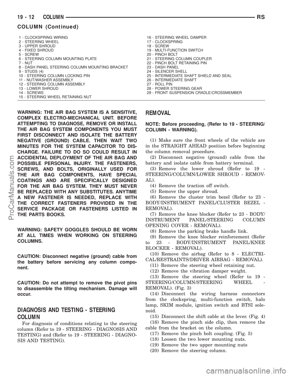
REMOVAL). (Fig. 3)
(14) Disconnect the wiring harness connectors
from the clockspring, multi-function switch, halo
lamp, SKIM module, ignition switch and BTSI sole-
noid.
(15) Disconnect the shift cable at the lever. (Fig. 4)
(16) Remove the pinch side clip, then remove the
cable from the bracket on the column.
(17) Remove the pinch bolt coupling. (Fig. 5)
(18) Loosen the two lower mounting nuts.
(19) Remove the two upper mounting nuts
(20) Remove the steering column.
1 - CLOCKSPRING WIRING
2 - STEERING WHEEL
3 - UPPER SHROUD
4 - FIXED SHROUD
5 - SCREW
6 - STEERING COLUMN MOUNTING PLATE
7 - NUT
8 - DASH PANEL STEERING COLUMN MOUNTING BRACKET
9 - STUDS (4)
10 - STEERING COLUMN LOCKING PIN
11 - NUT/WASHER ASSEMBLY
12 - STEERING COLUMN ASSEMBLY
13 - LOWER SHROUD
14 - SCREWS
15 - STEERING WHEEL RETAINING NUT16 - STEERING WHEEL DAMPER
17 - CLOCKSPRING
18 - SCREW
19 - MULTI-FUNCTION SWITCH
20 - PINCH BOLT
21 - STEERING COLUMN COUPLER
22 - PINCH BOLT RETAINING PIN
23 - DASH PANEL
24 - SILENCER SHELL
25 - INTERMEDIATE SHAFT SHIELD AND SEAL
26 - INTERMEDIATE SHAFT
27 - ROLL PIN
28 - POWER STEERING GEAR
29 - FRONT SUSPENSION CRADLE/CROSSMEMBER
19 - 12 COLUMNRS
COLUMN (Continued)
ProCarManuals.com
Page 1409 of 2177
(10) Install the coupling onto the intermediate
shaft and install the pinch bolt. Tighten the pinch
bolt to 28 N´m (250 in. lbs.).
(11) Install the cable from the bracket on the col-
umn, then install the pinch side clips.
(12) Reconnect the shift cable at the lever.
(13) Reconnect the wiring harness connectors to
the clockspring, multi-function switch, halo lamp,
SKIM module, ignition switch and BTSI solenoid.
(14) Install the steering wheel (Refer to 19 -
STEERING/COLUMN/STEERING WHEEL -
INSTALLATION).
(15) Install the vibration damper weight.
(16) Install the steering wheel retaining nut.
Tighten the nut to 61 N´m (45 ft. lbs.)
(17) Install the airbag (Refer to 8 - ELECTRICAL/
RESTRAINTS/DRIVER AIRBAG - INSTALLATION).
(18) Install the knee blocker reinforcement (Refer
to 23 - BODY/INSTRUMENT PANEL/KNEE
BLOCKER - INSTALLATION).
(19) Install the parking brake handle link.
(20) Install the knee blocker (Refer to 23 - BODY/
INSTRUMENT PANEL/STEERING COLUMN
OPENING COVER - INSTALLATION).
(21) Install the cluster trim bezel (Refer to 23 -
BODY/INSTRUMENT PANEL/CLUSTER BEZEL -
INSTALLATION).
(22) Install the upper shroud (Refer to 19 -
STEERING/COLUMN/LOWER SHROUD - INSTAL-
LATION).
(23) Install the traction off switch.
(24) Install the lower shroud.
SPECIFICATIONS
COLUMN TORQUE
DESCRIPTION N´mFt.
Lbs.In.
Lbs.
Driver Airbag Attaching Bolts 10 Ð 90
Steering Column Coupling
Pinch Bolt28 Ð 250
Steering Column Mounting
Nuts12 Ð 105
Steering Wheel Retaining
Nut61 45 Ð
IGNITION SWITCH
REMOVAL
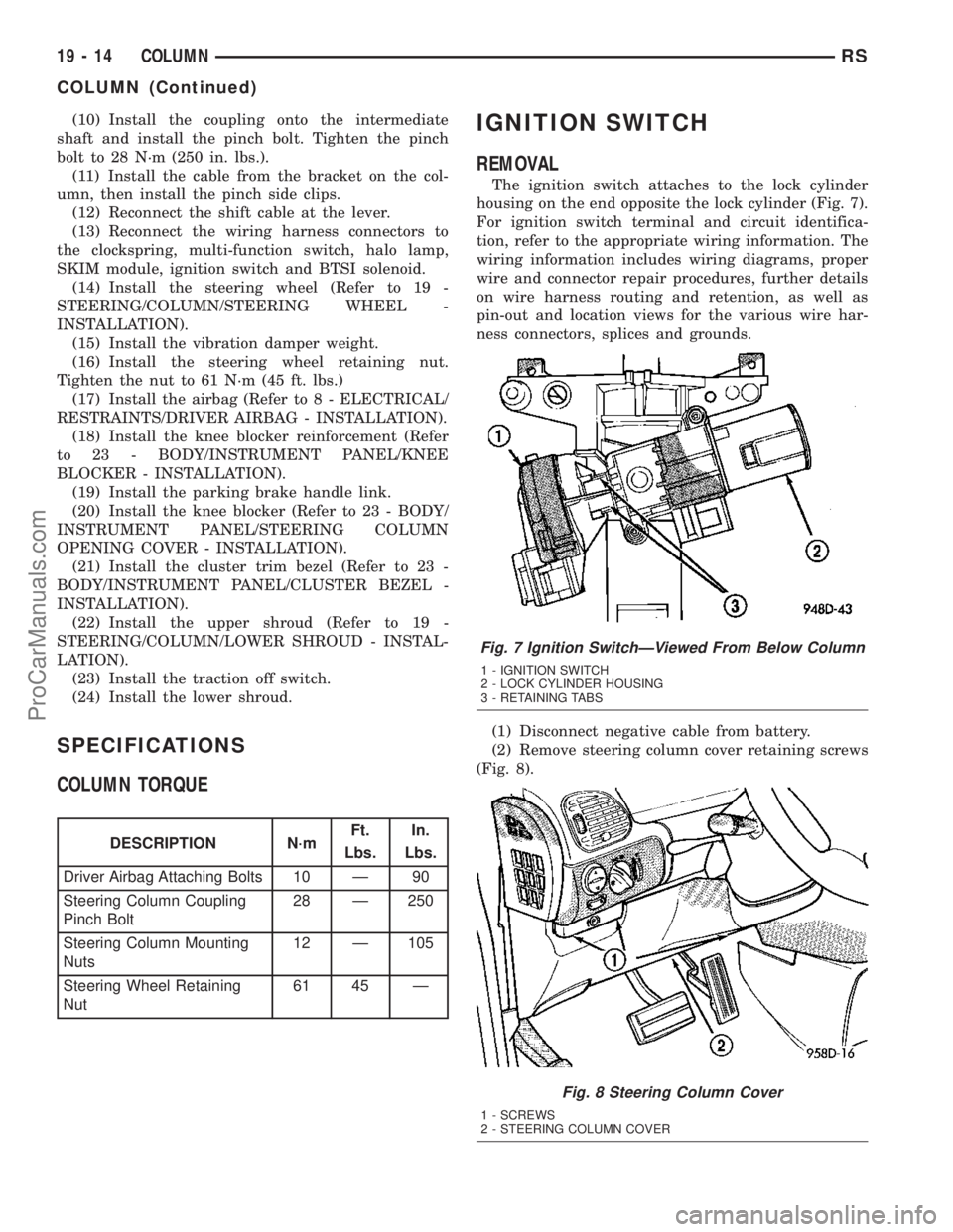
The ignition switch attaches to the lock cylinder
housing on the end opposite the lock cylinder (Fig. 7).
For ignition switch terminal and circuit identifica-
tion, refer to the appropriate wiring information. The
wiring information includes wiring diagrams, proper
wire and connector repair procedures, further details
on wire harness routing and retention, as well as
pin-out and location views for the various wire har-
ness connectors, splices and grounds.
(1) Disconnect negative cable from battery.
(2) Remove steering column cover retaining screws
(Fig. 8).
Fig. 7 Ignition SwitchÐViewed From Below Column
1 - IGNITION SWITCH
2 - LOCK CYLINDER HOUSING
3 - RETAINING TABS
Fig. 8 Steering Column Cover
1 - SCREWS
2 - STEERING COLUMN COVER
19 - 14 COLUMNRS
COLUMN (Continued)
ProCarManuals.com
Page 1418 of 2177
SHROUD - UPPER
REMOVAL
(1) Remove the two shroud-to-shroud mounting
screws from the lower shroud (Fig. 32).
(2) Unsnap the upper shroud from the lower on
the left side as follows:
(a) Hook a finger on the left hand around the
rear of the shrouds at the seam (Fig. 33), near the
snap points.
(b) Grasp the upper shroud at the rear using the
right hand (Fig. 33).
(c) As the left hand's hooked finger is pulled out-
ward against the seam, pull the upper shroud
upward using the right hand, disconnecting the
shroud snaps.
(3) Unsnap the upper shroud from the lower on
the right side as follows:
(a) Hook a finger on the right hand around the
rear of the shrouds at the seam (Fig. 34), near the
snap points.
(b) Grasp the upper shroud at the rear using the
left hand (Fig. 34).
(c) As the right hand's hooked finger is pulled
outward against the seam, pull the upper shroud
upward using the left hand, disconnecting the
shroud snaps.
(4) Lift the upper shroud straight up off the steer-
ing column. If vehicle is equipped with traction con-
trol, disconnect wiring connector at traction control
switch pig tail. If vehicle is equipped with power fold-
away mirrors (Export), disconnect wiring connector
at mirror switch pig tail. Remove upper shroud.
(5) If vehicle is equipped with traction control,
remove traction control switch from shroud.
(6) If vehicle is equipped with power foldaway mir-
rors (Export), remove power fold-away switch from
upper shroud.
INSTALLATION
(1) If the vehicle is equipped with power foldaway
mirrors (Export), install the power fold-away switch
in the upper shroud.
(2) If vehicle is equipped with traction control,
install the traction control switch in the upper
shroud.
(3) Place the upper shroud over the lower shroud,
aligning the snap clips and alignment tabs. If the
vehicle is equipped with traction control, connect the
wiring connector at the traction control switch pig
tail before lining the shrouds up to one another.
(4) Snap the upper shroud to the lower shroud.
Once snapped into place, verify there are no gaps
between the two mating surfaces of the shrouds.(5) Install the two shroud-to-shroud mounting
screws (Fig. 32). Tighten the screws to 2 N´m (17 in.
lbs.) torque.
(6) Ensure that the shrouds are snug and fit is
acceptable.
STEERING WHEEL
REMOVAL
NOTE: Before proceeding, (Refer to 19 - STEERING/
COLUMN - WARNING)(Refer to 8 - ELECTRICAL/RE-
STRAINTS - WARNING).
(1) Adjust the steering wheel so that the tires are
in thestraight-aheadposition.
(2) Disconnect and isolate the battery negative
cable.
(3) Remove the two bolts from the rear of the
steering wheel attaching the driver airbag. Lift the
airbag from the steering wheel.
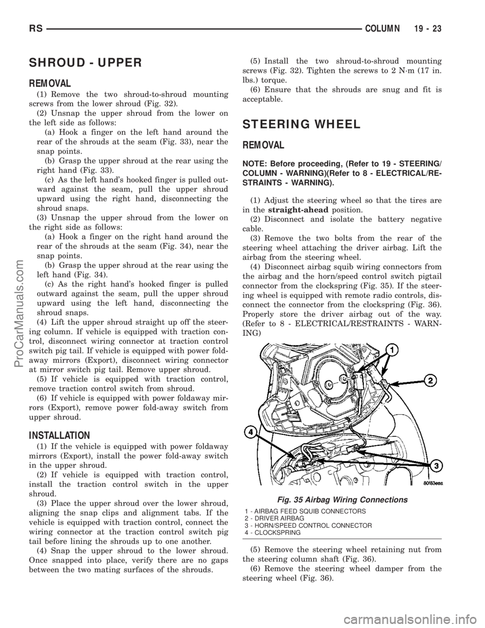
(4) Disconnect airbag squib wiring connectors from
the airbag and the horn/speed control switch pigtail
connector from the clockspring (Fig. 35). If the steer-
ing wheel is equipped with remote radio controls, dis-
connect the connector from the clockspring (Fig. 36).
Properly store the driver airbag out of the way.
(Refer to 8 - ELECTRICAL/RESTRAINTS - WARN-
ING)
(5) Remove the steering wheel retaining nut from
the steering column shaft (Fig. 36).
(6) Remove the steering wheel damper from the
steering wheel (Fig. 36).
Fig. 35 Airbag Wiring Connections
1 - AIRBAG FEED SQUIB CONNECTORS
2 - DRIVER AIRBAG
3 - HORN/SPEED CONTROL CONNECTOR
4 - CLOCKSPRING
RSCOLUMN19-23
ProCarManuals.com
Page 2006 of 2177
(ATC) heater-A/C control Delay and Recirculation
graphics will begin to flash when the calibration pro-
cedure has begun.
(3) The calibration procedure should take less than
two minutes to complete for the manual heater-A/C
control, and less than twenty seconds for the ATC
heater-A/C control. When the LEDs or graphics stop
flashing, the calibration procedure is complete.
(4) If the LEDs or graphics continue to flash
beyond the normal three minute (manual) or twenty
second (ATC) calibration time, it indicates that the
heater-A/C control has detected a failure and a Diag-
nostic Trouble Code (DTC) has been set. Use a
DRBIIItscan tool to perform further diagnosis. Refer
to the appropriate diagnostic information. The LEDs
or graphics will continue to flash even after the igni-
tion switch is cycled Off and On, until a successful
calibration is completed or until the vehicle has been
driven about 13 kilometers (8 miles).
REMOVAL
WARNING: ON VEHICLES EQUIPPED WITH AIR-
BAGS, DISABLE THE AIRBAG SYSTEM BEFORE
ATTEMPTING ANY STEERING WHEEL, STEERING
COLUMN, OR INSTRUMENT PANEL COMPONENT
DIAGNOSIS OR SERVICE. DISCONNECT AND ISO-
LATE THE BATTERY NEGATIVE (GROUND) CABLE,
THEN WAIT TWO MINUTES FOR THE AIRBAG SYS-
TEM CAPACITOR TO DISCHARGE BEFORE PER-
FORMING FURTHER DIAGNOSIS OR SERVICE. THIS
IS THE ONLY SURE WAY TO DISABLE THE AIRBAG
SYSTEM. FAILURE TO TAKE THE PROPER PRE-
CAUTIONS COULD RESULT IN ACCIDENTAL AIR-
BAG DEPLOYMENT AND POSSIBLE PERSONAL
INJURY.
(1) Disconnect and isolate the battery negative
cable.
(2) Remove the center bezel from the instrument
panel. (Refer to 23 - BODY/INSTRUMENT PANEL/
INSTRUMENT PANEL CENTER BEZEL - REMOV-
AL).
(3) Place the instrument panel center bezel unit
face down on a suitable work surface. Take the
proper precautions to protect the center bezel from
cosmetic damage.
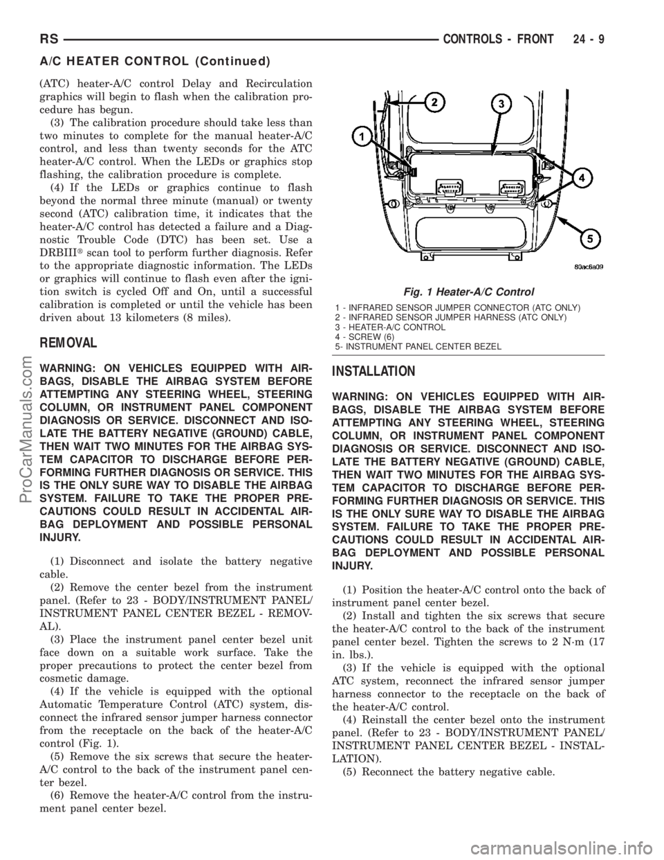
(4) If the vehicle is equipped with the optional
Automatic Temperature Control (ATC) system, dis-
connect the infrared sensor jumper harness connector
from the receptacle on the back of the heater-A/C
control (Fig. 1).
(5) Remove the six screws that secure the heater-
A/C control to the back of the instrument panel cen-
ter bezel.
(6) Remove the heater-A/C control from the instru-
ment panel center bezel.INSTALLATION
WARNING: ON VEHICLES EQUIPPED WITH AIR-
BAGS, DISABLE THE AIRBAG SYSTEM BEFORE
ATTEMPTING ANY STEERING WHEEL, STEERING
COLUMN, OR INSTRUMENT PANEL COMPONENT
DIAGNOSIS OR SERVICE. DISCONNECT AND ISO-
LATE THE BATTERY NEGATIVE (GROUND) CABLE,
THEN WAIT TWO MINUTES FOR THE AIRBAG SYS-
TEM CAPACITOR TO DISCHARGE BEFORE PER-
FORMING FURTHER DIAGNOSIS OR SERVICE. THIS
IS THE ONLY SURE WAY TO DISABLE THE AIRBAG
SYSTEM. FAILURE TO TAKE THE PROPER PRE-
CAUTIONS COULD RESULT IN ACCIDENTAL AIR-
BAG DEPLOYMENT AND POSSIBLE PERSONAL
INJURY.
(1) Position the heater-A/C control onto the back of
instrument panel center bezel.
(2) Install and tighten the six screws that secure
the heater-A/C control to the back of the instrument
panel center bezel. Tighten the screws to 2 N´m (17
in. lbs.).
(3) If the vehicle is equipped with the optional
ATC system, reconnect the infrared sensor jumper
harness connector to the receptacle on the back of
the heater-A/C control.
(4) Reinstall the center bezel onto the instrument
panel. (Refer to 23 - BODY/INSTRUMENT PANEL/
INSTRUMENT PANEL CENTER BEZEL - INSTAL-
LATION).
(5) Reconnect the battery negative cable.
Fig. 1 Heater-A/C Control
1 - INFRARED SENSOR JUMPER CONNECTOR (ATC ONLY)
2 - INFRARED SENSOR JUMPER HARNESS (ATC ONLY)
3 - HEATER-A/C CONTROL
4 - SCREW (6)
5- INSTRUMENT PANEL CENTER BEZEL
RSCONTROLS - FRONT24-9
A/C HEATER CONTROL (Continued)
ProCarManuals.com
Page 2040 of 2177
BLOWER MOTOR
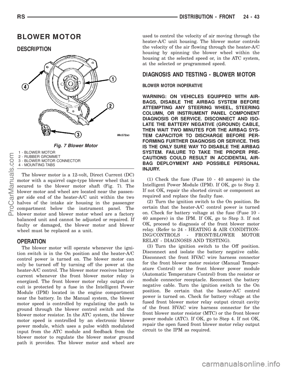
DESCRIPTION
The blower motor is a 12-volt, Direct Current (DC)
motor with a squirrel cage-type blower wheel that is
secured to the blower motor shaft (Fig. 7). The
blower motor and wheel are located near the passen-
ger side end of the heater-A/C unit within the two
halves of the intake air housing in the passenger
compartment below the instrument panel. The
blower motor and blower motor wheel are a factory
balanced unit and cannot be adjusted or repaired. If
faulty or damaged, the blower motor and blower
wheel must be replaced as a unit.
OPERATION
The blower motor will operate whenever the igni-
tion switch is in the On position and the heater-A/C
control power is turned on. The blower motor can
only be turned off by turning off the power at the
heater-A/C control. The blower motor receives battery
current whenever the front blower motor relay is
energized. The front blower motor relay output cir-
cuit is protected by a fuse in the Intelligent Power
Module (IPM) located in the engine compartment
near the battery. In the Manual system, the blower
motor speed is controlled by regulating the path to
ground through the blower control switch and the
blower motor resistor. In the ATC system, the blower
motor speed is controlled by an electronic blower
power module, which uses a pulse width modulated
input from the ATC module and feedback from the
blower motor to regulate the blower motor ground
path it provides. The blower motor and wheel areused to control the velocity of air moving through the
heater-A/C unit housing. The blower motor controls
the velocity of the air flowing through the heater-A/C
housing by spinning the blower wheel within the
housing at the selected speed or, in the ATC system,
at the selected or programmed speed.
DIAGNOSIS AND TESTING - BLOWER MOTOR
BLOWER MOTOR INOPERATIVE
WARNING: ON VEHICLES EQUIPPED WITH AIR-
BAGS, DISABLE THE AIRBAG SYSTEM BEFORE
ATTEMPTING ANY STEERING WHEEL, STEERING
COLUMN, OR INSTRUMENT PANEL COMPONENT
DIAGNOSIS OR SERVICE. DISCONNECT AND ISO-
LATE THE BATTERY NEGATIVE (GROUND) CABLE,
THEN WAIT TWO MINUTES FOR THE AIRBAG SYS-
TEM CAPACITOR TO DISCHARGE BEFORE PER-
FORMING FURTHER DIAGNOSIS OR SERVICE. THIS
IS THE ONLY SURE WAY TO DISABLE THE AIRBAG
SYSTEM. FAILURE TO TAKE THE PROPER PRE-
CAUTIONS COULD RESULT IN ACCIDENTAL AIR-
BAG DEPLOYMENT AND POSSIBLE PERSONAL
INJURY.
(1) Check the fuse (Fuse 10 - 40 ampere) in the
Intelligent Power Module (IPM). If OK, go to Step 2.
If not OK, repair the shorted circuit or component as
required and replace the faulty fuse.
(2) Turn the ignition switch to the On position. Be
certain that the heater-A/C control power is turned
on. Check for battery voltage at the fuse (Fuse 10 -
40 ampere) in the IPM. If OK, go to Step 3. If not
OK, proceed to diagnosis of the front blower motor
relay. (Refer to 24 - HEATING & AIR CONDITION-
ING/CONTROLS - FRONT/BLOWER MOTOR
RELAY - DIAGNOSIS AND TESTING).
(3) Turn the ignition switch to the Off position.
Disconnect and isolate the battery negative cable.
Disconnect the front HVAC wire harness connector
for the front blower motor resistor (Manual Temper-
ature Control) or the front blower power module
(Automatic Temperature Control) from the resistor or
module connector receptacle. Reconnect the battery
negative cable. Turn the ignition switch to the On
position. Be certain that the heater-A/C control
power is turned on. Check for battery voltage at the
fused front blower motor relay output circuit cavity
of the front HVAC wire harness connector for the
front blower motor resistor (MTC) or the front blower
power module (ATC). If OK, go to Step 4. If not OK,
repair the open fused front blower motor relay output
circuit to the IPM as required.
Fig. 7 Blower Motor
1 - BLOWER MOTOR
2 - RUBBER GROMMET
3 - BLOWER MOTOR CONNECTOR
4 - MOUNTING TABS
RSDISTRIBUTION - FRONT24-43
ProCarManuals.com