2003 CHRYSLER CARAVAN belt
[x] Cancel search: beltPage 1725 of 2177
RCONSTRUCTION
TYPER - RADIAL
B - BIAS BELTED
D - DIAGONAL (BIAS)
16WHEEL DIAMETER SHOWN IN INCHES
97LOAD INDEX *
TSPEED RATING *
* NOTE: Consult the tire manufacturer regarding
any questions on tire specifications or capabilities.
TIRE CHAINS
Refer to the owners manual supplied with the vehi-
cle to determine whether the use of tire chains is per-
mitted on this vehicle.
DESCRIPTION - RADIAL-PLY TIRES
Radial-ply tires improve handling, tread life, ride
quality and decrease rolling resistance.
Radial-ply tires must always be used in sets of four
and under no circumstances should they be used on
the front only. It is recommended that tires from dif-
ferent manufacturers NOT be mixed. They may be
mixed with a temporary spare tire when necessary. A
maximum speed of 80 km/h (50 mph) is recom-
mended while a temporary spare is in use.
Radial-ply tires have the same load-carrying capac-
ity as other types of tires of the same size. They also
use the same recommended inflation pressures.
DESCRIPTION - REPLACEMENT TIRES
WARNING: FAILURE TO EQUIP THE VEHICLE WITH
TIRES HAVING ADEQUATE SPEED CAPABILITY
CAN RESULT IN SUDDEN TIRE FAILURE.It is recommended that tires equivalent to the orig-
inal equipment tires be used when replacement is
needed.
Failure to use equivalent replacement tires may
adversely affect the safety and handling of the vehi-
cle.
The original equipment tires provide a proper com-
bination of many characteristics such as:
²Ride
²Noise
²Handling
²Durability
²Tread life
²Traction
²Rolling resistance
²Speed capability
The use of tires smaller than the minimum tire
size approved for the vehicle can result in tire over-
loading and failure.
Use tires that have the approved load rating for
the vehicle and never overload them. Failure to equip
the vehicle with tires having adequate speed capabil-
ity can result in sudden tire failure and loss of vehi-
cle control.
The use of oversize tires may cause interference
with vehicle components. Under extremes of suspen-
sion and steering travel, interference with vehicle
components may cause tire damage.
DESCRIPTION - SPARE TIRE (TEMPORARY)
The temporary (convenience) spare tire is designed
for emergency use only. The original tire should be
repaired and reinstalled, or replaced with a new, at
the first opportunity.
The temporary (convenience) spare tire should be
inflated to the pressure listed on its sidewall. Do not
exceed speeds of 80 km/h (50 mph) when the tempo-
rary spare tire is in use on the vehicle. Refer to the
Owner's Manual for more details.
DIAGNOSIS AND TESTING
DIAGNOSIS AND TESTING - TIRE NOISE
Unusual tire noise can be associated with tire and
wheel vibration or irregular tire wear. For vibration,
(Refer to 22 - TIRES/WHEELS - DIAGNOSIS AND
TESTING). For irregular tire wear, (Refer to 22 -
TIRES/WHEELS/TIRES - DIAGNOSIS AND TEST-
ING).
DIAGNOSIS AND TESTING - TIRE/VEHICLE
LEAD
Use the following Vehicle Lead Diagnosis And Cor-
rection Chart to diagnose and correct a vehicle lead
or drift problem.
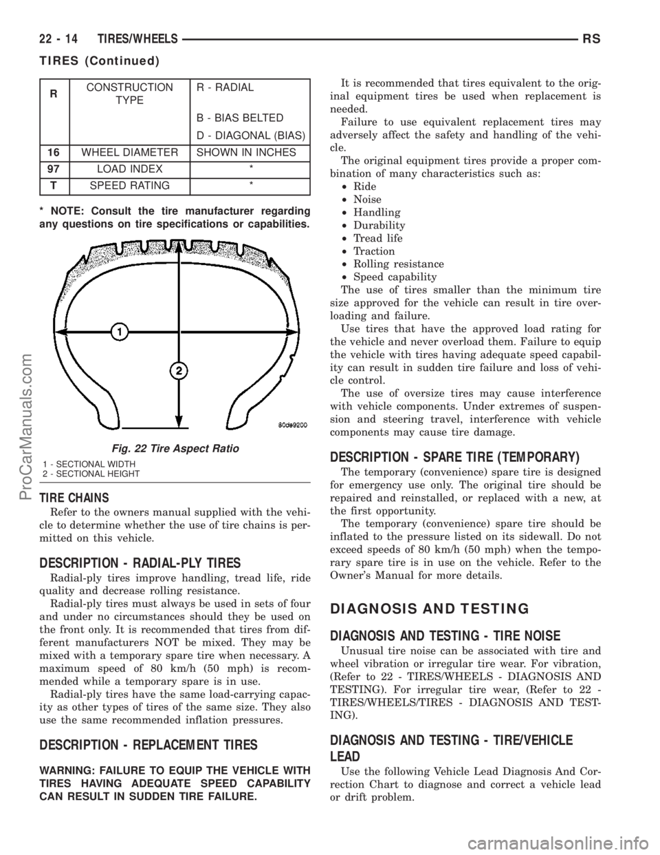
Fig. 22 Tire Aspect Ratio
1 - SECTIONAL WIDTH
2 - SECTIONAL HEIGHT
22 - 14 TIRES/WHEELSRS
TIRES (Continued)
ProCarManuals.com
Page 1744 of 2177
SPECIFICATIONS
TORQUE
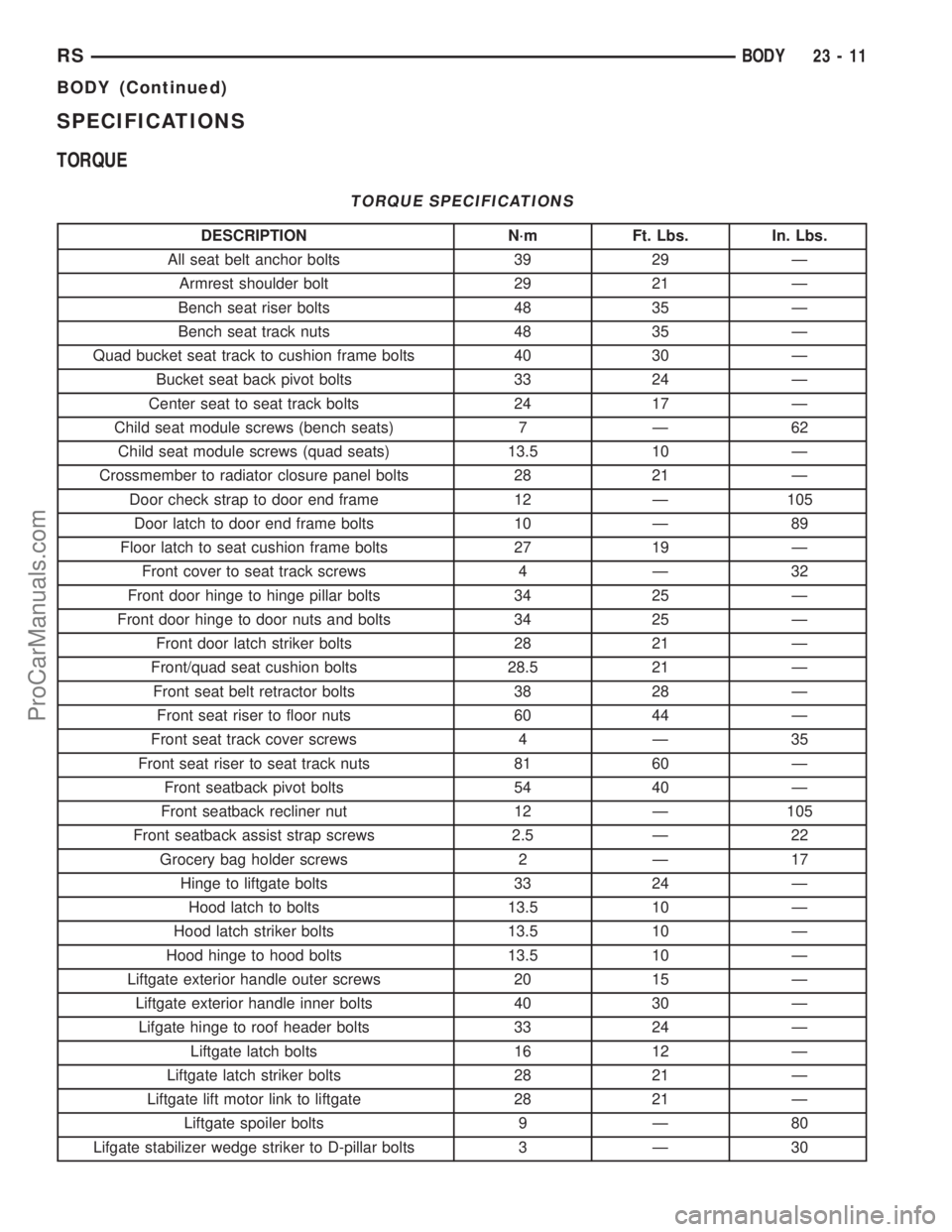
TORQUE SPECIFICATIONS
DESCRIPTION N´m Ft. Lbs. In. Lbs.
All seat belt anchor bolts 39 29 Ð
Armrest shoulder bolt 29 21 Ð
Bench seat riser bolts 48 35 Ð
Bench seat track nuts 48 35 Ð
Quad bucket seat track to cushion frame bolts 40 30 Ð
Bucket seat back pivot bolts 33 24 Ð
Center seat to seat track bolts 24 17 Ð
Child seat module screws (bench seats) 7 Ð 62
Child seat module screws (quad seats) 13.5 10 Ð
Crossmember to radiator closure panel bolts 28 21 Ð
Door check strap to door end frame 12 Ð 105
Door latch to door end frame bolts 10 Ð 89
Floor latch to seat cushion frame bolts 27 19 Ð
Front cover to seat track screws 4 Ð 32
Front door hinge to hinge pillar bolts 34 25 Ð
Front door hinge to door nuts and bolts 34 25 Ð
Front door latch striker bolts 28 21 Ð
Front/quad seat cushion bolts 28.5 21 Ð
Front seat belt retractor bolts 38 28 Ð
Front seat riser to floor nuts 60 44 Ð
Front seat track cover screws 4 Ð 35
Front seat riser to seat track nuts 81 60 Ð
Front seatback pivot bolts 54 40 Ð
Front seatback recliner nut 12 Ð 105
Front seatback assist strap screws 2.5 Ð 22
Grocery bag holder screws 2 Ð 17
Hinge to liftgate bolts 33 24 Ð
Hood latch to bolts 13.5 10 Ð
Hood latch striker bolts 13.5 10 Ð
Hood hinge to hood bolts 13.5 10 Ð
Liftgate exterior handle outer screws 20 15 Ð
Liftgate exterior handle inner bolts 40 30 Ð
Lifgate hinge to roof header bolts 33 24 Ð
Liftgate latch bolts 16 12 Ð
Liftgate latch striker bolts 28 21 Ð
Liftgate lift motor link to liftgate 28 21 Ð
Liftgate spoiler bolts 9 Ð 80
Lifgate stabilizer wedge striker to D-pillar bolts 3 Ð 30
RSBODY23-11
BODY (Continued)
ProCarManuals.com
Page 1745 of 2177
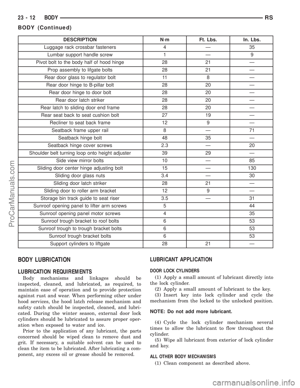
DESCRIPTION N´m Ft. Lbs. In. Lbs.
Luggage rack crossbar fasteners 4 Ð 35
Lumbar support handle screw 1 Ð 9
Pivot bolt to the body half of hood hinge 28 21 Ð
Prop assembly to lifgate bolts 28 21 Ð
Rear door glass to regulator bolt 11 8 Ð
Rear door hinge to B-pillar bolt 28 20 Ð
Rear door hinge to door bolt 28 20 Ð
Rear door latch striker 28 20 Ð
Rear latch to sliding door end frame 28 20 Ð
Rear seat back to seat cushion bolt 27 19 Ð
Recliner to seat back frame 12 9 Ð
Seatback frame upper rail 8 Ð 71
Seatback hinge bolt 48 35 Ð
Seatback hinge cover screws 2.3 Ð 20
Shoulder belt turning loop onto height adjuster 39 29 Ð
Side view mirror bolts 10 Ð 85
Sliding door center hinge adjusting bolt 15 Ð 130
Sliding door glass nuts 3.4 Ð 30
Sliding door latch striker 28 21 Ð
Sliding door to roller arm bracket 12 9 Ð
Storage bin track guide to seat riser 3.5 Ð 31
Sunroof opening panel to lifter arm screws 5 44
Sunroof opening panel motor screws 4 35
Sunroof trough bracket to roof bolts 6 53
Sunroof trough to trough bracket bolts 6 53
Sunroof trough bracket bolts 6 53
Support cylinders to liftgate 28 21 Ð
BODY LUBRICATION
LUBRICATION REQUIREMENTS
Body mechanisms and linkages should be
inspected, cleaned, and lubricated, as required, to
maintain ease of operation and to provide protection
against rust and wear. When performing other under
hood services, the hood latch release mechanism and
safety catch should be inspected, cleaned, and lubri-
cated. During the winter season, external door lock
cylinders should be lubricated to assure proper oper-
ation when exposed to water and ice.
Prior to the application of any lubricant, the parts
concerned should be wiped clean to remove dust and
grit. If necessary, a suitable solvent can be used to
clean the item to be lubricated. After lubricating a com-
ponent, any excess oil or grease should be removed.
LUBRICANT APPLICATION
DOOR LOCK CYLINDERS
(1) Apply a small amount of lubricant directly into
the lock cylinder.
(2) Apply a small amount of lubricant to the key.
(3) Insert key into lock cylinder and cycle the
mechanism from the locked to the unlocked position.
NOTE: Do not add more lubricant.
(4) Cycle the lock cylinder mechanism several
times to allow the lubricant to flow throughout the
cylinder.
(5) Wipe all lubricant from exterior of lock cylinder
and key.
ALL OTHER BODY MECHANISMS
(1) Clean component as described above.
23 - 12 BODYRS
BODY (Continued)
ProCarManuals.com
Page 1747 of 2177
DOOR - FRONT
TABLE OF CONTENTS
page page
APPLIQUE
REMOVAL.............................14
INSTALLATION.........................14
CHECK STRAP
REMOVAL.............................15
INSTALLATION.........................15
DOOR
REMOVAL.............................15
INSTALLATION.........................16
DOOR GLASS
REMOVAL.............................17
INSTALLATION.........................17
FRAME CLOSEOUT MOLDING
REMOVAL ± A-PILLAR-HEADER, OR B-PILLAR . 17
INSTALLATION ± A-PILLAR-HEADER, OR
B-PILLAR............................17
HINGE
REMOVAL.............................18
INSTALLATION.........................18
LATCH
REMOVAL.............................18
INSTALLATION.........................19
LATCH STRIKER
REMOVAL.............................19INSTALLATION.........................19
LOCK CYLINDER
REMOVAL.............................19
INSTALLATION.........................20
TRIM PANEL
REMOVAL.............................20
INSTALLATION.........................20
WATERSHIELD
REMOVAL.............................21
INSTALLATION.........................21
WINDOW CRANK
REMOVAL.............................21
INSTALLATION.........................21
EXTERIOR HANDLE
REMOVAL.............................22
INSTALLATION.........................22
WINDOW REGULATOR - POWER
REMOVAL.............................22
INSTALLATION.........................22
WINDOW REGULATOR - MANUAL
REMOVAL.............................23
INSTALLATION.........................23
APPLIQUE
REMOVAL
(1) Roll door glass down.
(2) Remove outer door belt molding.
(3) Disengage clips holding front edge of applique
to door frame.
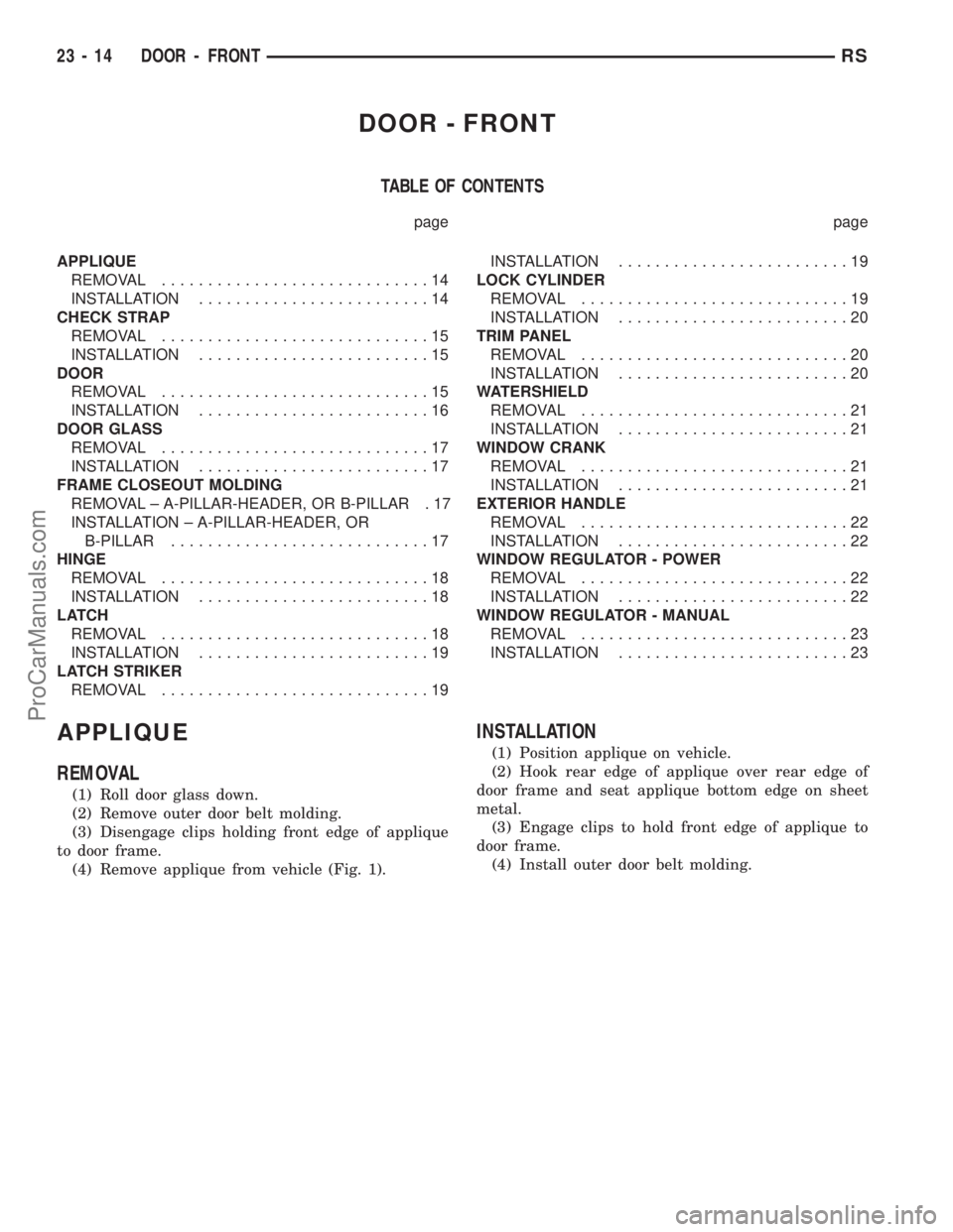
(4) Remove applique from vehicle (Fig. 1).
INSTALLATION
(1) Position applique on vehicle.
(2) Hook rear edge of applique over rear edge of
door frame and seat applique bottom edge on sheet
metal.
(3) Engage clips to hold front edge of applique to
door frame.
(4) Install outer door belt molding.
23 - 14 DOOR - FRONTRS
ProCarManuals.com
Page 1750 of 2177
DOOR GLASS
REMOVAL
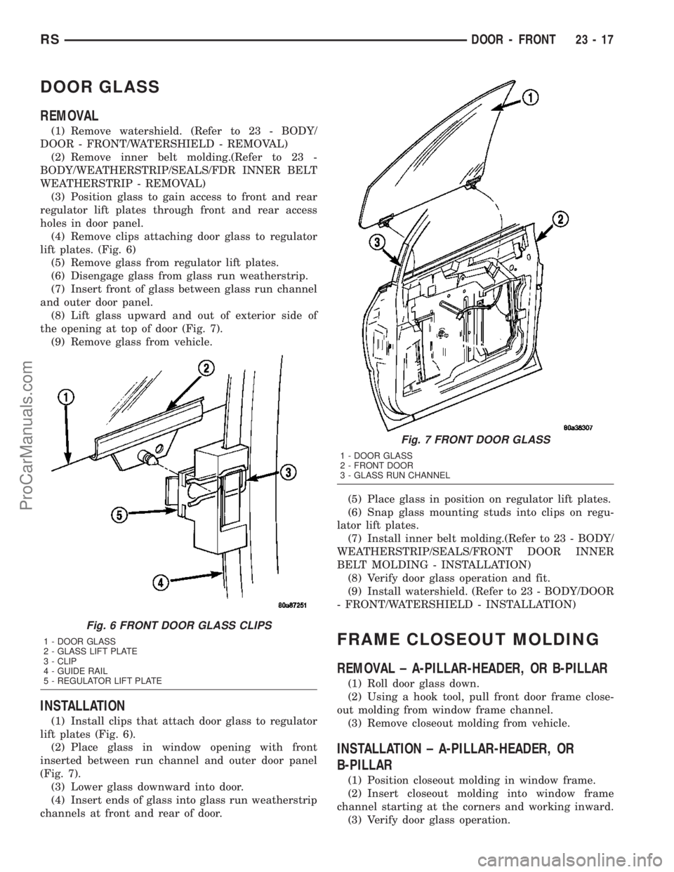
(1) Remove watershield. (Refer to 23 - BODY/
DOOR - FRONT/WATERSHIELD - REMOVAL)
(2) Remove inner belt molding.(Refer to 23 -
BODY/WEATHERSTRIP/SEALS/FDR INNER BELT
WEATHERSTRIP - REMOVAL)
(3) Position glass to gain access to front and rear
regulator lift plates through front and rear access
holes in door panel.
(4) Remove clips attaching door glass to regulator
lift plates. (Fig. 6)
(5) Remove glass from regulator lift plates.
(6) Disengage glass from glass run weatherstrip.
(7) Insert front of glass between glass run channel
and outer door panel.
(8) Lift glass upward and out of exterior side of
the opening at top of door (Fig. 7).
(9) Remove glass from vehicle.
INSTALLATION
(1) Install clips that attach door glass to regulator
lift plates (Fig. 6).
(2) Place glass in window opening with front
inserted between run channel and outer door panel
(Fig. 7).
(3) Lower glass downward into door.
(4) Insert ends of glass into glass run weatherstrip
channels at front and rear of door.(5) Place glass in position on regulator lift plates.
(6) Snap glass mounting studs into clips on regu-
lator lift plates.
(7) Install inner belt molding.(Refer to 23 - BODY/
WEATHERSTRIP/SEALS/FRONT DOOR INNER
BELT MOLDING - INSTALLATION)
(8) Verify door glass operation and fit.
(9) Install watershield. (Refer to 23 - BODY/DOOR
- FRONT/WATERSHIELD - INSTALLATION)
FRAME CLOSEOUT MOLDING
REMOVAL ± A-PILLAR-HEADER, OR B-PILLAR
(1) Roll door glass down.
(2) Using a hook tool, pull front door frame close-
out molding from window frame channel.
(3) Remove closeout molding from vehicle.
INSTALLATION ± A-PILLAR-HEADER, OR
B-PILLAR
(1) Position closeout molding in window frame.
(2) Insert closeout molding into window frame
channel starting at the corners and working inward.
(3) Verify door glass operation.
Fig. 6 FRONT DOOR GLASS CLIPS
1 - DOOR GLASS
2 - GLASS LIFT PLATE
3 - CLIP
4 - GUIDE RAIL
5 - REGULATOR LIFT PLATE
Fig. 7 FRONT DOOR GLASS
1 - DOOR GLASS
2 - FRONT DOOR
3 - GLASS RUN CHANNEL
RSDOOR - FRONT23-17
ProCarManuals.com
Page 1753 of 2177
INSTALLATION
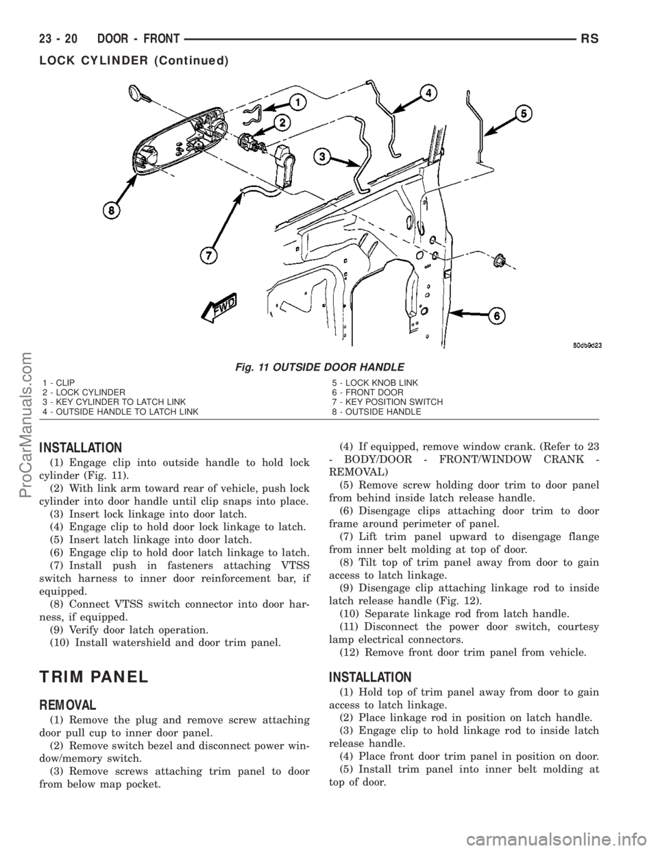
(1) Engage clip into outside handle to hold lock
cylinder (Fig. 11).
(2) With link arm toward rear of vehicle, push lock
cylinder into door handle until clip snaps into place.
(3) Insert lock linkage into door latch.
(4) Engage clip to hold door lock linkage to latch.
(5) Insert latch linkage into door latch.
(6) Engage clip to hold door latch linkage to latch.
(7) Install push in fasteners attaching VTSS
switch harness to inner door reinforcement bar, if
equipped.
(8) Connect VTSS switch connector into door har-
ness, if equipped.
(9) Verify door latch operation.
(10) Install watershield and door trim panel.
TRIM PANEL
REMOVAL
(1) Remove the plug and remove screw attaching
door pull cup to inner door panel.
(2) Remove switch bezel and disconnect power win-
dow/memory switch.
(3) Remove screws attaching trim panel to door
from below map pocket.(4) If equipped, remove window crank. (Refer to 23
- BODY/DOOR - FRONT/WINDOW CRANK -
REMOVAL)
(5) Remove screw holding door trim to door panel
from behind inside latch release handle.
(6) Disengage clips attaching door trim to door
frame around perimeter of panel.
(7) Lift trim panel upward to disengage flange
from inner belt molding at top of door.
(8) Tilt top of trim panel away from door to gain
access to latch linkage.
(9) Disengage clip attaching linkage rod to inside
latch release handle (Fig. 12).
(10) Separate linkage rod from latch handle.
(11) Disconnect the power door switch, courtesy
lamp electrical connectors.
(12) Remove front door trim panel from vehicle.
INSTALLATION
(1) Hold top of trim panel away from door to gain
access to latch linkage.
(2) Place linkage rod in position on latch handle.
(3) Engage clip to hold linkage rod to inside latch
release handle.
(4) Place front door trim panel in position on door.
(5) Install trim panel into inner belt molding at
top of door.
Fig. 11 OUTSIDE DOOR HANDLE
1 - CLIP
2 - LOCK CYLINDER
3 - KEY CYLINDER TO LATCH LINK
4 - OUTSIDE HANDLE TO LATCH LINK5 - LOCK KNOB LINK
6 - FRONT DOOR
7 - KEY POSITION SWITCH
8 - OUTSIDE HANDLE
23 - 20 DOOR - FRONTRS
LOCK CYLINDER (Continued)
ProCarManuals.com
Page 1755 of 2177
EXTERIOR HANDLE
REMOVAL
(1) Roll door glass up.
(2) Remove the watershield as necessary to gain
access to the outside door handle. (Refer to 23 -
BODY/DOOR - FRONT/WATERSHIELD -
REMOVAL)
(3) Through access hole at rear of inner door
panel, disconnect Vehicle Theft Security System
(VTSS) switch connector from door harness, if
equipped.
(4) Disengage push in fasteners attaching VTSS
switch harness to inner door reinforcement bar, if
equipped.
(5) Disengage clip holding door latch linkage to
door latch (Fig. 11).
(6) Remove latch linkage from latch.
(7) Disengage clip holding door lock linkage to
door latch.
(8) Remove lock linkage from latch.
(9) Remove nuts holding outside door handle to
door outer panel.
(10) Remove outside door handle from vehicle.
INSTALLATION
If outside door handle replacement is necessary,
transfer lock cylinder from the original handle to the
new one.
(1) Place outside door handle in position on vehi-
cle.
(2) Install nuts attaching outside door handle to
door outer panel (Fig. 11). Tighten nuts to 6 N´m (50
in. lbs.).
(3) Insert lock linkage into door latch.
(4) Engage clip to hold door lock linkage to latch.
(5) Insert latch linkage into door latch.
(6) Engage clip to hold door latch linkage to latch.
(7) Install push-in fasteners to hold VTSS switch
harness to inner door reinforcement bar, if equipped.
(8) Connect VTSS switch connector into door har-
ness, if equipped.
(9) Verify door latch operation.
(10) Install sound shield and door trim panel.
WINDOW REGULATOR -
POWER
REMOVAL
(1) Remove watershield. (Refer to 23 - BODY/
DOOR - FRONT/WATERSHIELD - REMOVAL)
(2) Remove inner belt molding.(Refer to 23 -
BODY/WEATHERSTRIP/SEALS/FDR INNER BELT
WEATHERSTRIP - REMOVAL)(3) Remove door glass. (Refer to 23 - BODY/DOOR
- FRONT/DOOR GLASS - REMOVAL).
(4) Disconnect wire connector from power window
motor.
(5) Loosen screws attaching front and rear window
guide rails to inner door panel.
(6) Remove screw heads on guide rails from key
hole slots in inner door panel.
(7) Loosen screws attaching motor/housing to inner
door panel.
(8) Remove regulator from inner door panel.
(9) Extract rear guide rail through inner door
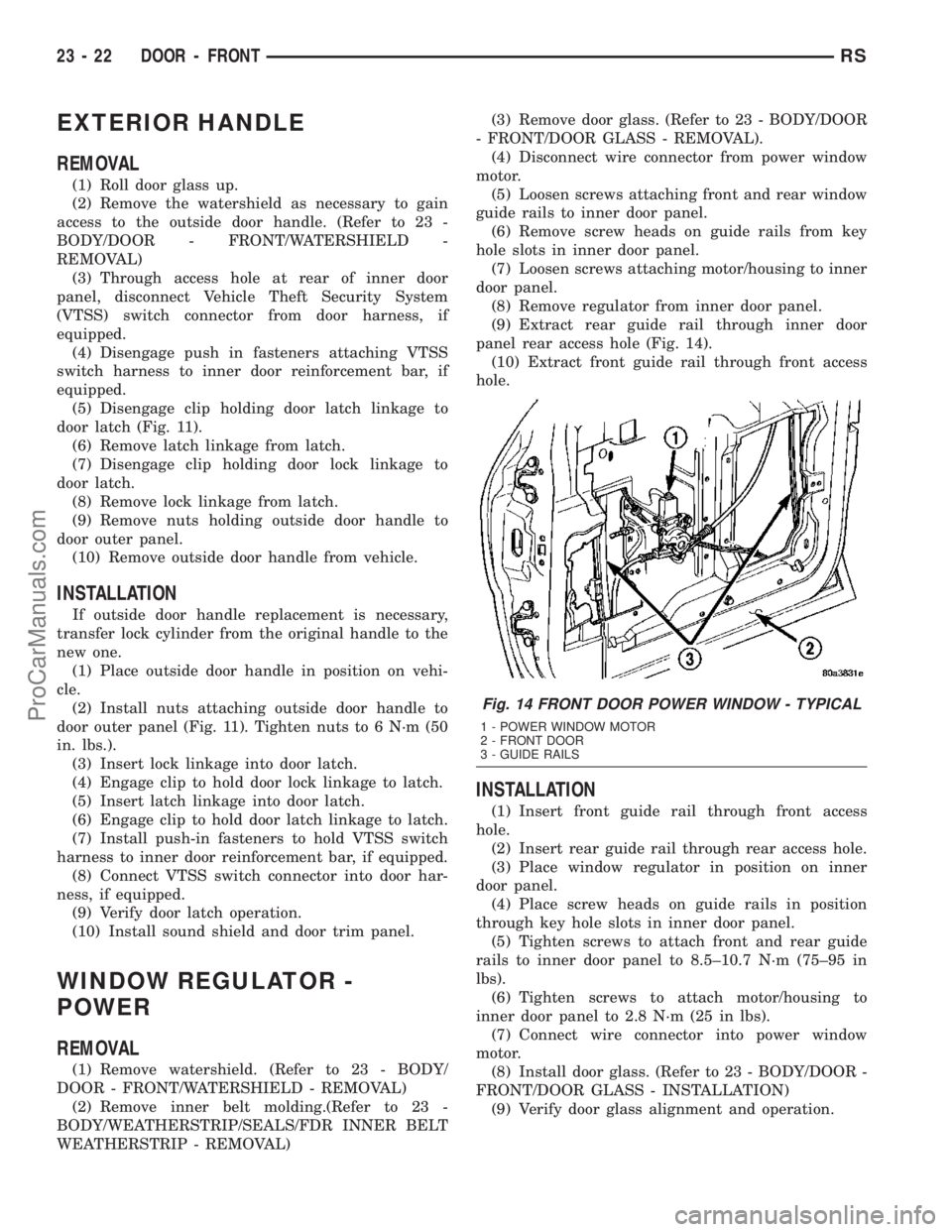
panel rear access hole (Fig. 14).
(10) Extract front guide rail through front access
hole.
INSTALLATION
(1) Insert front guide rail through front access
hole.
(2) Insert rear guide rail through rear access hole.
(3) Place window regulator in position on inner
door panel.
(4) Place screw heads on guide rails in position
through key hole slots in inner door panel.
(5) Tighten screws to attach front and rear guide
rails to inner door panel to 8.5±10.7 N´m (75±95 in
lbs).
(6) Tighten screws to attach motor/housing to
inner door panel to 2.8 N´m (25 in lbs).
(7) Connect wire connector into power window
motor.
(8) Install door glass. (Refer to 23 - BODY/DOOR -
FRONT/DOOR GLASS - INSTALLATION)
(9) Verify door glass alignment and operation.
Fig. 14 FRONT DOOR POWER WINDOW - TYPICAL
1 - POWER WINDOW MOTOR
2 - FRONT DOOR
3 - GUIDE RAILS
23 - 22 DOOR - FRONTRS
ProCarManuals.com
Page 1756 of 2177
(10) Install inner belt molding (Refer to 23 -
BODY/WEATHERSTRIP/SEALS/FDR INNER BELT
WEATHERSTRIP - INSTALLATION)
(11) Install watershield. (Refer to 23 - BODY/
DOOR - FRONT/WATERSHIELD - INSTALLATION)
WINDOW REGULATOR -
MANUAL
REMOVAL
(1) Remove watershield. (Refer to 23 - BODY/
DOOR - FRONT/WATERSHIELD - REMOVAL)
(2) Remove inner belt molding.(Refer to 23 -
BODY/WEATHERSTRIP/SEALS/FDR INNER BELT
WEATHERSTRIP - REMOVAL)
(3) Remove door glass. (Refer to 23 - BODY/DOOR
- FRONT/DOOR GLASS - REMOVAL).
(4) Loosen screws attaching front and rear window
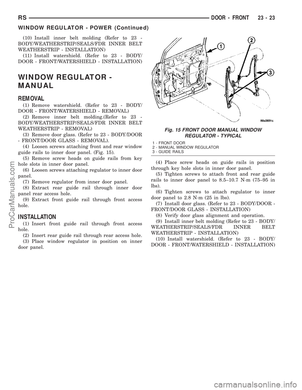
guide rails to inner door panel. (Fig. 15).
(5) Remove screw heads on guide rails from key
hole slots in inner door panel.
(6) Loosen screws attaching regulator to inner door
panel.
(7) Remove regulator from inner door panel.
(8) Extract rear guide rail through inner door
panel rear access hole.
(9) Extract front guide rail through front access
hole.
INSTALLATION
(1) Insert front guide rail through front access
hole.
(2) Insert rear guide rail through rear access hole.
(3) Place window regulator in position on inner
door panel.(4) Place screw heads on guide rails in position
through key hole slots in inner door panel.
(5) Tighten screws to attach front and rear guide
rails to inner door panel to 8.5±10.7 N´m (75±95 in
lbs).
(6) Tighten screws to attach regulator to inner
door panel to 2.8 N´m (25 in lbs).
(7) Install door glass. (Refer to 23 - BODY/DOOR -
FRONT/DOOR GLASS - INSTALLATION)
(8) Verify door glass alignment and operation.
(9) Install inner belt molding (Refer to 23 - BODY/
WEATHERSTRIP/SEALS/FDR INNER BELT
WEATHERSTRIP - INSTALLATION)
(10) Install watershield. (Refer to 23 - BODY/
DOOR - FRONT/WATERSHIELD - INSTALLATION)
Fig. 15 FRONT DOOR MANUAL WINDOW
REGULATOR - TYPICAL
1 - FRONT DOOR
2 - MANUAL WINDOW REGULATOR
3 - GUIDE RAILS
RSDOOR - FRONT23-23
WINDOW REGULATOR - POWER (Continued)
ProCarManuals.com