2003 CHRYSLER CARAVAN instrument panel
[x] Cancel search: instrument panelPage 1412 of 2177
LOCK CYLINDER HOUSING
DESCRIPTION - IGNITION INTERLOCK
All vehicles equipped with automatic transaxles
have an interlock system. The system prevents shift-
ing the vehicle out of Park unless the ignition lock
cylinder is in the Unlock, Run or Start position. In
addition, the operator cannot rotate the key to the
lock position unless the shifter is in the park posi-
tion. On vehicles equipped with floor shift refer to
the - Transaxle for Automatic Transmission Shifter/
Ignition Interlock.
REMOVAL
NOTE: Before proceeding, review all Steering Col-
umn and Airbag Warnings and Cautions. (Refer to
19 - STEERING/COLUMN - WARNING)(Refer to 8 -
ELECTRICAL/RESTRAINTS - WARNING)
(1) Remove battery ground cable terminal from
battery negative post and isolate.
(2) Under instrument panel, remove silencer panel
below lower steering column cover.
(3) Remove screws securing lower steering column
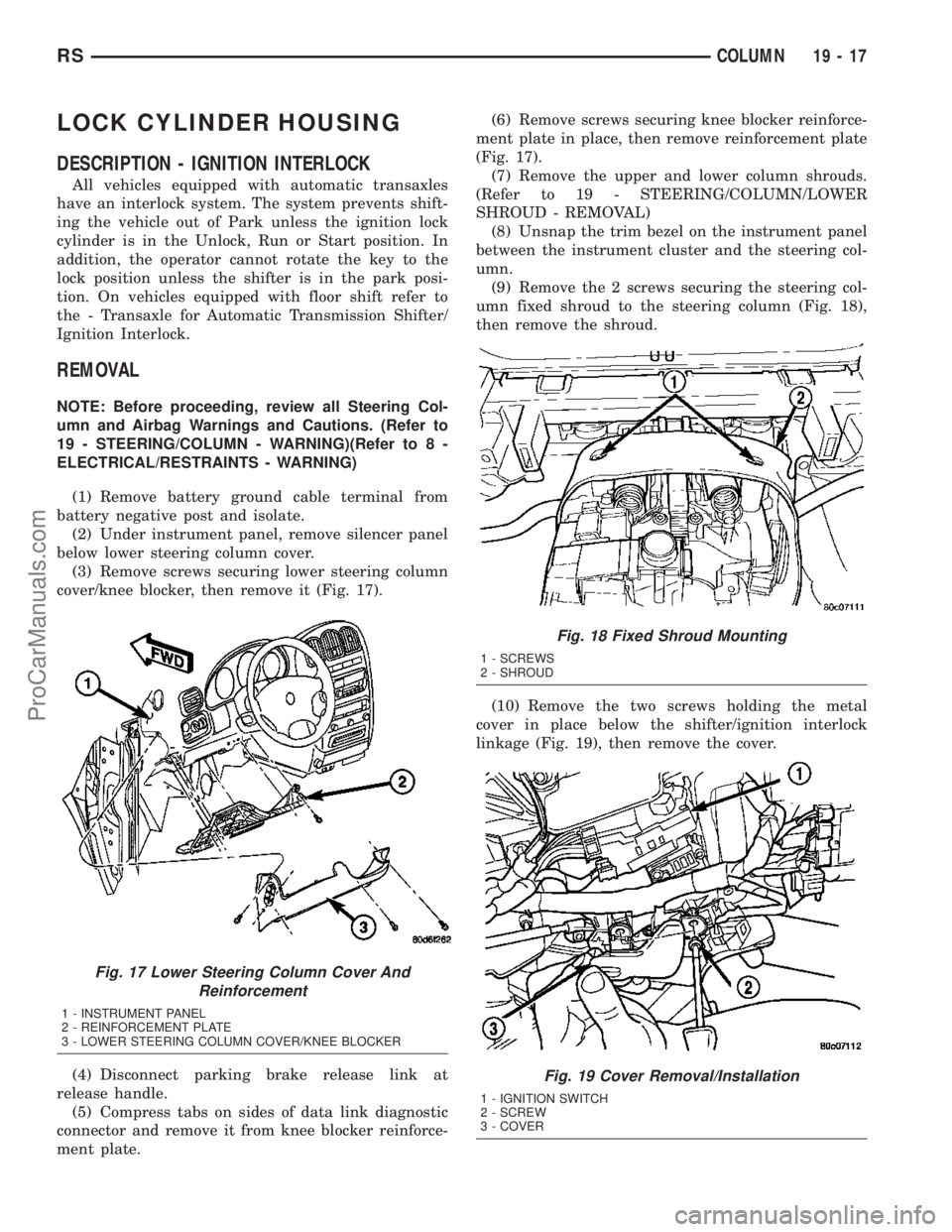
cover/knee blocker, then remove it (Fig. 17).
(4) Disconnect parking brake release link at
release handle.
(5) Compress tabs on sides of data link diagnostic
connector and remove it from knee blocker reinforce-
ment plate.(6) Remove screws securing knee blocker reinforce-
ment plate in place, then remove reinforcement plate
(Fig. 17).
(7) Remove the upper and lower column shrouds.
(Refer to 19 - STEERING/COLUMN/LOWER
SHROUD - REMOVAL)
(8) Unsnap the trim bezel on the instrument panel
between the instrument cluster and the steering col-
umn.
(9) Remove the 2 screws securing the steering col-
umn fixed shroud to the steering column (Fig. 18),
then remove the shroud.
(10) Remove the two screws holding the metal
cover in place below the shifter/ignition interlock
linkage (Fig. 19), then remove the cover.
Fig. 17 Lower Steering Column Cover And
Reinforcement
1 - INSTRUMENT PANEL
2 - REINFORCEMENT PLATE
3 - LOWER STEERING COLUMN COVER/KNEE BLOCKER
Fig. 18 Fixed Shroud Mounting
1 - SCREWS
2 - SHROUD
Fig. 19 Cover Removal/Installation
1 - IGNITION SWITCH
2 - SCREW
3 - COVER
RSCOLUMN19-17
ProCarManuals.com
Page 1415 of 2177
retaining tab on the lever with the ramp on the link
(Fig. 20), then pushing the two together.
(12) Install the metal cover in place below the
shifter/ignition interlock linkage using the two
screws (Fig. 19).
(13) Install the steering column fixed shroud on
the steering column (Fig. 18) using its 2 mounting
screws.
(14) Install the trim bezel on the instrument panel
above the steering column. The trim bezel is
mounted to the instrument panel using 2 screws (one
on each side of the column) and retaining clips.
(15) Install the lower and upper steering column
shrouds. (Refer to 19 - STEERING/COLUMN/
LOWER SHROUD - INSTALLATION)
(16) Install the knee blocker reinforcement plate
(Fig. 17).
(17) Connect the parking brake release link to the
release handle.
(18) Install the data link diagnostic connector to
the mounting hole in the reinforcement plate.
(19) Install the lower steering column cover/knee
blocker (Fig. 17).
(20) Connect the negative (ground) cable to the
battery terminal.
KEY/LOCK CYLINDER
DESCRIPTION
The lock cylinder is inserted in the end of the
housing opposite the ignition switch.
OPERATION
The ignition key rotates the cylinder to 5 different
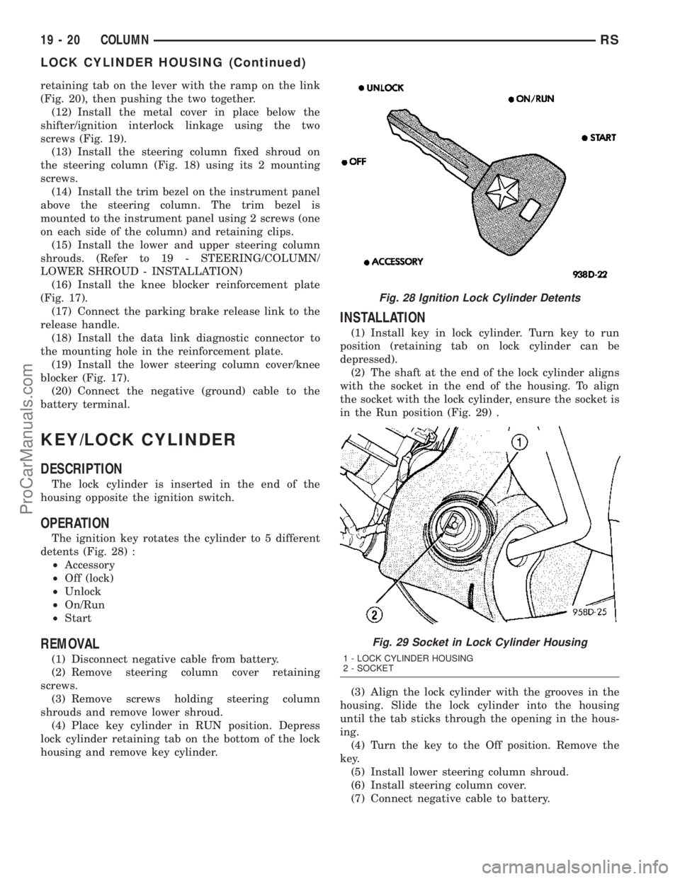
detents (Fig. 28) :
²Accessory
²Off (lock)
²Unlock
²On/Run
²Start
REMOVAL
(1) Disconnect negative cable from battery.
(2) Remove steering column cover retaining
screws.
(3) Remove screws holding steering column
shrouds and remove lower shroud.
(4) Place key cylinder in RUN position. Depress
lock cylinder retaining tab on the bottom of the lock
housing and remove key cylinder.
INSTALLATION
(1) Install key in lock cylinder. Turn key to run
position (retaining tab on lock cylinder can be
depressed).
(2) The shaft at the end of the lock cylinder aligns
with the socket in the end of the housing. To align
the socket with the lock cylinder, ensure the socket is
in the Run position (Fig. 29) .
(3) Align the lock cylinder with the grooves in the
housing. Slide the lock cylinder into the housing
until the tab sticks through the opening in the hous-
ing.
(4) Turn the key to the Off position. Remove the
key.
(5) Install lower steering column shroud.
(6) Install steering column cover.
(7) Connect negative cable to battery.
Fig. 28 Ignition Lock Cylinder Detents
Fig. 29 Socket in Lock Cylinder Housing
1 - LOCK CYLINDER HOUSING
2 - SOCKET
19 - 20 COLUMNRS
LOCK CYLINDER HOUSING (Continued)
ProCarManuals.com
Page 1416 of 2177
GEAR SHIFT LEVER
REMOVAL
(1) Remove the knee blocker (Refer to 23 - BODY/
INSTRUMENT PANEL/STEERING COLUMN
OPENING COVER - REMOVAL).
(2) Remove the knee blocker reinforcement (Refer
to 23 - BODY/INSTRUMENT PANEL/KNEE
BLOCKER - REMOVAL).
(3) Remove the upper and lower shrouds (Refer to
19 - STEERING/COLUMN/LOWER SHROUD -
REMOVAL).
(4) Remove the cluster trim bezel (Refer to 23 -
BODY/INSTRUMENT PANEL/CLUSTER BEZEL -
REMOVAL).
(5) Remove the fixed shroud from the column.
(6) Disconnect the electrical connector to the BTSI.
(7) Remove the two screws securing the BTSI to
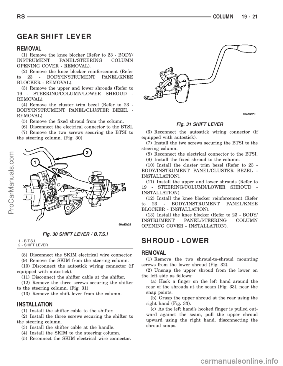
the steering column. (Fig. 30)
(8) Disconnect the SKIM electrical wire connector.
(9) Remove the SKIM from the steering column.
(10) Disconnect the autostick wiring connector (if
equipped with autostick).
(11) Disconnect the shifter cable at the shifter.
(12) Remove the three screws securing the shifter
to the steering column. (Fig. 31)
(13) Remove the shift lever from the column.
INSTALLATION
(1) Install the shifter cable to the shifter.
(2) Install the three screws securing the shifter to
the steering column.
(3) Install the shifter cable at the handle.
(4) Install the SKIM to the steering column.
(5) Reconnect the SKIM electrical wire connector.(6) Reconnect the autostick wiring connector (if
equipped with autostick).
(7) Install the two screws securing the BTSI to the
steering column.
(8) Reconnect the electrical connector to the BTSI.
(9) Install the fixed shroud to the column.
(10) Install the cluster trim bezel (Refer to 23 -
BODY/INSTRUMENT PANEL/CLUSTER BEZEL -
INSTALLATION).
(11) Install the upper and lower shrouds (Refer to
19 - STEERING/COLUMN/LOWER SHROUD -
INSTALLATION).
(12) Install the knee blocker reinforcement (Refer
to 23 - BODY/INSTRUMENT PANEL/KNEE
BLOCKER - INSTALLATION).
(13) Install the knee blocker (Refer to 23 - BODY/
INSTRUMENT PANEL/STEERING COLUMN
OPENING COVER - INSTALLATION).
SHROUD - LOWER
REMOVAL
(1) Remove the two shroud-to-shroud mounting
screws from the lower shroud (Fig. 32).
(2) Unsnap the upper shroud from the lower on
the left side as follows:
(a) Hook a finger on the left hand around the
rear of the shrouds at the seam (Fig. 33), near the
snap points.
(b) Grasp the upper shroud at the rear using the
right hand (Fig. 33).
(c) As the left hand's hooked finger is pulled out-
ward against the seam, pull the upper shroud
upward using the right hand, disconnecting the
shroud snaps.
Fig. 30 SHIFT LEVER / B.T.S.I
1 - B.T.S.I.
2 - SHIFT LEVER
Fig. 31 SHIFT LEVER
RSCOLUMN19-21
ProCarManuals.com
Page 1651 of 2177
(6) Pour four quarts of MopartATF+4 (Automatic
Transmission Fluid) through the dipstick opening.
(7) Start engine and allow to idle for at least one
minute. Then, with parking and service brakes
applied, move selector lever momentarily to each
position, ending in the park or neutral position.
(8) Check the transaxle fluid level and add an
appropriate amount to bring the transaxle fluid level
to 3mm (1/8 in.) below the lowest mark on the dip-
stick (Fig. 212).
(9) Recheck the fluid level after the transaxle has
reached normal operating temperature (180ÉF.).
(Refer to 21 - TRANSMISSION/TRANSAXLE/AUTO-
MATIC - 41TE/FLUID - STANDARD PROCEDURE)
(10) To prevent dirt from entering transaxle, make
certain that dipstick is fully seated into the dipstick
opening.
GEAR SHIFT CABLE
REMOVAL
(1) Disconnect battery cables.
(2) Remove battery shield.
(3) Remove battery.
(4) Remove speed control servo and position out of
way.
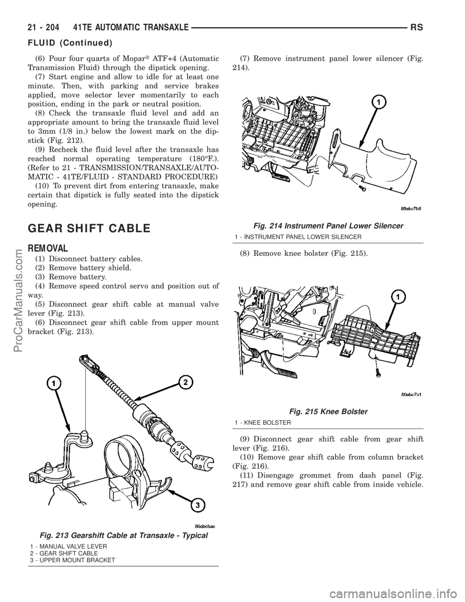
(5) Disconnect gear shift cable at manual valve
lever (Fig. 213).
(6) Disconnect gear shift cable from upper mount
bracket (Fig. 213).(7) Remove instrument panel lower silencer (Fig.
214).
(8) Remove knee bolster (Fig. 215).
(9) Disconnect gear shift cable from gear shift
lever (Fig. 216).
(10) Remove gear shift cable from column bracket
(Fig. 216).
(11) Disengage grommet from dash panel (Fig.
217) and remove gear shift cable from inside vehicle.
Fig. 213 Gearshift Cable at Transaxle - Typical
1 - MANUAL VALVE LEVER
2 - GEAR SHIFT CABLE
3 - UPPER MOUNT BRACKET
Fig. 214 Instrument Panel Lower Silencer
1 - INSTRUMENT PANEL LOWER SILENCER
Fig. 215 Knee Bolster
1 - KNEE BOLSTER
21 - 204 41TE AUTOMATIC TRANSAXLERS
FLUID (Continued)
ProCarManuals.com
Page 1653 of 2177
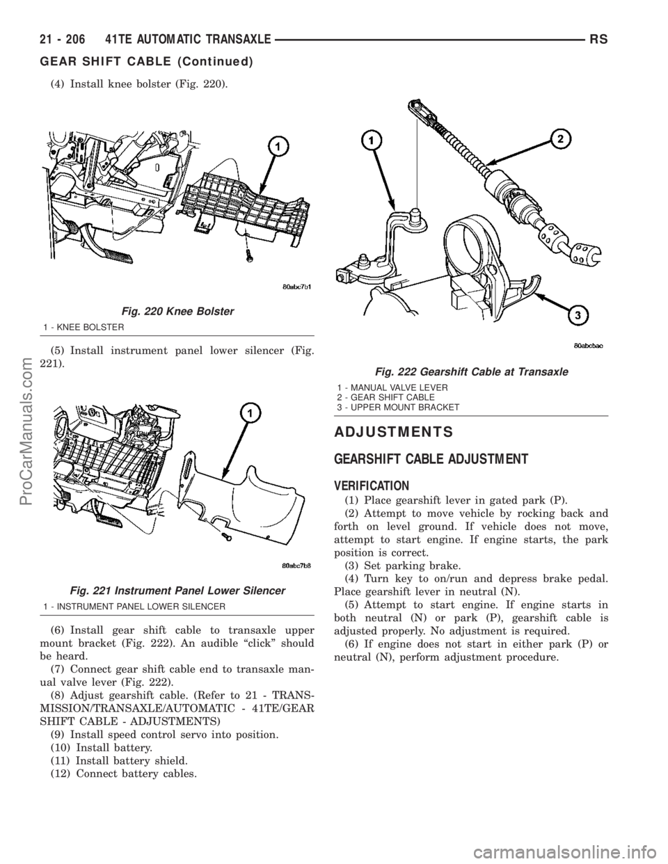
(4) Install knee bolster (Fig. 220).
(5) Install instrument panel lower silencer (Fig.
221).
(6) Install gear shift cable to transaxle upper
mount bracket (Fig. 222). An audible ªclickº should
be heard.
(7) Connect gear shift cable end to transaxle man-
ual valve lever (Fig. 222).
(8) Adjust gearshift cable. (Refer to 21 - TRANS-
MISSION/TRANSAXLE/AUTOMATIC - 41TE/GEAR
SHIFT CABLE - ADJUSTMENTS)
(9) Install speed control servo into position.
(10) Install battery.
(11) Install battery shield.
(12) Connect battery cables.
ADJUSTMENTS
GEARSHIFT CABLE ADJUSTMENT
VERIFICATION
(1) Place gearshift lever in gated park (P).
(2) Attempt to move vehicle by rocking back and
forth on level ground. If vehicle does not move,
attempt to start engine. If engine starts, the park
position is correct.
(3) Set parking brake.
(4) Turn key to on/run and depress brake pedal.
Place gearshift lever in neutral (N).
(5) Attempt to start engine. If engine starts in
both neutral (N) or park (P), gearshift cable is
adjusted properly. No adjustment is required.
(6) If engine does not start in either park (P) or
neutral (N), perform adjustment procedure.
Fig. 220 Knee Bolster
1 - KNEE BOLSTER
Fig. 221 Instrument Panel Lower Silencer
1 - INSTRUMENT PANEL LOWER SILENCER
Fig. 222 Gearshift Cable at Transaxle
1 - MANUAL VALVE LEVER
2 - GEAR SHIFT CABLE
3 - UPPER MOUNT BRACKET
21 - 206 41TE AUTOMATIC TRANSAXLERS
GEAR SHIFT CABLE (Continued)
ProCarManuals.com
Page 1682 of 2177
DIAGNOSIS AND TESTING - BRAKE/
TRANSMISSION SHIFT INTERLOCK SOLENOID
For intended BTSI system operation, refer to the
following chart:
ACTION EXPECTED RESPONSE
1. Turn key to the9OFF9
position.1. Shifter CAN be shifted
out of park with brake
pedal applied.
2. Turn key to the
9ON/RUN9position.2. Shifter CANNOT be
shifted out of park.
3. Turn key to the
9ON/RUN9position and
depress the brake pedal.3. Shifter CAN be shifted
out of park.
4. Leave shifter in any
gear and try to return key
to the9LOCK9or9ACC9
position.4. Key cannot be
returned to the9LOCK9or
9ACC9position.
5. Return shifter to
9PARK9and try to remove
the key.5. Key can be removed
(after returning to9LOCK9
position).
6. With the key removed,
try to shift out of9PARK9.6. Shifter cannot be
shifted out of9PARK9.
NOTE: Any failure to meet these expected
responses requires system repair. Refer to the
appropriate Diagnostic Information.
REMOVAL
(1) Disconnect battery negative cable.
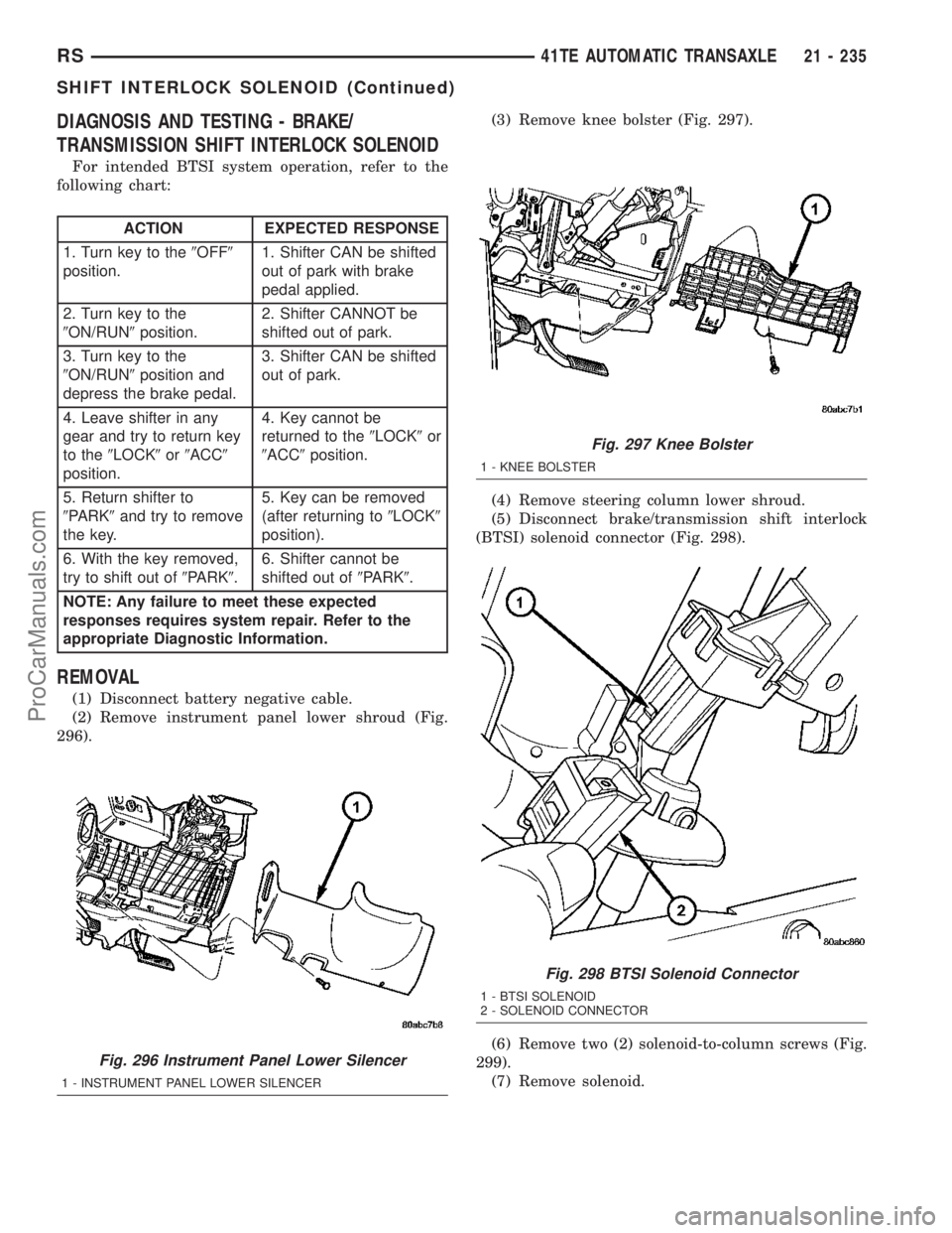
(2) Remove instrument panel lower shroud (Fig.
296).(3) Remove knee bolster (Fig. 297).
(4) Remove steering column lower shroud.
(5) Disconnect brake/transmission shift interlock
(BTSI) solenoid connector (Fig. 298).
(6) Remove two (2) solenoid-to-column screws (Fig.
299).
(7) Remove solenoid.
Fig. 296 Instrument Panel Lower Silencer
1 - INSTRUMENT PANEL LOWER SILENCER
Fig. 297 Knee Bolster
1 - KNEE BOLSTER
Fig. 298 BTSI Solenoid Connector
1 - BTSI SOLENOID
2 - SOLENOID CONNECTOR
RS41TE AUTOMATIC TRANSAXLE21 - 235
SHIFT INTERLOCK SOLENOID (Continued)
ProCarManuals.com
Page 1684 of 2177
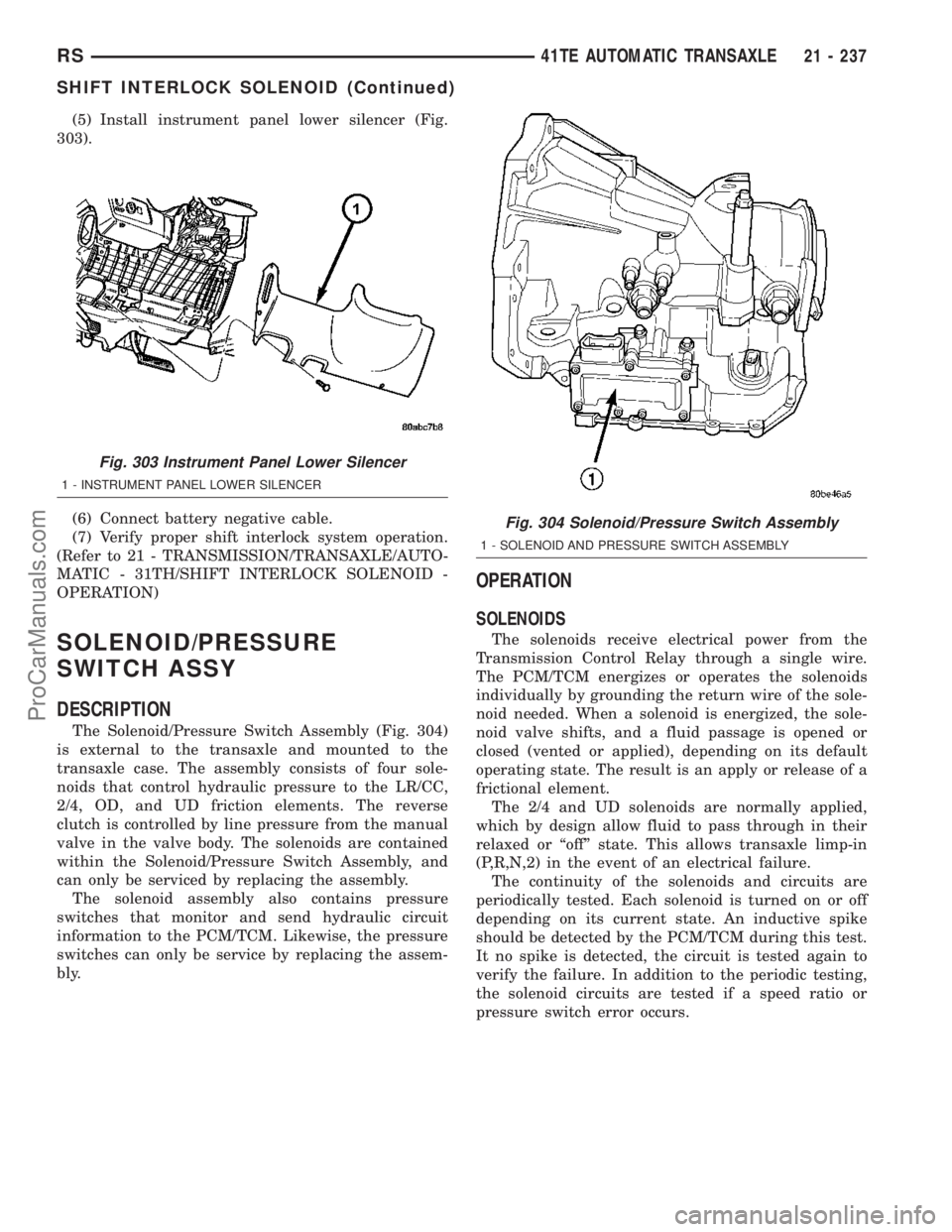
(5) Install instrument panel lower silencer (Fig.
303).
(6) Connect battery negative cable.
(7) Verify proper shift interlock system operation.
(Refer to 21 - TRANSMISSION/TRANSAXLE/AUTO-
MATIC - 31TH/SHIFT INTERLOCK SOLENOID -
OPERATION)
SOLENOID/PRESSURE
SWITCH ASSY
DESCRIPTION
The Solenoid/Pressure Switch Assembly (Fig. 304)
is external to the transaxle and mounted to the
transaxle case. The assembly consists of four sole-
noids that control hydraulic pressure to the LR/CC,
2/4, OD, and UD friction elements. The reverse
clutch is controlled by line pressure from the manual
valve in the valve body. The solenoids are contained
within the Solenoid/Pressure Switch Assembly, and
can only be serviced by replacing the assembly.
The solenoid assembly also contains pressure
switches that monitor and send hydraulic circuit
information to the PCM/TCM. Likewise, the pressure
switches can only be service by replacing the assem-
bly.
OPERATION
SOLENOIDS
The solenoids receive electrical power from the
Transmission Control Relay through a single wire.
The PCM/TCM energizes or operates the solenoids
individually by grounding the return wire of the sole-
noid needed. When a solenoid is energized, the sole-
noid valve shifts, and a fluid passage is opened or
closed (vented or applied), depending on its default
operating state. The result is an apply or release of a
frictional element.
The 2/4 and UD solenoids are normally applied,
which by design allow fluid to pass through in their
relaxed or ªoffº state. This allows transaxle limp-in
(P,R,N,2) in the event of an electrical failure.
The continuity of the solenoids and circuits are
periodically tested. Each solenoid is turned on or off
depending on its current state. An inductive spike
should be detected by the PCM/TCM during this test.
It no spike is detected, the circuit is tested again to
verify the failure. In addition to the periodic testing,
the solenoid circuits are tested if a speed ratio or
pressure switch error occurs.
Fig. 303 Instrument Panel Lower Silencer
1 - INSTRUMENT PANEL LOWER SILENCER
Fig. 304 Solenoid/Pressure Switch Assembly
1 - SOLENOID AND PRESSURE SWITCH ASSEMBLY
RS41TE AUTOMATIC TRANSAXLE21 - 237
SHIFT INTERLOCK SOLENOID (Continued)
ProCarManuals.com
Page 1734 of 2177
BODY
TABLE OF CONTENTS
page page
BODY
DESCRIPTION - VEHICLE IDENTIFICATION....1
WARNING
SAFETY PRECAUTIONS AND WARNINGS . . . 1
DIAGNOSIS AND TESTING
DIAGNOSIS AND TESTING - WATER LEAKS . 2
DIAGNOSIS AND TESTING - WIND NOISE . . . 3
STANDARD PROCEDURE
STANDARD PROCEDURE - PLASTIC BODY
PANEL REPAIR........................3
STANDARD PROCEDURE - HEAT STAKING . 10
SPECIFICATIONS
TORQUE............................11
BODY LUBRICATION...................12
SPECIAL TOOLS
BODY..............................13DOOR - FRONT.........................14
DOORS - SLIDING.......................24
DECKLID/HATCH/LIFTGATE/TAILGATE.......39
EXTERIOR.............................44
HOOD.................................59
INSTRUMENT PANEL.....................62
INTERIOR..............................72
PAINT.................................83
SEATS................................85
STATIONARY GLASS....................105
WEATHERSTRIP/SEALS..................110
SUNROOF.............................113
BODY STRUCTURE.....................121
BODY
DESCRIPTION - VEHICLE IDENTIFICATION
Throughout this group, references to the
DaimlerChrysler Corporation vehicle family identifi-
cation code are used when describing a procedure
that is unique to that vehicle. Refer to Introduction
Group of this manual for detailed information on
vehicle identification. If a procedure is common to all
vehicles covered in this manual, no reference will be
made to a vehicle family code.
WARNING
SAFETY PRECAUTIONS AND WARNINGS
WARNING: USE A OSHA APPROVED BREATHING
FILTER WHEN SPRAYING PAINT OR SOLVENTS IN
A CONFINED AREA. PERSONAL INJURY CAN
RESULT.
AVOID PROLONGED SKIN CONTACT WITH PETRO-
LEUM OR ALCOHOL ± BASED CLEANING SOL-
VENTS. PERSONAL INJURY CAN RESULT.
DO NOT STAND UNDER A HOISTED VEHICLE THATIS NOT PROPERLY SUPPORTED ON SAFETY
STANDS. PERSONAL INJURY CAN RESULT.
CAUTION: When holes must be drilled or punched
in an inner body panel, verify depth of space to the
outer body panel, electrical wiring, or other compo-
nents. Damage to vehicle can result.
Do not weld exterior panels unless combustible
material on the interior of vehicle is removed from
the repair area. Fire or hazardous conditions, can
result.
Always have a fire extinguisher ready for use when
welding.
Disconnect the negative (-) cable clamp from the
battery when servicing electrical components that
are live when the ignition is OFF. Damage to electri-
cal system can result.
Do not use abrasive chemicals or compounds on
painted surfaces. Damage to finish can result.
Do not use harsh alkaline based cleaning solvents
on painted or upholstered surfaces. Damage to fin-
ish or color can result.
Do not hammer or pound on plastic trim panel
when servicing interior trim. Plastic panels can
break.
RSBODY23-1
ProCarManuals.com