2003 CHRYSLER CARAVAN door lock
[x] Cancel search: door lockPage 1785 of 2177
(8) Verify that all clips on fuel filler housing are
fully engaged to outer quarter panel.
(9) Place fuel fill neck in position.
(10) Install screws to hold fuel fill neck to fuel
filler housing.
(11) Engage latch release link into clip on fuel fill
blocker latch arm.
(12) Verify fuel fill blocker latch operation.
(13) Install water shield patch to cover access hole
in C-pillar.
(14) Install left quarter trim panel.
FUEL FILL DOOR BLOCKER
LATCH
REMOVAL
(1) Remove left quarter trim panel.
(2) Remove water shield patch covering access hole
in C-pillar.
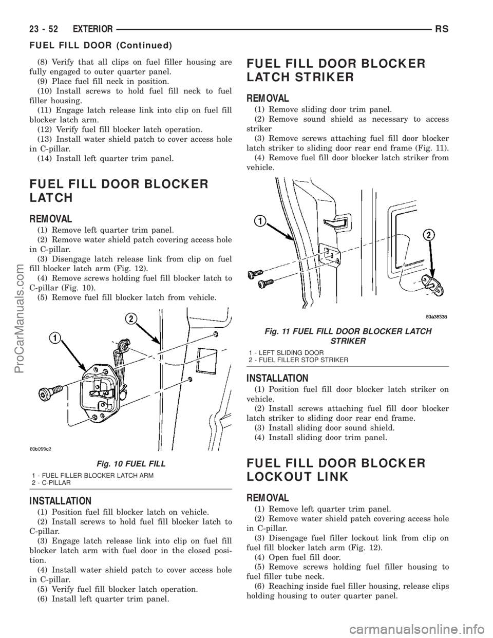
(3) Disengage latch release link from clip on fuel
fill blocker latch arm (Fig. 12).
(4) Remove screws holding fuel fill blocker latch to
C-pillar (Fig. 10).
(5) Remove fuel fill blocker latch from vehicle.
INSTALLATION
(1) Position fuel fill blocker latch on vehicle.
(2) Install screws to hold fuel fill blocker latch to
C-pillar.
(3) Engage latch release link into clip on fuel fill
blocker latch arm with fuel door in the closed posi-
tion.
(4) Install water shield patch to cover access hole
in C-pillar.
(5) Verify fuel fill blocker latch operation.
(6) Install left quarter trim panel.
FUEL FILL DOOR BLOCKER
LATCH STRIKER
REMOVAL
(1) Remove sliding door trim panel.
(2) Remove sound shield as necessary to access
striker
(3) Remove screws attaching fuel fill door blocker
latch striker to sliding door rear end frame (Fig. 11).
(4) Remove fuel fill door blocker latch striker from
vehicle.
INSTALLATION
(1) Position fuel fill door blocker latch striker on
vehicle.
(2) Install screws attaching fuel fill door blocker
latch striker to sliding door rear end frame.
(3) Install sliding door sound shield.
(4) Install sliding door trim panel.
FUEL FILL DOOR BLOCKER
LOCKOUT LINK
REMOVAL
(1) Remove left quarter trim panel.
(2) Remove water shield patch covering access hole
in C-pillar.
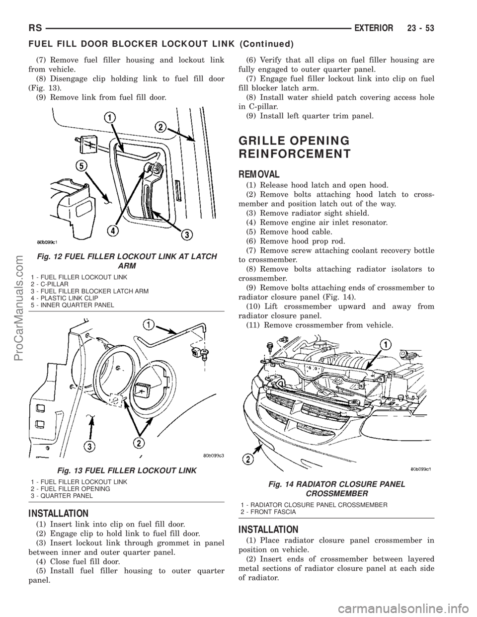
(3) Disengage fuel filler lockout link from clip on
fuel fill blocker latch arm (Fig. 12).
(4) Open fuel fill door.
(5) Remove screws holding fuel filler housing to
fuel filler tube neck.
(6) Reaching inside fuel filler housing, release clips
holding housing to outer quarter panel.
Fig. 10 FUEL FILL
1 - FUEL FILLER BLOCKER LATCH ARM
2 - C-PILLAR
Fig. 11 FUEL FILL DOOR BLOCKER LATCH
STRIKER
1 - LEFT SLIDING DOOR
2 - FUEL FILLER STOP STRIKER
23 - 52 EXTERIORRS
FUEL FILL DOOR (Continued)
ProCarManuals.com
Page 1786 of 2177
(7) Remove fuel filler housing and lockout link
from vehicle.
(8) Disengage clip holding link to fuel fill door
(Fig. 13).
(9) Remove link from fuel fill door.
INSTALLATION
(1) Insert link into clip on fuel fill door.
(2) Engage clip to hold link to fuel fill door.
(3) Insert lockout link through grommet in panel
between inner and outer quarter panel.
(4) Close fuel fill door.
(5) Install fuel filler housing to outer quarter
panel.(6) Verify that all clips on fuel filler housing are
fully engaged to outer quarter panel.
(7) Engage fuel filler lockout link into clip on fuel
fill blocker latch arm.
(8) Install water shield patch covering access hole
in C-pillar.
(9) Install left quarter trim panel.
GRILLE OPENING
REINFORCEMENT
REMOVAL
(1) Release hood latch and open hood.
(2) Remove bolts attaching hood latch to cross-
member and position latch out of the way.
(3) Remove radiator sight shield.
(4) Remove engine air inlet resonator.
(5) Remove hood cable.
(6) Remove hood prop rod.
(7) Remove screw attaching coolant recovery bottle
to crossmember.
(8) Remove bolts attaching radiator isolators to
crossmember.
(9) Remove bolts attaching ends of crossmember to
radiator closure panel (Fig. 14).
(10) Lift crossmember upward and away from
radiator closure panel.
(11) Remove crossmember from vehicle.
INSTALLATION
(1) Place radiator closure panel crossmember in
position on vehicle.
(2) Insert ends of crossmember between layered
metal sections of radiator closure panel at each side
of radiator.
Fig. 12 FUEL FILLER LOCKOUT LINK AT LATCH
ARM
1 - FUEL FILLER LOCKOUT LINK
2 - C-PILLAR
3 - FUEL FILLER BLOCKER LATCH ARM
4 - PLASTIC LINK CLIP
5 - INNER QUARTER PANEL
Fig. 13 FUEL FILLER LOCKOUT LINK
1 - FUEL FILLER LOCKOUT LINK
2 - FUEL FILLER OPENING
3 - QUARTER PANELFig. 14 RADIATOR CLOSURE PANEL
CROSSMEMBER
1 - RADIATOR CLOSURE PANEL CROSSMEMBER
2 - FRONT FASCIA
RSEXTERIOR23-53
FUEL FILL DOOR BLOCKER LOCKOUT LINK (Continued)
ProCarManuals.com
Page 1789 of 2177
INSTALLATION
NOTE: The crossbar assemblies are designed to be
installed in only one way. Check top and bottom
surfaces of the crossbar for the word FRONT and
directional arrows. The directional arrows must
point toward the front of the vehicle.
(1) Place crossbar in position on vehicle.
(2) Work from side to side sliding the crossbar
assembly back a little at a time to ensure it remains
perpendicular to the side rails.
(3) Position first crossbar assembly crossbar at the
second most rearward locator holes. Press the top of
the stanchion lever to lock it into position.
(4) Position the second crossbar assembly in the
second hole from the front. Lock into place.
(5) Place luggage rack riser into position.
(6) Install two fasteners into riser. Tighten fasten-
ers to 4 mm (35 in. lbs.) torque.
REAR QUARTER PANEL/
FENDER AIR EXHAUSTER
DESCRIPTION
Air exhausters, designed to conform to the body
structure, allow air entering at the front of the vehi-
cle to flow out the back. By reducing air pressure
within the vehicle, the exhausters also reduce blower
noise at any given air flow level compared to operat-
ing without them and help reduce door closing effort.
They are located in the lower rear comers of the
body.
REMOVAL
SHORT WHEELBASE
(1) Remove the rear fascia from the body. (Refer to
13 - FRAMES & BUMPERS/BUMPERS/REAR FAS-
CIA - REMOVAL).
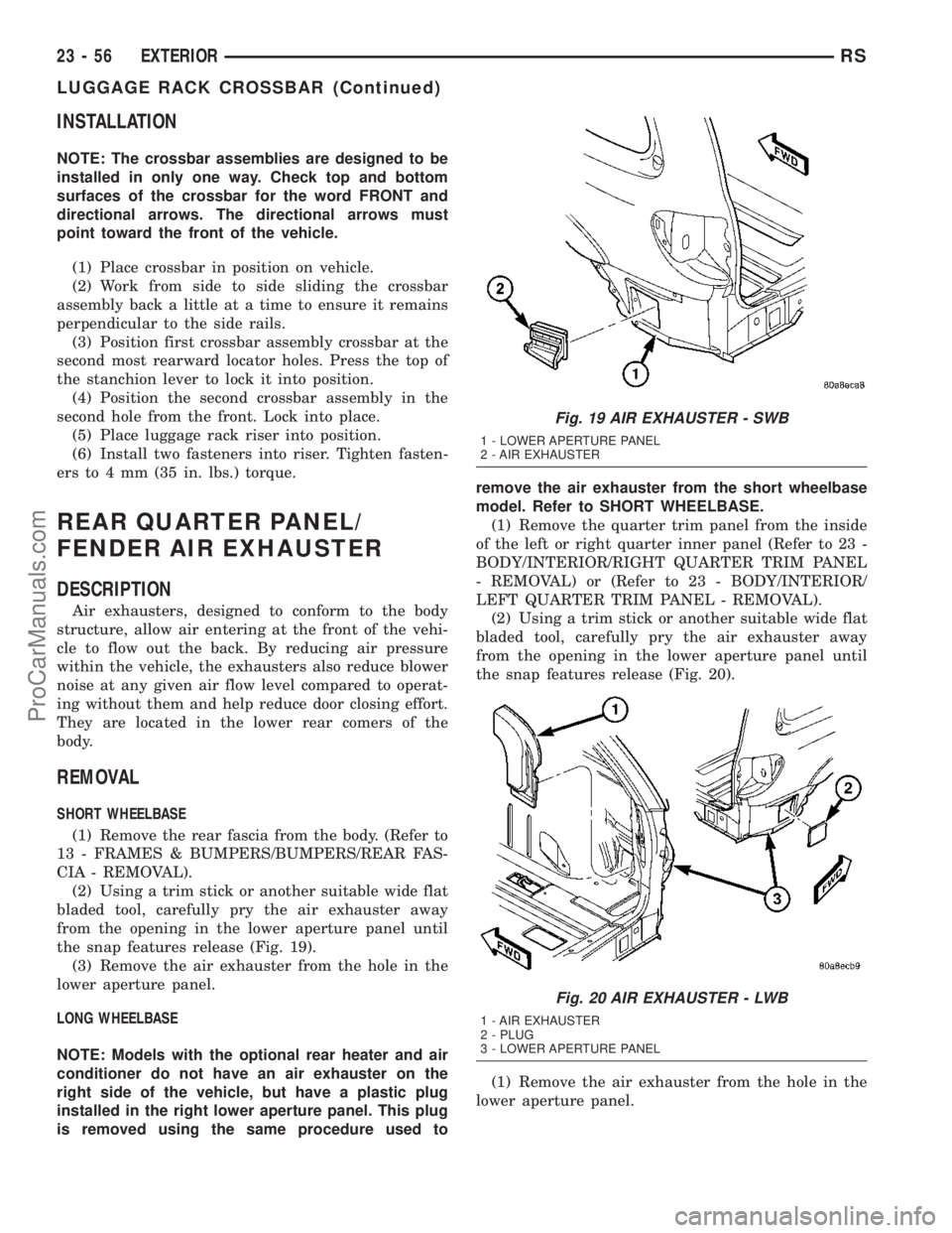
(2) Using a trim stick or another suitable wide flat
bladed tool, carefully pry the air exhauster away
from the opening in the lower aperture panel until
the snap features release (Fig. 19).
(3) Remove the air exhauster from the hole in the
lower aperture panel.
LONG WHEELBASE
NOTE: Models with the optional rear heater and air
conditioner do not have an air exhauster on the
right side of the vehicle, but have a plastic plug
installed in the right lower aperture panel. This plug
is removed using the same procedure used toremove the air exhauster from the short wheelbase
model. Refer to SHORT WHEELBASE.
(1) Remove the quarter trim panel from the inside
of the left or right quarter inner panel (Refer to 23 -
BODY/INTERIOR/RIGHT QUARTER TRIM PANEL
- REMOVAL) or (Refer to 23 - BODY/INTERIOR/
LEFT QUARTER TRIM PANEL - REMOVAL).
(2) Using a trim stick or another suitable wide flat
bladed tool, carefully pry the air exhauster away
from the opening in the lower aperture panel until
the snap features release (Fig. 20).
(1) Remove the air exhauster from the hole in the
lower aperture panel.
Fig. 19 AIR EXHAUSTER - SWB
1 - LOWER APERTURE PANEL
2 - AIR EXHAUSTER
Fig. 20 AIR EXHAUSTER - LWB
1 - AIR EXHAUSTER
2 - PLUG
3 - LOWER APERTURE PANEL
23 - 56 EXTERIORRS
LUGGAGE RACK CROSSBAR (Continued)
ProCarManuals.com
Page 1797 of 2177
GLOVE BOX LATCH STRIKER
REMOVAL
(1) Open glove box door.
(2) Remove screws holding lock striker to instru-
ment panel.
(3) Remove glove box latch striker.
INSTALLATION
(1) Install the glove box latch striker.
(2) Install the screws holding latch striker to
instrument panel.
(3) Close glove box door.
INSTRUMENT PANEL
ASSEMBLY
REMOVAL
(1) Disconnect and isolate the battery negative
cable.
(2) Remove the lower console:
(a) Remove six retaining screws.
(b) Pull rearward and disconnect the auxiliary
power outlet.
(c) Remove lower console from vehicle.
(3) Remove the bolts attaching the lower supports
to the instrument panel frame (Fig. 3).
(4) Remove the bolts attaching the lower supports
to the floor pan.
(5) Disconnect the wire connectors from the Pas-
senger Airbag.
(6) Remove the two screws to each right and left
cowl trim covers.
(7) Remove the both left and right side A-pillar
trim covers using a trim stick (special tool #C-4755)
or equivalent gently pry out on the trim covers and
remove.
(8) Remove the glove box:
(a) Push in on sides of glove box bin and lower
door.
(b) Pivot glove box downward and disengage
hinge hooks from instrument panel.
(c) Remove glove box from vehicle.
(9) Disconnect the antenna lead connector from
behind the glove box.
(10) Remove the four screws to the lower steering
column cover.
(11) Remove the eight screws to the steering col-
umn backing plate.
(12) Unclip the Data Link Connector (DLC) from
the steering column backing plate.
(13) Disconnect the left side wiring:
(a) Brake switch.
(b) Main bulkhead connector.(c) Five harness connectors.
(d) Driver airbag connector.
(14) Remove the two screws to the hood release
handle.
(15) Remove five screws to steering column back-
ing plate and remove (Refer to 23 - BODY/INSTRU-
MENT PANEL/KNEE BLOCKER - REMOVAL).
(16) Remove the two steering column shroud
retaining screws. Separate the shrouds and remove
from vehicle.
(17) Remove the screws attaching the instrument
panel reinforcement and remove (Fig. 4).
(18) Disconnect the steering column wiring. There
are seven connectors and then unclip the harness
from the column.
(19) Disconnect the Occupant Restraint Controller
(ORC) harness connector.
(20) Remove the four nuts retaining the steering
column to the dash panel steering column mounting
bracket and lower column to the floor (Fig. 5).
(21) Remove the four nuts attaching the instru-
ment panel to the brake pedal support bracket.
(22) Loosen the left side roll down bolt (Fig. 6).
(23) Remove the left side A-pillar retaining bolts.
There are two 13 mm bolts and one 10 mm bolt.
(24) If equipped with a mechanical transmission
range indicator:
(a) Remove the indicator cable loop.
(b) Remove the clip holding gear shift cable end
to the gear selector adapter.
(c) Pull the cable end from gear selector.
(d) Disconnect the clip for the indicator cable
and guide tube from the shift cable bracket and
move out of the way.
(25) Remove the instrument panel top cover. Using
a trim stick or equivalent, gently pry up on the front
edge of the top cover, pull rearward and remove from
vehicle.
(26) Disconnect the right side wire connectors from
the HVAC behind the glove box area and the two
antenna connectors behind the glove box hinge.
(27) Remove the right end cover by pulling out-
board.
(28) Remove the right side A-pillar retaining bolts.
There are two 13 mm bolts and one 10 mm bolt.
(29) Loosen the right side roll down bolt.
(30) Disconnect the two front window defroster
grid wire connectors. One on each side of vehicle.
(31) Remove both the left and right power mirrors:
(a) Using a trim stick or equivalent, gently pry
out on mirror trim cover.
(b) Open door and remove the three torx retain-
ing screws.
(c) Disconnect the wire connector and remove
mirror from the vehicle.
23 - 64 INSTRUMENT PANELRS
ProCarManuals.com
Page 1809 of 2177
INSTALLATION
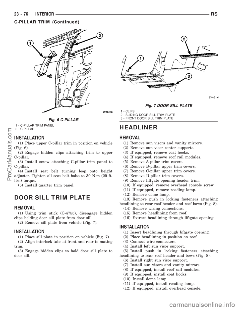
(1) Place upper C-pillar trim in position on vehicle
(Fig. 6).
(2) Engage hidden clips attaching trim to upper
C-pillar.
(3) Install screw attaching C-pillar trim panel to
C-pillar.
(4) Install seat belt turning loop onto height
adjuster. Tighten all seat belt bolts to 39 N´m (29 ft.
lbs.) torque.
(5) Install quarter trim panel.
DOOR SILL TRIM PLATE
REMOVAL
(1) Using trim stick (C-4755), disengage hidden
clips holding door sill plate from door sill.
(2) Remove sill plate from vehicle (Fig. 7).
INSTALLATION
(1) Place sill plate in position on vehicle (Fig. 7).
(2) Align interlock tabs at front and rear to mating
trim.
(3) Engage hidden clips to hold door sill plate to
door sill.
HEADLINER
REMOVAL
(1) Remove sun visors and vanity mirrors.
(2) Remove sun visor center supports.
(3) If equipped, remove coat hooks.
(4) If equipped, remove roof rail modules.
(5) Remove A-pillar trim covers.
(6) Remove B-pillar upper trim covers.
(7) Remove C-pillar upper trim covers.
(8) Remove D-pillar trim covers.
(9) Remove liftgate opening header trim.
(10) If equipped, remove overhead console screw.
(11) If equipped, remove reading lamp.
(12) Remove dome lamp.
(13) Remove push in locking fasteners attaching
headlining to rear roof header and roof bows (Fig. 8).
(14) Remove wiring connections.
(15) Remove headlining from roof.
(16) Extract headlining through liftgate opening.
INSTALLATION
(1) Insert headlining through liftgate opening.
(2) Place headlining in position on roof.
(3) Connect wire connectors.
(4) Install left sun visor support.
(5) Install push in locking fasteners attaching
headlining to rear roof header and bows (Fig. 8).
(6) Install right sun visor support.
(7) Install sun visors and vanity mirrors.
(8) If equipped, install roof rail modules.
(9) If equipped, install coat hooks.
(10) Install dome lamp.
(11) If equipped, install reading lamp.
(12) If equipped, install overhead console.
Fig. 6 C-PILLAR
1 - C-PILLAR TRIM PANEL
2 - C-PILLAR
Fig. 7 DOOR SILL PLATE
1 - CLIPS
2 - SLIDING DOOR SILL TRIM PLATE
3 - FRONT DOOR SILL TRIM PLATE
23 - 76 INTERIORRS
C-PILLAR TRIM (Continued)
ProCarManuals.com
Page 1812 of 2177
(6) Position quarter trim panel on inner quarter
panel.
(7) Install screws attaching rear edge of quarter
trim to attaching bracket or inner quarter panel.
(8) Install screws attaching quarter trim to inner
quarter panel in bolster area.
(9) Install second row seat belts anchor on long
wheel base vehicle. Tighten all seat belt bolts to 39
N´m (28 in. lbs.) torque.
(10) Install first row seat belt anchor.
(11) Install left D-pillar trim panel.
(12) Install C-pillar trim panel.
(13) Install upper left B-pillar trim on three door
vehicle.
(14) Install left quarter trim bolster.
(15) Install front door sill plate on three door vehi-
cle.
(16) Install sliding door sill plate on four door
vehicle.
(17) Install second row seat, if equipped.
(18) Install first row seat.
(19) Connect the battery negative cable.
REAR HEADER TRIM
REMOVAL
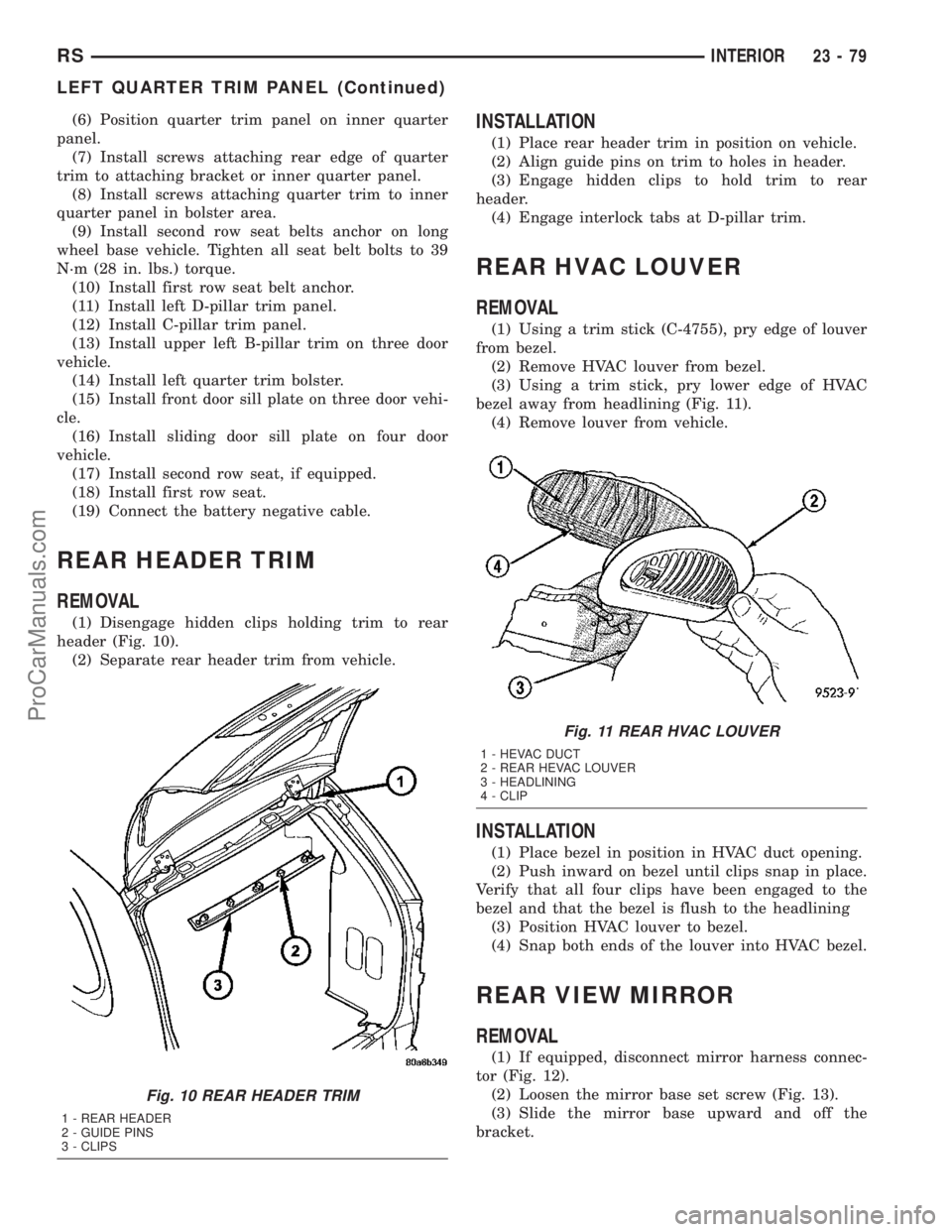
(1) Disengage hidden clips holding trim to rear
header (Fig. 10).
(2) Separate rear header trim from vehicle.
INSTALLATION
(1) Place rear header trim in position on vehicle.
(2) Align guide pins on trim to holes in header.
(3) Engage hidden clips to hold trim to rear
header.
(4) Engage interlock tabs at D-pillar trim.
REAR HVAC LOUVER
REMOVAL
(1) Using a trim stick (C-4755), pry edge of louver
from bezel.
(2) Remove HVAC louver from bezel.
(3) Using a trim stick, pry lower edge of HVAC
bezel away from headlining (Fig. 11).
(4) Remove louver from vehicle.
INSTALLATION
(1) Place bezel in position in HVAC duct opening.
(2) Push inward on bezel until clips snap in place.
Verify that all four clips have been engaged to the
bezel and that the bezel is flush to the headlining
(3) Position HVAC louver to bezel.
(4) Snap both ends of the louver into HVAC bezel.
REAR VIEW MIRROR
REMOVAL
(1) If equipped, disconnect mirror harness connec-
tor (Fig. 12).
(2) Loosen the mirror base set screw (Fig. 13).
(3) Slide the mirror base upward and off the
bracket.
Fig. 10 REAR HEADER TRIM
1 - REAR HEADER
2 - GUIDE PINS
3 - CLIPS
Fig. 11 REAR HVAC LOUVER
1 - HEVAC DUCT
2 - REAR HEVAC LOUVER
3 - HEADLINING
4 - CLIP
RSINTERIOR23-79
LEFT QUARTER TRIM PANEL (Continued)
ProCarManuals.com
Page 1814 of 2177
(2) Engage hooks to hold outside edge of sill plate
to door sill.
(3) Align guide pins to holes in door sill.
(4) Engage hidden clips to hold sill plate to sliding
door opening sill.
(5) Engage interlock tabs at lower B-pillar and
quarter trim panel.
SUN VISOR
REMOVAL
All vehicles with driver and passenger side air
bags must have a colored coded five Bullet point air
bag warning label applied to the sun visor, verify
label availability and ensure the label is installed.
(1) Disengage sun visor from center support.
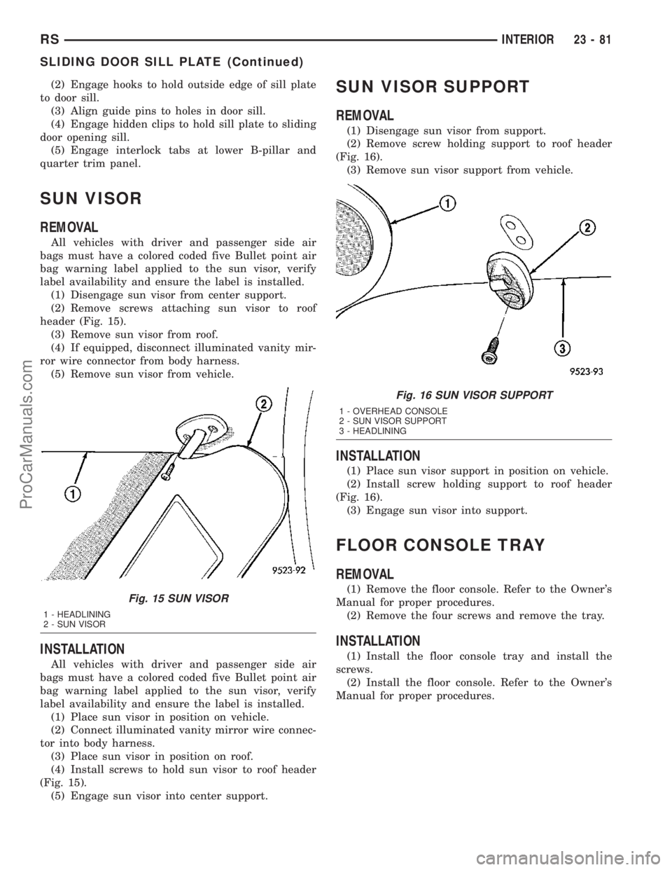
(2) Remove screws attaching sun visor to roof
header (Fig. 15).
(3) Remove sun visor from roof.
(4) If equipped, disconnect illuminated vanity mir-
ror wire connector from body harness.
(5) Remove sun visor from vehicle.
INSTALLATION
All vehicles with driver and passenger side air
bags must have a colored coded five Bullet point air
bag warning label applied to the sun visor, verify
label availability and ensure the label is installed.
(1) Place sun visor in position on vehicle.
(2) Connect illuminated vanity mirror wire connec-
tor into body harness.
(3) Place sun visor in position on roof.
(4) Install screws to hold sun visor to roof header
(Fig. 15).
(5) Engage sun visor into center support.
SUN VISOR SUPPORT
REMOVAL
(1) Disengage sun visor from support.
(2) Remove screw holding support to roof header
(Fig. 16).
(3) Remove sun visor support from vehicle.
INSTALLATION
(1) Place sun visor support in position on vehicle.
(2) Install screw holding support to roof header
(Fig. 16).
(3) Engage sun visor into support.
FLOOR CONSOLE TRAY
REMOVAL
(1) Remove the floor console. Refer to the Owner's
Manual for proper procedures.
(2) Remove the four screws and remove the tray.
INSTALLATION
(1) Install the floor console tray and install the
screws.
(2) Install the floor console. Refer to the Owner's
Manual for proper procedures.
Fig. 15 SUN VISOR
1 - HEADLINING
2 - SUN VISOR
Fig. 16 SUN VISOR SUPPORT
1 - OVERHEAD CONSOLE
2 - SUN VISOR SUPPORT
3 - HEADLINING
RSINTERIOR23-81
SLIDING DOOR SILL PLATE (Continued)
ProCarManuals.com
Page 1839 of 2177
(4) Remove A-pillar trim panels.
(5) Place protective covers over instrument panel
and hood.
(6) Remove windshield molding. Using pliers, pull
outward on molding at the bottom of A-pillars.
(7) Using a sharp cold knife, cut urethane adhe-
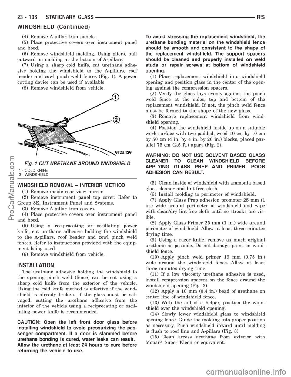
sive holding the windshield to the A-pillars, roof
header and cowl pinch weld fences (Fig. 1). A power
cutting device can be used if available.
(8) Remove windshield from vehicle.
WINDSHIELD REMOVAL ± INTERIOR METHOD
(1) Remove inside rear view mirror.
(2) Remove instrument panel top cover. Refer to
Group 8E, Instrument Panel and Systems.
(3) Remove A-pillar trim covers.
(4) Place protective covers over instrument panel
and hood.
(5) Using a reciprocating or oscillating power
knife, cut urethane adhesive holding the windshield
to the A-pillars, roof header and cowl pinch weld
fences. Refer to instructions provided with the equip-
ment being used.
(6) Remove windshield from vehicle.
INSTALLATION
The urethane adhesive holding the windshield to
the opening pinch weld (fence) can be cut using a
sharp cold knife from the exterior of the vehicle.
Using the cold knife method is effective if the wind-
shield is already broken. If the glass must be sal-
vaged, cutting the urethane adhesive from the
interior of the vehicle using a reciprocating or oscil-
lating power knife is recommended.
CAUTION: Open the left front door glass before
installing windshield to avoid pressurizing the pas-
senger compartment. If a door is slammed before
urethane bonding is cured, water leaks can result.
Allow the urethane at least 24 hours to cure before
returning the vehicle to use.To avoid stressing the replacement windshield, the
urethane bonding material on the windshield fence
should be smooth and consistent to the shape of
the replacement windshield. The support spacers
should be cleaned and properly installed on weld
studs or repair screws at bottom of windshield
opening.
(1) Place replacement windshield into windshield
opening and position glass in the center of the open-
ing against the compression spacers.
(2) Verify the glass lays evenly against the pinch
weld fence at the sides, top and bottom of the
replacement windshield. If not, the pinch weld fence
must be formed to the shape of the new glass.
(3) Remove replacement windshield from wind-
shield opening.
(4) Position the windshield inside up on a suitable
work surface with two padded, wood 10 cm by 10 cm
by 50 cm (4 in. by 4 in. by 20 in.) blocks, placed par-
allel 75 cm (2.5 ft.) apart (Fig. 2).
WARNING: DO NOT USE SOLVENT BASED GLASS
CLEANER TO CLEAN WINDSHIELD BEFORE
APPLYING GLASS PREP AND PRIMER. POOR
ADHESION CAN RESULT.
(5) Clean inside of windshield with ammonia based
glass cleaner and lint-free cloth.
(6) Install molding to perimeter of windshield.
(7) Apply Glass Prep adhesion promoter 25 mm (1
in.) wide around perimeter of windshield and wipe
with clean/dry lint-free cloth until no streaks are vis-
ible.
(8) Apply Glass Primer 25 mm (1 in.) wide around
perimeter of windshield. Allow at least three minutes
drying time.
(9) Using a razor knife, remove as much original
urethane as possible. Do not damage paint on wind-
shield fence.
(10) Apply pinch weld primer 19 mm (0.75 in.)
wide around the windshield fence. Allow at least
three minutes drying time.
(11) If a low viscosity urethane adhesive is used,
install compression spacers on the fence around the
windshield opening (Fig. 3).
(12) Apply a 10 mm (0.4 in.) bead of urethane on
center line of windshield fence.
(13) With the aid of a helper, position the wind-
shield over the windshield opening.
(14) Slowly lower windshield glass to windshield
opening fence. Guide the molding into proper position
as necessary. Push windshield inward until molding
is flush to roof line and A-pillars (Fig. 3).
(15) Clean access urethane from exterior with
MopartSuper Kleen or equivalent.
Fig. 1 CUT URETHANE AROUND WINDSHIELD
1 - COLD KNIFE
2 - WINDSHIELD
23 - 106 STATIONARY GLASSRS
WINDSHIELD (Continued)
ProCarManuals.com