2003 CHRYSLER CARAVAN wheel torque
[x] Cancel search: wheel torquePage 1427 of 2177
NOTE: The next step must be done to allow the
removal of the steering gear from the front suspen-
sion cradle. The steering gear cannot be removed
from the vehicle with the intermediate coupler
attached to the steering gear.
(19) Lower steering gear from suspension cradle
enough to allow access to the intermediate coupler
roll pin (Fig. 9). Install Remover/Installer, Special
Tool 6831A, through the center of the roll pin, secur-
ing with the knurled nut (Fig. 9). Hold threaded rod
stationary while turning nut, this will pull the roll
pin out of the intermediate coupler.
(20) Separate the coupler from the steering gear
shaft.
(21) Remove the power steering gear from the
vehicle.
INSTALLATION
INSTALLATION - LHD GEAR
(1) Install the power steering gear up in the front
suspension cradle, leaving room to install intermedi-
ate coupler.
(2) Start the roll pin into the intermediate coupler
before installing coupler on steering gear shaft. Start
roll pin into coupler, using a hammer and tapping it
into the coupler. Then install the intermediate cou-
pler on the shaft of the steering gear.
(3) Install Remover/Installer Special Tool 6831A
through the center of the roll pin, securing it with
the knurled nut (Fig. 12). Hold threaded rod station-
ary while turning nut, this will pull the roll pin into
the intermediate coupler.
CAUTION: Proper torque on the steering gear to
suspension cradle mounting bolts is very impor-
tant.
(4) Install steering gear on the front suspension
cradle. Install the 3 steering gear mounting bolts and
nuts (Fig. 8). Tighten the 3 mounting bolts to the fol-
lowing torque values:
²14 mm bolt ± 183 N´m (135 ft. lbs.) torque
²12 mm bolt ± 95 N´m (70 ft. lbs.) torque
(5) Attach the power steering fluid pressure and
return hoses to the correct ports on the power steer-
ing gear (Fig. 7). Tighten the hose tube nuts at the
gear to a torque of 31 N´m (275 in. lbs.).
(6) If the vehicle is equipped with All-Wheel-Drive,
install the power transfer unit as necessary (Refer to
21 - TRANSMISSION/TRANSAXLE/POWER
TRANSFER UNIT).
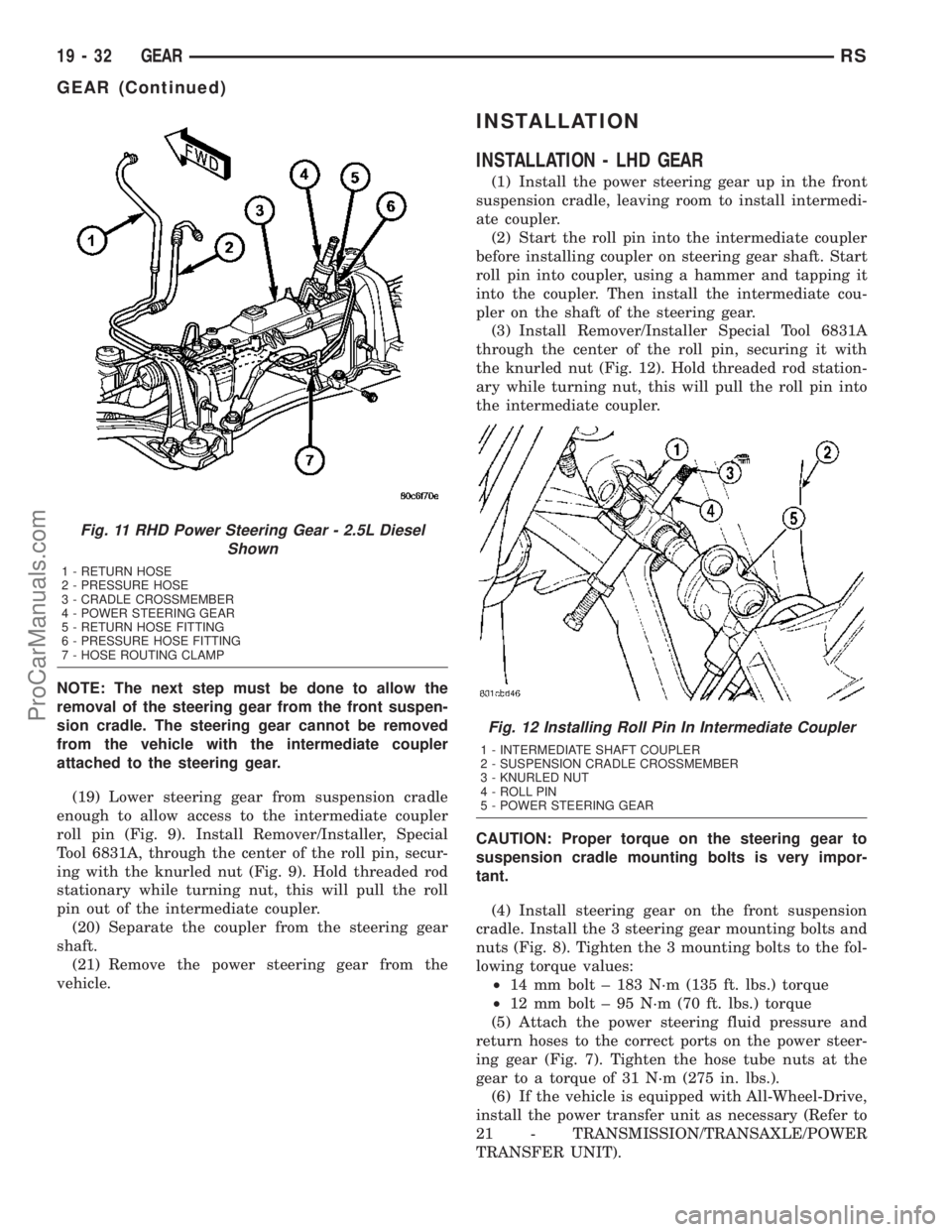
Fig. 11 RHD Power Steering Gear - 2.5L Diesel
Shown
1 - RETURN HOSE
2 - PRESSURE HOSE
3 - CRADLE CROSSMEMBER
4 - POWER STEERING GEAR
5 - RETURN HOSE FITTING
6 - PRESSURE HOSE FITTING
7 - HOSE ROUTING CLAMP
Fig. 12 Installing Roll Pin In Intermediate Coupler
1 - INTERMEDIATE SHAFT COUPLER
2 - SUSPENSION CRADLE CROSSMEMBER
3 - KNURLED NUT
4 - ROLL PIN
5 - POWER STEERING GEAR
19 - 32 GEARRS
GEAR (Continued)
ProCarManuals.com
Page 1428 of 2177
CAUTION: Proper torque on the cradle reinforce-
ment to suspension cradle mounting bolts is very
important.
(7) Install the reinforcement on the front suspen-
sion cradle crossmember and install the bolts attach-
ing the reinforcement to the cradle crossmember
(Fig. 6). Tighten the M-14 size bolts to a torque of
153 N´m (113 ft. lbs.). Tighten the M-12 size bolts to
a torque of 106 N´m (78 ft. lbs.).
(8) Install the lower control arm rear bushing
retainer bolts (M-10 size) through reinforcement on
each side of each lower control arm rear bushing.
Tighten bolts to a torque of 61 N´m (45 ft. lbs.).
(9) Install the two bolts and bushings attaching
the reinforcement and rear of cradle crossmember to
body of vehicle (Fig. 6). Tighten bolts to a torque of
163 N´m (120 ft. lbs.).
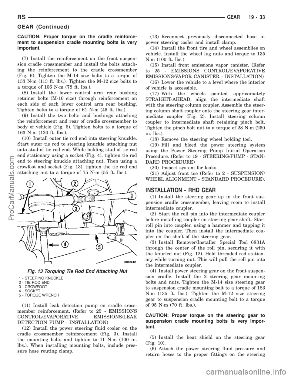
(10) Install outer tie rod end into steering knuckle.
Start outer tie rod to steering knuckle attaching nut
onto stud of tie rod end. While holding stud of tie rod
end stationary using a socket (Fig. 4), tighten tie rod
end to steering knuckle attaching nut. Then using a
crowfoot and socket (Fig. 13), tighten the tie rod end
attaching nut to a torque of 75 N´m (55 ft. lbs.).
(11) Install leak detection pump on cradle cross-
member reinforcement. (Refer to 25 - EMISSIONS
CONTROL/EVAPORATIVE EMISSIONS/LEAK
DETECTION PUMP - INSTALLATION)
(12) Install the power steering fluid cooler on the
cradle crossmember reinforcement (Fig. 3). Install
the mounting bolts and tighten to 11 N´m (100 in.
lbs.). When installing mounting bolts, include pres-
sure hose routing clamp.(13) Reconnect previously disconnected hose at
power steering cooler and install clamp.
(14) Install the front tire and wheel assemblies on
vehicle. Install the wheel lug nuts and torque to 135
N´m (100 ft. lbs.).
(15) Install front emissions vapor canister. (Refer
to 25 - EMISSIONS CONTROL/EVAPORATIVE
EMISSIONS/VAPOR CANISTER - INSTALLATION)
(16) Lower the vehicle to a level where the interior
of vehicle is accessible.
(17) With the wheels pointed approximately
STRAIGHT-AHEAD, align the intermediate shaft
with the steering column coupler. Assemble the steer-
ing column shaft coupler onto the steering gear inter-
mediate coupler (Fig. 2). Install steering column
coupler to intermediate shaft retaining pinch bolt.
Tighten the pinch bolt nut to a torque of 28 N´m (250
in. lbs.).
(18) Remove the steering wheel holding tool.
(19) Fill and bleed the power steering system
using the Power Steering Pump Initial Operation
Procedure. (Refer to 19 - STEERING/PUMP - STAN-
DARD PROCEDURE)
(20) Inspect system for leaks.
(21) Adjust front toe (Refer to 2 - SUSPENSION/
WHEEL ALIGNMENT - STANDARD PROCEDURE).
INSTALLATION - RHD GEAR
(1) Install the steering gear up in the front sus-
pension cradle crossmember, leaving room to install
intermediate coupler.
(2) Start the roll pin into the intermediate coupler
before installing coupler on steering gear shaft. Start
roll pin into coupler, using a hammer and tapping it
into the coupler. Then install the intermediate cou-
pler on the shaft of the steering gear.
(3) Install Remover/Installer Special Tool 6831A
through the center of the roll pin, securing it with
the knurled nut (Fig. 12). Hold threaded rod station-
ary while turning nut. This will pull the roll pin into
the intermediate coupler.
(4) Install power steering gear on the front suspen-
sion cradle. Install the 2 steering gear mounting
bolts and nuts. Tighten the M-14 size steering gear
to suspension cradle mounting bolt to a torque of 183
N´m (135 ft. lbs.). Tighten the M-12 size steering
gear to suspension cradle mounting bolt to a torque
of 95 N´m (70 ft. lbs.).
CAUTION: Proper torque on the steering gear to
suspension cradle mounting bolts is very impor-
tant.
(5) Install the heat shield on the steering gear
(Fig. 10).
(6) Attach the power steering fluid pressure and
return hoses to the proper fittings on the steering
Fig. 13 Torquing Tie Rod End Attaching Nut
1 - STEERING KNUCKLE
2 - TIE ROD END
3 - CROWFOOT
4 - SOCKET
5 - TORQUE WRENCH
RSGEAR19-33
GEAR (Continued)
ProCarManuals.com
Page 1429 of 2177
gear (Fig. 10). Do not fully tighten the fittings at this
time.
(7) Install the routing clamp with the bolt securing
the power steering fluid hoses to the rear of the cra-
dle crossmember (Fig. 11).
(8) Using a crowfoot wrench on a torque wrench,
tighten the power steering fluid hose tube nuts at the
gear to a torque of 31 N´m (275 in. lbs.).
(9) Install tie rod end into steering knuckle. Start
tie rod end to steering knuckle attaching nut onto
stud of tie rod end. While holding stud of tie rod end
stationary using a socket (Fig. 4), tighten tie rod end
to steering knuckle attaching nut. Then using a
crowfoot and socket (Fig. 13), tighten the tie rod end
attaching nut to a torque of 75 N´m (55 ft. lbs.).
(10) If the vehicle is equipped with All-Wheel-
Drive, install the power transfer unit (Refer to 21 -
TRANSMISSION/TRANSAXLE/POWER TRANSFER
UNIT - INSTALLATION).
CAUTION: Proper torque on the cradle reinforce-
ment to suspension cradle mounting bolts is very
important.
(11) Install the reinforcement on the front suspen-
sion cradle crossmember and install the bolts attach-
ing the reinforcement to the cradle crossmember
(Fig. 6). Tighten the M-14 size bolts to a torque of
163 N´m (120 ft. lbs.). Tighten the M-12 size bolts to
a torque of 108 N´m (80 ft. lbs.).
(12) Install the lower control arm rear bushing
retainer bolts through reinforcement on each side of
each lower control arm rear bushing. Tighten bolts to
a torque of 61 N´m (45 ft. lbs.).
(13) Install the two bolts and bushings attaching
the reinforcement and rear of cradle crossmember to
body of vehicle (Fig. 6). Tighten bolts to a torque of
163 N´m (120 ft. lbs.).
(14) If power steering cooler equipped, install the
previously disconnected power steering cooler hose on
the cooler. Install the clamp.
(15) If power steering cooler equipped, install the
power steering fluid cooler on the cradle crossmem-
ber reinforcement (Fig. 3). Install the mounting bolts
and tighten to 11 N´m (100 in. lbs.).
(16) Install the front tire and wheel assemblies on
vehicle. Install the wheel mounting lug nuts and
tighten to a torque to 135 N´m (100 ft. lbs.).
(17) Lower the vehicle to a level were the interior
of vehicle is accessible (keeping tires off the ground).
(18) With the wheels pointed approximately
STRAIGHT-AHEAD, align the intermediate shaft
with the steering column coupler. Assemble the steer-
ing column shaft coupler onto the steering gear inter-
mediate coupler (Fig. 2). Install steering column
coupler to intermediate shaft retaining pinch bolt.Tighten the pinch bolt nut to a torque of 28 N´m (250
in. lbs.).
(19) Remove the steering wheel holding tool.
(20) Perform the POWER STEERING PUMP INI-
TIAL OPERATION procedure to properly fill and
bleed the power steering system. (Refer to 19 -
STEERING/PUMP - STANDARD PROCEDURE)
(21) Inspect for leaks.
(22) Adjust front wheel toe (Refer to 2 - SUSPEN-
SION/WHEEL ALIGNMENT - STANDARD PROCE-
DURE).
SPECIAL TOOLS
POWER STEERING GEAR
OUTER TIE ROD
REMOVAL
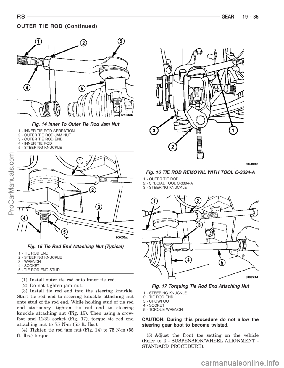
(1) Loosen inner tie rod to outer tie rod jam nut
(Fig. 14).
(2) Remove nut attaching outer tie rod end to
steering knuckle (Fig. 15). The nut is to be removed
from tie rod end by holding tie rod end stud with a
11/32 socket while loosening and removing nut with a
wrench.
(3) Remove the tie rod end stud from steering
knuckle arm, using Remover, Special Tool C-3894±A
(Fig. 16).
(4) Remove outer tie rod end by un-threading it
from the inner tie rod.
INSTALLATION
NOTE: Before installing the outer tie rod, make sure
the jam nut is on inner tie rod (Fig. 14).
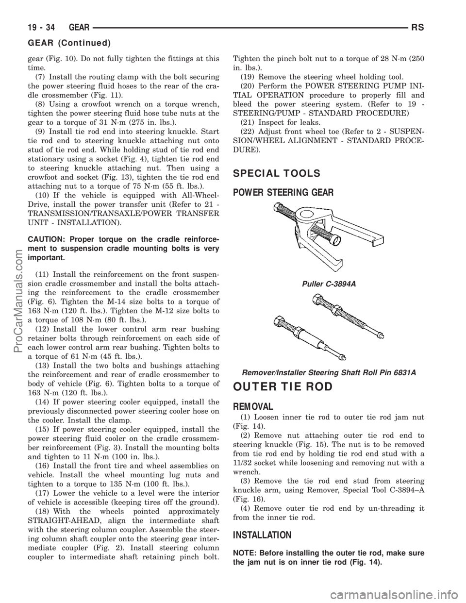
Puller C-3894A
Remover/Installer Steering Shaft Roll Pin 6831A
19 - 34 GEARRS
GEAR (Continued)
ProCarManuals.com
Page 1430 of 2177
(1) Install outer tie rod onto inner tie rod.
(2) Do not tighten jam nut.
(3) Install tie rod end into the steering knuckle.
Start tie rod end to steering knuckle attaching nut
onto stud of tie rod end. While holding stud of tie rod
end stationary, tighten tie rod end to steering
knuckle attaching nut (Fig. 15). Then using a crow-
foot and 11/32 socket (Fig. 17), torque tie rod end
attaching nut to 75 N´m (55 ft. lbs.).
(4) Tighten tie rod jam nut (Fig. 14) to 75 N´m (55
ft. lbs.) torque.CAUTION: During this procedure do not allow the
steering gear boot to become twisted.
(5) Adjust the front toe setting on the vehicle
(Refer to 2 - SUSPENSION/WHEEL ALIGNMENT -
STANDARD PROCEDURE).
Fig. 14 Inner To Outer Tie Rod Jam Nut
1 - INNER TIE ROD SERRATION
2 - OUTER TIE ROD JAM NUT
3 - OUTER TIE ROD END
4 - INNER TIE ROD
5 - STEERING KNUCKLE
Fig. 15 Tie Rod End Attaching Nut (Typical)
1 - TIE ROD END
2 - STEERING KNUCKLE
3 - WRENCH
4 - SOCKET
5 - TIE ROD END STUD
Fig. 16 TIE ROD REMOVAL WITH TOOL C-3894-A
1 - OUTER TIE ROD
2 - SPECIAL TOOL C-3894-A
3 - STEERING KNUCKLE
Fig. 17 Torquing Tie Rod End Attaching Nut
1 - STEERING KNUCKLE
2 - TIE ROD END
3 - CROWFOOT
4 - SOCKET
5 - TORQUE WRENCH
RSGEAR19-35
OUTER TIE ROD (Continued)
ProCarManuals.com
Page 1452 of 2177
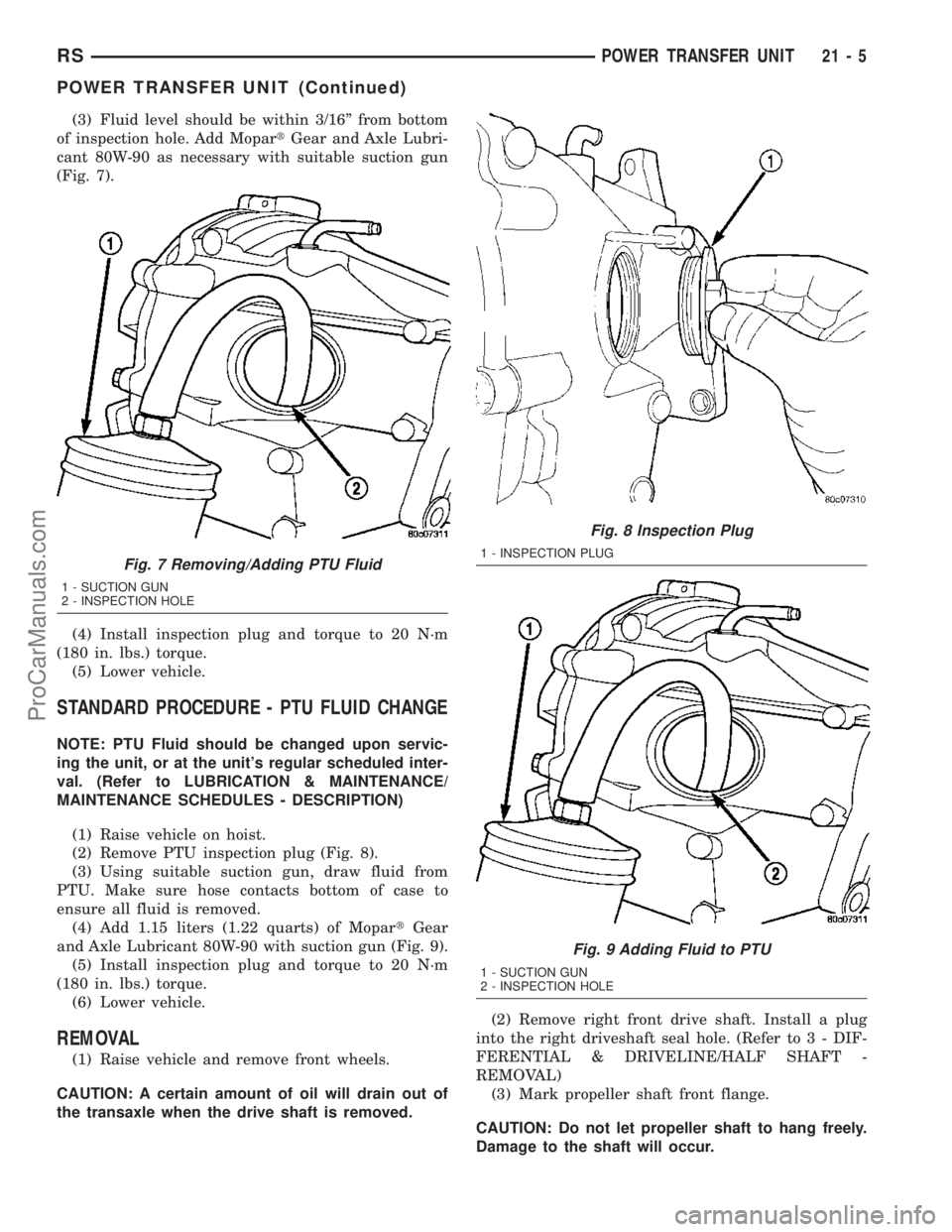
(3) Fluid level should be within 3/16º from bottom
of inspection hole. Add MopartGear and Axle Lubri-
cant 80W-90 as necessary with suitable suction gun
(Fig. 7).
(4) Install inspection plug and torque to 20 N´m
(180 in. lbs.) torque.
(5) Lower vehicle.
STANDARD PROCEDURE - PTU FLUID CHANGE
NOTE: PTU Fluid should be changed upon servic-
ing the unit, or at the unit's regular scheduled inter-
val. (Refer to LUBRICATION & MAINTENANCE/
MAINTENANCE SCHEDULES - DESCRIPTION)
(1) Raise vehicle on hoist.
(2) Remove PTU inspection plug (Fig. 8).
(3) Using suitable suction gun, draw fluid from
PTU. Make sure hose contacts bottom of case to
ensure all fluid is removed.
(4) Add 1.15 liters (1.22 quarts) of MopartGear
and Axle Lubricant 80W-90 with suction gun (Fig. 9).
(5) Install inspection plug and torque to 20 N´m
(180 in. lbs.) torque.
(6) Lower vehicle.
REMOVAL
(1) Raise vehicle and remove front wheels.
CAUTION: A certain amount of oil will drain out of
the transaxle when the drive shaft is removed.(2) Remove right front drive shaft. Install a plug
into the right driveshaft seal hole. (Refer to 3 - DIF-
FERENTIAL & DRIVELINE/HALF SHAFT -
REMOVAL)
(3) Mark propeller shaft front flange.
CAUTION: Do not let propeller shaft to hang freely.
Damage to the shaft will occur.
Fig. 7 Removing/Adding PTU Fluid
1 - SUCTION GUN
2 - INSPECTION HOLE
Fig. 8 Inspection Plug
1 - INSPECTION PLUG
Fig. 9 Adding Fluid to PTU
1 - SUCTION GUN
2 - INSPECTION HOLE
RSPOWER TRANSFER UNIT21-5
POWER TRANSFER UNIT (Continued)
ProCarManuals.com
Page 1498 of 2177
INSTALLATION
INSTALLATION - 2.4L GAS
(1) Install modular clutch assembly to transaxle.
Assemble transaxle to engine.
(2) Install and torque transaxle-to-engine bolts to
95 N´m (70 ft. lbs.).
(3) Raise transaxle/engine assembly into position
and install upper mount through-bolt. Torque
through-bolt to 75 N´m (55 ft. lbs.).
(4) Remove screw jack.
(5) Install and torque modular clutch assembly-to-
drive plate bolts to 88 N´m (65 ft. lbs.)
(6) Install structural collar.
(7) Connect back-up lamp switch connector.
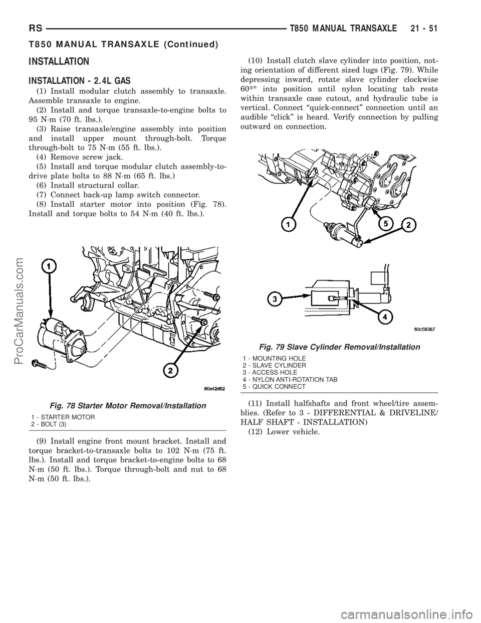
(8) Install starter motor into position (Fig. 78).
Install and torque bolts to 54 N´m (40 ft. lbs.).
(9) Install engine front mount bracket. Install and
torque bracket-to-transaxle bolts to 102 N´m (75 ft.
lbs.). Install and torque bracket-to-engine bolts to 68
N´m (50 ft. lbs.). Torque through-bolt and nut to 68
N´m (50 ft. lbs.).(10) Install clutch slave cylinder into position, not-
ing orientation of different sized lugs (Fig. 79). While
depressing inward, rotate slave cylinder clockwise
60tÉ into position until nylon locating tab rests
within transaxle case cutout, and hydraulic tube is
vertical. Connect ªquick-connectº connection until an
audible ªclickº is heard. Verify connection by pulling
outward on connection.
(11) Install halfshafts and front wheel/tire assem-
blies. (Refer to 3 - DIFFERENTIAL & DRIVELINE/
HALF SHAFT - INSTALLATION)
(12) Lower vehicle.
Fig. 78 Starter Motor Removal/Installation
1 - STARTER MOTOR
2 - BOLT (3)
Fig. 79 Slave Cylinder Removal/Installation
1 - MOUNTING HOLE
2 - SLAVE CYLINDER
3 - ACCESS HOLE
4 - NYLON ANTI-ROTATION TAB
5 - QUICK CONNECT
RST850 MANUAL TRANSAXLE21-51
T850 MANUAL TRANSAXLE (Continued)
ProCarManuals.com
Page 1501 of 2177
(8) Install engine front mount bracket. Install and
torque bracket-to-transaxle bolts to 102 N´m (75 ft.
lbs.). Install and torque bracket-to-engine bolts to 68
N´m (50 ft. lbs.). Torque through-bolt and nut to 68
N´m (50 ft. lbs.).
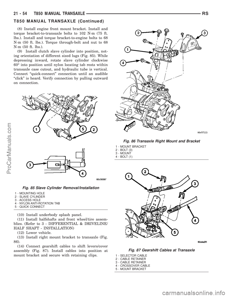
(9) Install clutch slave cylinder into position, not-
ing orientation of different sized lugs (Fig. 85). While
depressing inward, rotate slave cylinder clockwise
60É into position until nylon locating tab rests within
transaxle case cutout, and hydraulic tube is vertical.
Connect ªquick-connectº connection until an audible
ªclickº is heard. Verify connection by pulling outward
on connection.
(10) Install underbody splash panel.
(11) Install halfshafts and front wheel/tire assem-
blies. (Refer to 3 - DIFFERENTIAL & DRIVELINE/
HALF SHAFT - INSTALLATION)
(12) Lower vehicle.
(13) Install right mount bracket to transaxle (Fig.
86).
(14) Connect gearshift cables to shift levers/cover
assembly (Fig. 87). Install cables into position at
mount bracket and secure with retaining clips.
Fig. 85 Slave Cylinder Removal/Installation
1 - MOUNTING HOLE
2 - SLAVE CYLINDER
3 - ACCESS HOLE
4 - NYLON ANTI-ROTATION TAB
5 - QUICK CONNECT
Fig. 86 Transaxle Right Mount and Bracket
1 - MOUNT BRACKET
2 - BOLT (3)
3 - MOUNT
4 - BOLT (1)
Fig. 87 Gearshift Cables at Transaxle
1 - SELECTOR CABLE
2 - CABLE RETAINER
3 - CABLE RETAINER
4 - CROSSOVER CABLE
5 - MOUNT BRACKET
21 - 54 T850 MANUAL TRANSAXLERS
T850 MANUAL TRANSAXLE (Continued)
ProCarManuals.com
Page 1509 of 2177

BACK-UP LAMP SWITCH
REMOVAL
(1) Raise vehicle on hoist.
(2) Disconnect back-up lamp switch connector.
(3) Remove back-up lamp switch (Fig. 95).
INSTALLATION
(1) Install back-up lamp switch (Fig. 95) and
torque to 23 N´m (17 ft. lbs.) using Tool 8827.
(2) Connect back-up lamp switch connector.
(3) Lower vehicle.
DIFFERENTIAL
DESCRIPTION
The T850 differential is a conventional open design.
It consists of a ring gear and a two-piece differential
case. The differential case contains the pinion and side
gears, three floating pinion shafts, and a pinion shaft
retaining ring (Fig. 96). The differential case is sup-
ported in the transaxle by tapered roller bearings.
OPERATION
The differential assembly is driven by the interme-
diate shaft via the ring gear. The ring gear drives the
differential case, and the case drives the halfshafts
through the differential gears. The differential pinion
and side gears are supported in the case by pinion
shafts and thrust washers. Differential pinion and
side gears make it possible for front wheels to rotate
at different speeds while cornering.
DISASSEMBLY
(1) Remove differential side bearings:
(a) Install button 8491-1 to differential case (Fig.
97).(b) Set up Tool 5048 (5048-1, -4, -6) as shown in
(Fig. 98).
(c) Remove differential side bearing (Fig. 99).
Same procedure/tools work for both sides.
Fig. 95 Back-Up Lamp Switch
1 - BACK-UP LAMP SWITCH
Fig. 96 Differential Assembly
1 - RING GEAR
2 - SUPPORT PLATE
3 - SIDE GEAR (2)
4 - PINION GEAR (4)
5 - BOLT (12)
6 - PINION SHAFT (2-SHORT)
7 - PINION SHAFT (1-LONG)
8 - THRUST WASHER (2)
9 - RETAINING RING
10 - DIFFERENTIAL CASE
Fig. 97 Tool 8491
1 - TOOL 8491
21 - 62 T850 MANUAL TRANSAXLERS
ProCarManuals.com