2003 CHRYSLER CARAVAN window
[x] Cancel search: windowPage 2086 of 2177
(4) Open both the suction and discharge valves,
then open the charge valve to allow the heated
refrigerant to flow into the system.
(5) When the transfer of refrigerant has stopped,
close both the suction and discharge valves.
(6) If all of the refrigerant charge did not transfer
from the dispensing device, open all of the windows
in the vehicle and set the heater-air conditioner con-
trols so that the compressor is engaged and the
blower motor is operating at its lowest speed setting.
Run the engine at a steady high idle (about 1400
rpm). If the compressor will not engage, test the com-
pressor clutch control circuit and repair as required.
(7) Open the suction valve to allow the remaining
refrigerant to transfer to the refrigerant system.
WARNING: TAKE CARE NOT TO OPEN THE DIS-
CHARGE (HIGH PRESSURE) VALVE AT THIS TIME.
(8) Close the suction valve and test the system
performance. (Refer to 24 - HEATING & AIR CON-
DITIONING - STANDARD PROCEDURE - A/C PER-
FORMANCE TEST).
(9) Disconnect the charging station and manifold
gauge set from the refrigerant system service ports.
(10) Reinstall the caps onto the refrigerant system
service ports.
(11) Run the HVAC Control Cooldown test to ver-
ify proper operation(Refer to 24 - HEATING & AIR
CONDITIONING - DIAGNOSIS AND TESTING).
STANDARD PROCEDURE - REFRIGERANT
SYSTEM EVACUATE
WARNING: REFER TO THE APPLICABLE WARN-
INGS AND CAUTIONS FOR THIS SYSTEM BEFORE
PERFORMING THE FOLLOWING OPERATION.
(Refer to 24 - HEATING & AIR CONDITIONING/
PLUMBING - FRONT - WARNING - A/C PLUMBING)
and (Refer to 24 - HEATING & AIR CONDITIONING/
PLUMBING - FRONT - CAUTION - A/C PLUMBING).
If the refrigerant system has been open to the
atmosphere, it must be evacuated before the system
can be charged. If moisture and air enters the system
and becomes mixed with the refrigerant, the com-
pressor head pressure will rise above acceptable
operating levels. This will reduce the performance of
the air conditioner and damage the compressor.
Evacuating the refrigerant system will remove the
air and boil the moisture out of the system at near
room temperature. A R-134a refrigerant recovery/re-
cycling/charging station that meets SAE Standard
J2210 must be used to evacuate the refrigerant sys-
tem. See the operating instructions supplied by the
equipment manufacturer for proper care and use ofthis equipment. To evacuate the refrigerant system,
use the following procedure:
NOTE: When connecting the service equipment
couplings to the refrigerant system service ports,
be certain that the valve of each coupling is fully
closed. This will reduce the amount of effort
required to make the connection.
(1) Remove the caps from the refrigerant system
service ports and attach a manifold gauge set and a
R-134a refrigerant recovery/recycling/charging sta-
tion that meets SAE Standard J2210 to the refriger-
ant system.
(2) Open both the suction and discharge valves
and start the charging station vacuum pump.
(3) When the suction gauge has read 88 kPa (26
in. Hg.) vacuum or greater for 45 minutes, close both
the suction and discharge valves and turn off the
vacuum pump. If the refrigerant system fails to
reach the specified vacuum, the system has a leak
that must be corrected. (Refer to 24 - HEATING &
AIR CONDITIONING/PLUMBING - FRONT/RE-
FRIGERANT - STANDARD PROCEDURE -
REFRIGERANT SYSTEM LEAKS).
(4) If the refrigerant system maintains the speci-
fied vacuum for thirty minutes, restart the vacuum
pump, open both the suction and discharge valves,
and evacuate the system for an additional ten min-
utes.
(5) Close both the suction and discharge valves,
and turn off the charging station vacuum pump.
(6) The refrigerant system is now ready to be
charged with R-134a refrigerant. (Refer to 24 -
HEATING & AIR CONDITIONING/PLUMBING -
FRONT/REFRIGERANT - STANDARD PROCE-
DURE - REFRIGERANT SYSTEM CHARGE).
STANDARD PROCEDURE - REFRIGERANT
RECOVERY
WARNING: REFER TO THE APPLICABLE WARN-
INGS AND CAUTIONS FOR THIS SYSTEM BEFORE
PERFORMING THE FOLLOWING OPERATION.
(Refer to 24 - HEATING & AIR CONDITIONING/
PLUMBING - FRONT - WARNING - A/C PLUMBING)
and (Refer to 24 - HEATING & AIR CONDITIONING/
PLUMBING - FRONT - CAUTION - A/C PLUMBING).
A R-134a refrigerant recovery/recycling/charging
station that meets SAE Standard J2210 must be
used to recover the refrigerant from an R-134a refrig-
erant system, whenever the refrigerant system must
be opened for service. See the operating instructions
supplied by the equipment manufacturer for the
proper care and use of this equipment.
RSPLUMBING - FRONT24-89
REFRIGERANT (Continued)
ProCarManuals.com
Page 2094 of 2177

OPERATION
A mechanical sensor in the expansion valve control
head monitors the temperature and pressure of the
refrigerant leaving the evaporator coil through the
suction line, and adjusts the orifice size at the liquid
line to let the proper amount of refrigerant into the
evaporator coil to meet the vehicle cooling require-
ments. Controlling the refrigerant flow through the
evaporator ensures that none of the refrigerant leav-
ing the evaporator is still in a liquid state, which
could damage the compressor.
DIAGNOSIS AND TESTING - EXPANSION VALVE
WARNING: REFER TO THE APPLICABLE WARN-
INGS AND CAUTIONS FOR THIS SYSTEM BEFORE
PERFORMING THE FOLLOWING OPERATION.
(Refer to 24 - HEATING & AIR CONDITIONING/
PLUMBING - FRONT - WARNING - A/C PLUMBING)
and (Refer to 24 - HEATING & AIR CONDITIONING/
PLUMBING - FRONT - CAUTION - A/C PLUMBING).
NOTE: The expansion valve should only be tested
following testing of the compressor.
NOTE: Liquid CO
2is required to test the expansion
valve. This material is available from most welding
supply facilities. Liquid CO
2is also available from
companies which service and sell fire extinguish-
ers.
When testing the expansion valve, the work area
and the vehicle temperature must be 21É to 27É C
(70É to 85É F). To test the expansion valve:
(1) Connect a charging station or manifold gauge
set to the refrigerant system service ports. Verify the
refrigerant charge level.
(2) Close all doors, windows and vents to the pas-
senger compartment.
(3) Set the heater-air conditioner controls so that
the compressor is operating, the temperature control
is in the highest temperature position, the mode door
is directing the output to the floor outlets, and the
blower is operating at the highest speed setting.
(4) Start the engine and allow it to idle at 1000
rpm. After the engine has reached normal operating
temperature, allow the passenger compartment to
heat up. This will create the need for maximum
refrigerant flow into the evaporator.
(5) If the refrigerant charge is sufficient, the dis-
charge (high pressure) gauge should read 965 to 1655
kPa (140 to 240 psi). The suction (low pressure)
gauge should read 140 kPa to 207 kPa (20 psi to 30
psi). If OK, go to Step 6. If not OK, replace the faulty
expansion valve.WARNING: PROTECT THE SKIN AND EYES FROM
EXPOSURE TO LIQUID CO
2. PERSONAL INJURY
CAN RESULT.
(6) If the suction (low pressure) gauge reads
within the specified range, freeze the expansion valve
control head for 30 seconds using liquid CO
2or
another suitable super-cold material.Do not spray
R-134a or R-12 refrigerant on the expansion
valve control head for this test.The suction (low
pressure) gauge reading should drop by 10 psi. If OK,
go to Step 7 If not OK, replace the faulty expansion
valve.
(7) Allow the expansion valve control head to thaw.
The suction (low pressure) gauge reading should sta-
bilize at 140 kPa to 240 kPa (20 psi to 30 psi). If not
OK, replace the faulty expansion valve.
(8) When expansion valve testing is complete, test
the overall air conditioner performance. (Refer to 24 -
HEATING & AIR CONDITIONING - DIAGNOSIS
AND TESTING - A/C PERFORMANCE TEST).
Remove all test equipment before returning the vehi-
cle to service.
REMOVAL
WARNING: REFER TO THE APPLICABLE WARN-
INGS AND CAUTIONS FOR THIS SYSTEM BEFORE
PERFORMING THE FOLLOWING OPERATION.
(Refer to 24 - HEATING & AIR CONDITIONING/
PLUMBING - FRONT - WARNING - A/C PLUMBING),
(Refer to 24 - HEATING & AIR CONDITIONING/
PLUMBING - FRONT - CAUTION - A/C PLUMBING),
and (Refer to 24 - HEATING & AIR CONDITIONING/
PLUMBING - FRONT - WARNING - HEATER PLUMB-
ING).
(1) Remove the rear heater-A/C unit housing from
the vehicle. (Refer to 24 - HEATING & AIR CONDI-
TIONING/DISTRIBUTION - REAR/REAR HEATER-
A/C HOUSING - REMOVAL).
(2) Carefully remove the foam insulator wrap from
the rear expansion valve.
(3) Remove the rear evaporator line extension from
the expansion valve. (Refer to 24 - HEATING & AIR
CONDITIONING/PLUMBING - REAR/EVAPORA-
TOR - REMOVAL - EVAPORATOR LINE EXTEN-
SION).
(4) Remove the two screws that secure the expan-
sion valve to the evaporator tube sealing plate.
(5) Remove the expansion valve from the evapora-
tor tubes.
(6) Remove the seals from the evaporator tube fit-
tings and discard.
(7) Install plugs in, or tape over the opened evap-
orator tube fittings and both expansion valve ports.
RSPLUMBING - REAR24-97
EXPANSION VALVE (Continued)
ProCarManuals.com
Page 2135 of 2177
ON-BOARD DIAGNOSTICS
TABLE OF CONTENTS
page page
TASK MANAGER
DESCRIPTION.........................24OPERATION...........................24
TASK MANAGER
DESCRIPTION
The PCM is responsible for efficiently coordinating
the operation of all the emissions-related compo-
nents. The PCM is also responsible for determining if
the diagnostic systems are operating properly. The
software designed to carry out these responsibilities
is call the ªTask Managerº.
OPERATION
The Task Manager determines when tests happen
and when functions occur. Many of the diagnostic
steps required by OBD II must be performed under
specific operating conditions. The Task Manager soft-
ware organizes and prioritizes the diagnostic proce-
dures. The job of the Task Manager is to determine if
conditions are appropriate for tests to be run, moni-
tor the parameters for a trip for each test, and record
the results of the test. Following are the responsibil-
ities of the Task Manager software:
²Test Sequence
²MIL Illumination
²Diagnostic Trouble Codes (DTCs)
²Trip Indicator
²Freeze Frame Data Storage
²Similar Conditions Window
Test Sequence
In many instances, emissions systems must fail
diagnostic tests more than once before the PCM illu-
minates the MIL. These tests are known as 'two trip
monitors.' Other tests that turn the MIL lamp on
after a single failure are known as 'one trip moni-
tors.' A trip is defined as 'start the vehicle and oper-
ate it to meet the criteria necessary to run the given
monitor.'
Many of the diagnostic tests must be performed
under certain operating conditions. However, there
are times when tests cannot be run because another
test is in progress (conflict), another test has failed
(pending) or the Task Manager has set a fault that
may cause a failure of the test (suspend).
²Pending
Under some situations the Task Manager will notrun a monitor if the MIL is illuminated and a fault is
stored from another monitor. In these situations, the
Task Manager postpones monitorspendingresolu-
tion of the original fault. The Task Manager does not
run the test until the problem is remedied.
For example, when the MIL is illuminated for an
Oxygen Sensor fault, the Task Manager does not run
the Catalyst Monitor until the Oxygen Sensor fault is
remedied. Since the Catalyst Monitor is based on sig-
nals from the Oxygen Sensor, running the test would
produce inaccurate results.
²Conflict
There are situations when the Task Manager does
not run a test if another monitor is in progress. In
these situations, the effects of another monitor run-
ning could result in an erroneous failure. If thiscon-
flictis present, the monitor is not run until the
conflicting condition passes. Most likely the monitor
will run later after the conflicting monitor has
passed.
For example, if the Fuel System Monitor is in
progress, the Task Manager does not run the catalyst
Monitor. Since both tests monitor changes in air/fuel
ratio and adaptive fuel compensation, the monitors
will conflict with each other.
²Suspend
Occasionally the Task Manager may not allow a two
trip fault to mature. The Task Manager willsus-
pendthe maturing of a fault if a condition exists
that may induce an erroneous failure. This prevents
illuminating the MIL for the wrong fault and allows
more precise diagnosis.
For example, if the PCM is storing a one trip fault
for the Oxygen Sensor and the catalyst monitor, the
Task Manager may still run the catalyst Monitor but
will suspend the results until the Oxygen Sensor
Monitor either passes or fails. At that point the Task
Manager can determine if the catalyst system is
actually failing or if an Oxygen Sensor is failing.
MIL Illumination
The PCM Task Manager carries out the illumina-
tion of the MIL. The Task Manager triggers MIL illu-
mination upon test failure, depending on monitor
failure criteria.
25 - 24 ON-BOARD DIAGNOSTICSRS
ProCarManuals.com
Page 2136 of 2177
The Task Manager Screen shows both a Requested
MIL state and an Actual MIL state. When the MIL is
illuminated upon completion of a test for a good trip,
the Requested MIL state changes to OFF. However,
the MIL remains illuminated until the next key
cycle. (On some vehicles, the MIL will actually turn
OFF during the thirdgood trip) During the key cycle
for the third good trip, the Requested MIL state is
OFF, while the Actual MIL state is ON. After the
next key cycle, the MIL is not illuminated and both
MIL states read OFF.
Diagnostic Trouble Codes (DTCs)
With OBD II, different DTC faults have different
priorities according to regulations. As a result, the
priorities determine MIL illumination and DTC era-
sure. DTCs are entered according to individual prior-
ity. DTCs with a higher priority overwrite lower
priority DTCs.
Priorities
²Priority 0 ÐNon-emissions related trouble codes.
²Priority 1 Ð One trip failure of a two trip fault
for non-fuel system and non-misfire. (MIL Off)
²Priority 2 Ð One trip failure of a two trip fault
for fuel system (rich/lean) or misfire. (MIL Off)
²Priority3ÐTwotrip failure for a non-fuel sys-
tem and non-misfire or matured one trip comprehen-
sive component fault. (MIL On)
²Priority4ÐTwotrip failure or matured fault
for fuel system (rich/lean) and misfire or one trip cat-
alyst damaging misfire. Catalyst damage misfire is a
2 trip MIL. The MIL flashes on the first trip when
catalyst damage misfire levels are present. (MIL On)
Non-emissions related failures have no priority.
One trip failures of two trip faults have low priority.
Two trip failures or matured faults have higher pri-
ority. One and two trip failures of fuel system and
misfire monitor take precedence over non-fuel system
and non-misfire failures.
DTC Self Erasure
With one trip components or systems, the MIL is
illuminated upon test failure and DTCs are stored.
Two trip monitors are components requiring failure
in two consecutive trips for MIL illumination. Upon
failure of the first test, the Task Manager enters a
maturing code. If the component fails the test for a
second time the code matures and a DTC is set.
After three good trips the MIL is extinguished and
the Task Manager automatically switches the trip
counter to a warm-up cycle counter. DTCs are auto-
matically erased following 40 warm-up cycles if the
component does not fail again.
For misfire and fuel system monitors, the compo-
nent must pass the test under a Similar Conditions
Window in order to record a good trip. A Similar Con-ditions Window is when engine RPM is within 375
RPM and load is within 20% of when the fault
occurred.
NOTE: It is important to understand that a compo-
nent does not have to fail under a similar window of
operation to mature. It must pass the test under a
Similar Conditions Window when it failed to record
a Good Trip for DTC erasure for misfire and fuel
system monitors.
DTCs can be erased anytime with a DRBIIIt.
Erasing the DTC with the DRBIIIterases all OBD II
information. The DRBIIItautomatically displays a
warning that erasing the DTC will also erase all
OBD II monitor data. This includes all counter infor-
mation for warm-up cycles, trips and Freeze Frame.
Trip Indicator
TheTripis essential for running monitors and
extinguishing the MIL. In OBD II terms, a trip is a
set of vehicle operating conditions that must be met
for a specific monitor to run. All trips begin with a
key cycle.
Good Trip
The Good Trip counters are as follows:
²Global Good Trip
²Fuel System Good Trip
²Misfire Good Trip
²Alternate Good Trip (appears as a Global Good
Trip on DRBIIIt)
²Comprehensive Components
²Major Monitor
²Warm-Up Cycles
Global Good Trip
To increment a Global Good Trip, the Oxygen sen-
sor and Catalyst efficiency monitors must have run
and passed, and 2 minutes of engine run time.
Fuel System Good Trip
To count a good trip (three required) and turn off
the MIL, the following conditions must occur:
²Engine in closed loop
²Operating in Similar Conditions Window
²Short Term multiplied by Long Term less than
threshold
²Less than threshold for a predetermined time
If all of the previous criteria are met, the PCM will
count a good trip (three required) and turn off the
MIL.
Misfire Good Trip
If the following conditions are met the PCM will
count one good trip (three required) in order to turn
off the MIL:
²Operating in Similar Condition Window
²1000 engine revolutions with no misfire
RSON-BOARD DIAGNOSTICS25-25
TASK MANAGER (Continued)
ProCarManuals.com
Page 2137 of 2177
Alternate Good Trip
Alternate Good Trips are used in place of Global
Good Trips for Comprehensive Components and
Major Monitors. If the Task Manager cannot run a
Global Good Trip because a component fault is stop-
ping the monitor from running, it will attempt to
count an Alternate Good Trip.
The Task Manager counts an Alternate Good Trip
for Comprehensive components when the following
conditions are met:
²Two minutes of engine run time, idle or driving
²No other faults occur
The Task Manager counts an Alternate Good Trip
for a Major Monitor when the monitor runs and
passes. Only the Major Monitor that failed needs to
pass to count an Alternate Good Trip.
Warm-Up Cycles
Once the MIL has been extinguished by the Good
Trip Counter, the PCM automatically switches to a
Warm-Up Cycle Counter that can be viewed on the
DRBIIIt. Warm-Up Cycles are used to erase DTCs
and Freeze Frames. Forty Warm-Up cycles must
occur in order for the PCM to self-erase a DTC and
Freeze Frame. A Warm-Up Cycle is defined as fol-
lows:
²Engine coolant temperature must start below
and rise above 160É F
²Engine coolant temperature must rise by 40É F
²No further faults occur
Freeze Frame Data Storage
Once a failure occurs, the Task Manager records
several engine operating conditions and stores it in a
Freeze Frame. The Freeze Frame is considered one
frame of information taken by an on-board data
recorder. When a fault occurs, the PCM stores the
input data from various sensors so that technicians
can determine under what vehicle operating condi-
tions the failure occurred.
The data stored in Freeze Frame is usually
recorded when a system fails the first time for two
trip faults. Freeze Frame data will only be overwrit-
ten by a different fault with a higher priority.
CAUTION: Erasing DTCs, either with the DRBIIIT;or
by disconnecting the battery, also clears all Freeze
Frame data.
Similar Conditions Window
The Similar Conditions Window displays informa-
tion about engine operation during a monitor. Abso-
lute MAP (engine load) and Engine RPM are stored
in this window when a failure occurs. There are two
different Similar conditions Windows: Fuel System
and Misfire.FUEL SYSTEM
²Fuel System Similar Conditions WindowÐ
An indicator that 'Absolute MAP When Fuel Sys Fail'
and 'RPM When Fuel Sys Failed' are all in the same
range when the failure occurred. Indicated by switch-
ing from 'NO' to 'YES'.
²Absolute MAP When Fuel Sys FailÐ The
stored MAP reading at the time of failure. Informs
the user at what engine load the failure occurred.
²Absolute MAPÐ A live reading of engine load
to aid the user in accessing the Similar Conditions
Window.
²RPM When Fuel Sys FailÐ The stored RPM
reading at the time of failure. Informs the user at
what engine RPM the failure occurred.
²Engine RPMÐ A live reading of engine RPM
to aid the user in accessing the Similar Conditions
Window.
²Adaptive Memory FactorÐ The PCM utilizes
both Short Term Compensation and Long Term Adap-
tive to calculate the Adaptive Memory Factor for
total fuel correction.
²Upstream O2S VoltsÐ A live reading of the
Oxygen Sensor to indicate its performance. For
example, stuck lean, stuck rich, etc.
²SCW Time in Window (Similar Conditions
Window Time in Window)Ð A timer used by the
PCM that indicates that, after all Similar Conditions
have been met, if there has been enough good engine
running time in the SCW without failure detected.
This timer is used to increment a Good Trip.
²Fuel System Good Trip CounterÐATrip
Counter used to turn OFF the MIL for Fuel System
DTCs. To increment a Fuel System Good Trip, the
engine must be in the Similar Conditions Window,
Adaptive Memory Factor must be less than cali-
brated threshold and the Adaptive Memory Factor
must stay below that threshold for a calibrated
amount of time.
²Test Done This TripÐ Indicates that the
monitor has already been run and completed during
the current trip.
MISFIRE
²Same Misfire Warm-Up StateÐ Indicates if
the misfire occurred when the engine was warmed up
(above 160É F).
²In Similar Misfire WindowÐ An indicator
that 'Absolute MAP When Misfire Occurred' and
'RPM When Misfire Occurred' are all in the same
range when the failure occurred. Indicated by switch-
ing from 'NO' to 'YES'.
²Absolute MAP When Misfire OccurredÐ
The stored MAP reading at the time of failure.
Informs the user at what engine load the failure
occurred.
25 - 26 ON-BOARD DIAGNOSTICSRS
TASK MANAGER (Continued)
ProCarManuals.com
Page 2138 of 2177
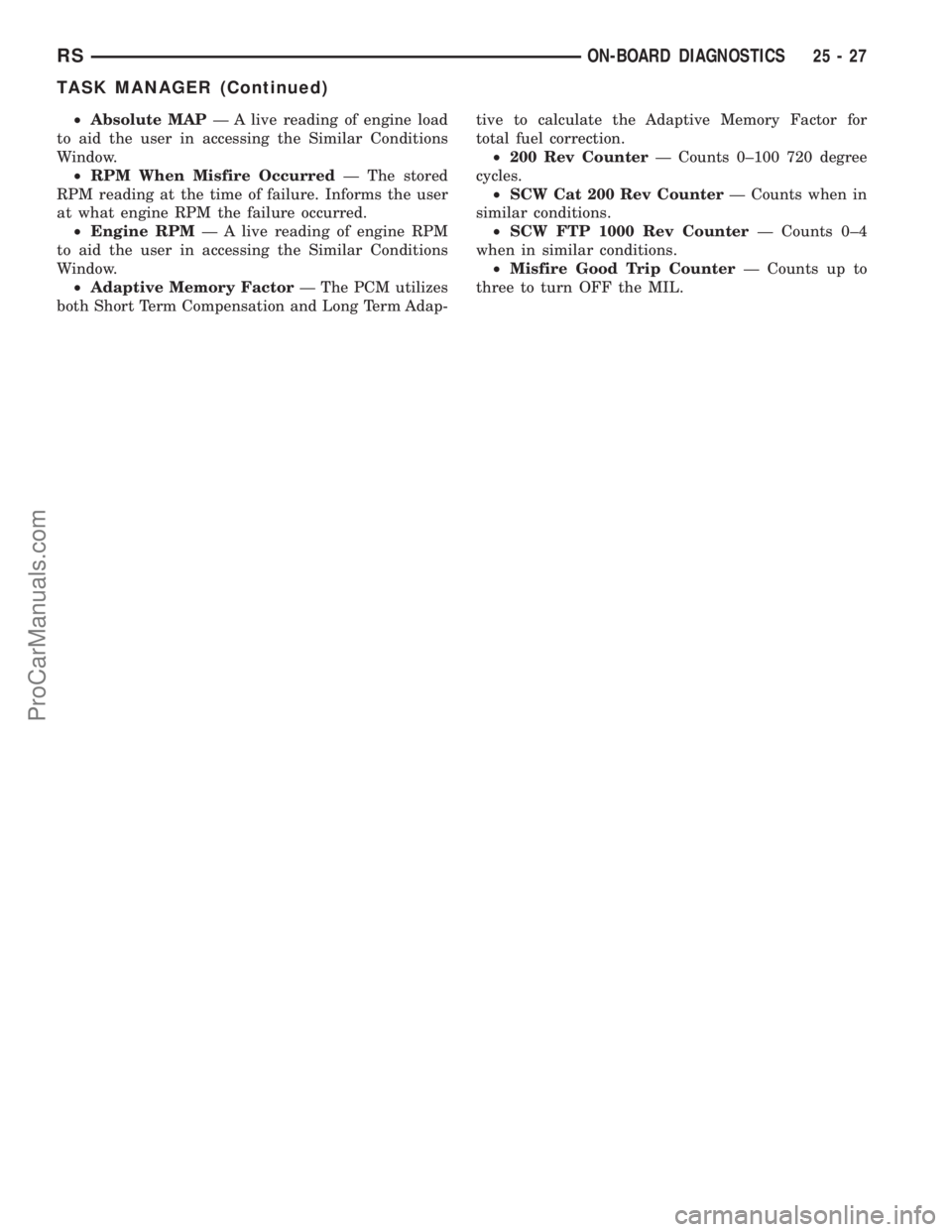
²Absolute MAPÐ A live reading of engine load
to aid the user in accessing the Similar Conditions
Window.
²RPM When Misfire OccurredÐ The stored
RPM reading at the time of failure. Informs the user
at what engine RPM the failure occurred.
²Engine RPMÐ A live reading of engine RPM
to aid the user in accessing the Similar Conditions
Window.
²Adaptive Memory FactorÐ The PCM utilizes
both Short Term Compensation and Long Term Adap-tive to calculate the Adaptive Memory Factor for
total fuel correction.
²200 Rev CounterÐ Counts 0±100 720 degree
cycles.
²SCW Cat 200 Rev CounterÐ Counts when in
similar conditions.
²SCW FTP 1000 Rev CounterÐ Counts 0±4
when in similar conditions.
²Misfire Good Trip CounterÐ Counts up to
three to turn OFF the MIL.
RSON-BOARD DIAGNOSTICS25-27
TASK MANAGER (Continued)
ProCarManuals.com
Page 2147 of 2177
COOLANT LEVEL CHECK - STANDARD
PROCEDURE..........................7-5
COOLANT RECOVERY CONTAINER -
DESCRIPTION........................7-19
COOLANT RECOVERY CONTAINER -
INSTALLATION........................7-20
COOLANT RECOVERY CONTAINER -
OPERATION..........................7-19
COOLANT RECOVERY CONTAINER -
REMOVAL...........................7-20
COOLANT RECOVERY SYSTEM -
DIAGNOSIS AND TESTING..............7-20
COOLANT SERVICE - STANDARD
PROCEDURE.........................7-19
COOLANT TEMPERATURE SENSOR -
2.4L - DESCRIPTION, ENGINE............7-21
COOLANT TEMPERATURE SENSOR -
2.4L - INSTALLATION, ENGINE...........7-21
COOLANT TEMPERATURE SENSOR -
2.4L - REMOVAL, ENGINE...............7-21
COOLANT TEMPERATURE SENSOR -
3.3/3.8L - DESCRIPTION, ENGINE.........7-21
COOLANT TEMPERATURE SENSOR -
3.3/3.8L - INSTALLATION, ENGINE........7-22
COOLANT TEMPERATURE SENSOR -
3.3/3.8L - REMOVAL, ENGINE............7-21
COOLANT THERMOSTAT - 2.4L -
INSTALLATION, ENGINE................7-23
COOLANT THERMOSTAT - 2.4L -
REMOVAL, ENGINE....................7-23
COOLANT THERMOSTAT - 3.3/3.8L -
INSTALLATION, ENGINE................7-24
COOLANT THERMOSTAT - 3.3/3.8L -
REMOVAL, ENGINE......................7-23
COOLANT THERMOSTAT - DESCRIPTION,
ENGINE.............................7-22
COOLANT THERMOSTAT - DIAGNOSIS
AND TESTING, ENGINE.................7-23
COOLANT THERMOSTAT - OPERATION,
ENGINE.............................7-22
COOLER - DESCRIPTION, FLUID.........19-44
COOLER - DESCRIPTION,
TRANSMISSION OIL...................7-37
COOLER - INSPECTION, TRANSMISSION
OIL ................................7-37
COOLER - INSTALLATION, FLUID........19-45
COOLER - INSTALLATION,
TRANSMISSION OIL...................7-37
COOLER & LINES - DESCRIPTION, OIL . . . 9-138
COOLER & LINES - INSTALLATION, OIL . . . 9-138
COOLER & LINES - OPERATION, OIL.....9-138
COOLER & LINES - REMOVAL, OIL.......9-138
COOLER - OPERATION, FLUID..........19-44
COOLER - REMOVAL, FLUID............19-44
COOLER - REMOVAL, TRANSMISSION
OIL ................................7-37
COOLER LINES - INSTALLATION,
TRANSMISSION OIL...................7-38
COOLER LINES - REMOVAL,
TRANSMISSION OIL...................7-38
COOLING SYSTEM - DESCRIPTION........7-1
COOLING SYSTEM - DIAGNOSIS AND
TESTING, ENGINE.....................7-14
COOLING SYSTEM - OPERATION..........7-2
COOLING SYSTEM AERATION -
DIAGNOSIS AND TESTING...............7-3
COOLING SYSTEM DEAERATION -
DIAGNOSIS AND TESTING
...............7-4
COOLING SYSTEM DRAINING -
STANDARD PROCEDURE
.................7-4
COOLING SYSTEM FILLING - STANDARD
PROCEDURE
..........................7-5
COOLING SYSTEM FLOW CHECK -
DIAGNOSIS AND TESTING
...............7-3
COOLING SYSTEM LEAK TEST -
DIAGNOSIS AND TESTING
...............7-2
COOLING SYSTEM PRESSURE CAP
TESTING - DIAGNOSIS AND TESTING
......7-27
COOLING SYSTEM, SPECIAL TOOLS
.......7-6
CORE - DESCRIPTION, HEATER
....24-74,24-98
CORE - INSTALLATION, HEATER
. . . 24-100,24-78
CORE - OPERATION, HEATER
......24-74,24-98
CORE - REMOVAL, HEATER
.......24-76,24-99
CORE AND OIL GALLERY PLUGS -
STANDARD PROCEDURE, ENGINE
....9-10,9-86
CORE EXTENSION TUBES -
INSTALLATION, HEATER
...............24-77CORE EXTENSION TUBES - REMOVAL,
HEATER ............................24-75
CORE FILLING - STANDARD
PROCEDURE, HEATER.................24-98
COUPLER - DESCRIPTION, VISCOUS......3-41
COUPLER - OPERATION, VISCOUS........3-42
COURTESY LAMP - INSTALLATION.......8L-26
COURTESY LAMP - REMOVAL..........8L-26
COVER - CLEANING, CYLINDER HEAD.....9-31
COVER - DESCRIPTION, SHIFT.........21-113
COVER - DESCRIPTION, WHEEL.........22-19
COVER - INSPECTION, CYLINDER HEAD . . . 9-31
COVER - INSTALLATION, BENCH SEAT
BACK.............................23-102
COVER - INSTALLATION, CYLINDER
HEAD...............................9-31
COVER - INSTALLATION, DRIVER
AIRBAG TRIM........................8O-7
COVER - INSTALLATION, FRONT SEAT
CUSHION SIDE......................23-93
COVER - INSTALLATION, FRONT SEAT
TRACK - REAR......................23-95
COVER - INSTALLATION, FRONT
SEATBACK..........................23-92
COVER - INSTALLATION, INSTRUMENT
PANEL TOP.........................23-67
COVER - INSTALLATION, LOWER
STEERING COLUMN..................23-69
COVER - INSTALLATION, OVER
STEERING COLUMN..................23-69
COVER - INSTALLATION, TIMING CHAIN....9-155
COVER - INSTALLATION, WHEEL........22-19
COVER - LEFT - INSTALLATION,
CYLINDER HEAD.....................9-103
COVER - LEFT - REMOVAL, CYLINDER
HEAD..............................9-103
COVER - QUAD BUCKET, 50/50 SPLIT,
BENCH - INSTALLATION, SEAT
CUSHION...........................23-99
COVER - QUAD BUCKET, 50/50 SPLIT,
BENCH - REMOVAL, SEAT CUSHION......23-98
COVER - REMOVAL, BENCH SEAT BACK . . 23-102
COVER - REMOVAL, CYLINDER HEAD.....9-31
COVER - REMOVAL, DRIVER AIRBAG
TRIM...............................8O-6
COVER - REMOVAL, FRONT SEAT
CUSHION SIDE......................23-93
COVER - REMOVAL, FRONT SEAT TRACK
- REAR............................23-95
COVER - REMOVAL, FRONT SEATBACK . . . 23-92
COVER - REMOVAL, INSTRUMENT
PANEL TOP.........................23-67
COVER - REMOVAL, LOWER STEERING
COLUMN...........................23-69
COVER - REMOVAL, OVER STEERING
COLUMN...........................23-69
COVER - REMOVAL, TIMING CHAIN......9-153
COVER - REMOVAL, WHEEL............22-19
COVER - RIGHT - INSTALLATION,
CYLINDER HEAD.....................9-103
COVER - RIGHT - REMOVAL, CYLINDER
HEAD..............................9-102
COVER AND DISC RUNOUT - DIAGNOSIS
AND TESTING, CLUTCH.................6-6
COVER BACKING PLATE -
INSTALLATION, STEERING COLUMN......23-69
COVER BACKING PLATE - REMOVAL,
STEERING COLUMN..................23-69
COVER BALL BEARING - INSTALLATION,
END ...............................21-10
COVER BALL BEARING - REMOVAL, END . . . 21-9
COVER O-RING - INSTALLATION, REAR . . . 21-20
COVER O-RING - REMOVAL, REAR.......21-19
COVER SEAL - INSTALLATION, END......21-11
COVER SEAL - INSTALLATION, INPUT
SHAFT.............................21-14
COVER SEAL - REMOVAL, END..........21-11
COVER SEAL - REMOVAL, INPUT SHAFT . . 21-13
COVER(S) - DESCRIPTION, CYLINDER
HEAD
..............................9-102
COVER(S) - INSTALLATION, TIMING
BELT
...............................9-62
COVERS - QUAD BUCKET, 50/50 SPLIT,
BENCH - INSTALLATION, SEAT BACK
HINGE
............................23-100
COVERS - QUAD BUCKET, 50/50 SPLIT,
BENCH - REMOVAL, SEAT BACK HINGE
. . 23-100
COVER(S) - REMOVAL, TIMING BELT
......9-61COWL GRILLE - INSTALLATION.........23-50
COWL GRILLE - REMOVAL.............23-49
COWL TRIM - INSTALLATION...........23-75
COWL TRIM - REMOVAL...............23-75
C-PILLAR - INSTALLATION, SEAT BELT
HEIGHT ADJUSTER-BOR.............8O-12
C-PILLAR - REMOVAL, SEAT BELT
HEIGHT ADJUSTER-BOR.............8O-12
C-PILLAR TRIM - INSTALLATION........23-76
C-PILLAR TRIM - REMOVAL............23-75
CRADLE CROSSMEMBER -
DESCRIPTION, FRONT..................13-9
CRADLE CROSSMEMBER THREAD
REPAIR - DESCRIPTION, FRONT..........13-9
CRANK - INSTALLATION, WINDOW.......23-21
CRANK - REMOVAL, WINDOW..........23-21
CRANKSHAFT - INSPECTION.............9-37
CRANKSHAFT - INSTALLATION...........9-38
CRANKSHAFT - REMOVAL..............9-37
CRANKSHAFT END PLAY - STANDARD
PROCEDURE.........................9-36
CRANKSHAFT END PLAY - STANDARD
PROCEDURE, MEASURING.............9-125
CRANKSHAFT MAIN BEARINGS -
INSTALLATION.......................9-124
CRANKSHAFT MAIN BEARINGS -
REMOVAL..........................9-124
CRANKSHAFT OIL SEAL - FRONT -
INSTALLATION...................9-127,9-40
CRANKSHAFT OIL SEAL - FRONT -
REMOVAL......................9-127,9-40
CRANKSHAFT OIL SEAL - REAR -
INSTALLATION...................9-129,9-42
CRANKSHAFT OIL SEAL - REAR -
REMOVAL......................9-128,9-41
CRANKSHAFT POSITION SENSOR -
DESCRIPTION.......................14-24
CRANKSHAFT POSITION SENSOR -
OPERATION.........................14-24
CRANKSHAFT POSITION SENSOR -
REMOVAL..........................14-25
CRANKSHAFT REAR OIL SEAL RETAINER
- INSTALLATION.....................9-129
CRANKSHAFT REAR OIL SEAL RETAINER
- REMOVAL.........................9-129
CRANKSHAFT SPROCKET -
INSTALLATION...................9-156,9-65
CRANKSHAFT SPROCKET - REMOVAL....9-156,
9-64
CROSSBAR - INSTALLATION, LUGGAGE
RACK..............................23-56
CROSSBAR - REMOVAL, LUGGAGE RACK . 23-55
CROSSMEMBER - DESCRIPTION, FRONT
CRADLE.............................13-9
CROSSMEMBER MOUNT BUSHINGS -
INSTALLATION, FRONT................13-12
CROSSMEMBER MOUNT BUSHINGS -
REMOVAL, FRONT....................13-12
CROSSMEMBER THREAD REPAIR -
DESCRIPTION, FRONT CRADLE..........13-9
CROSSOVER - INSTALLATION,
GEARSHIFT CABLE...................21-76
CROSSOVER - REMOVAL, GEARSHIFT
CABLE.............................21-73
CROSS-OVER PIPE - 3.3/3.8L -
INSTALLATION
........................11-6
CROSS-OVER PIPE - 3.3/3.8L -
REMOVAL
...........................11-6
CUP HOLDER - INSTALLATION
..........23-63
CUP HOLDER - INSTALLATION, QUAD
BUCKET SEAT SIDE SHIELD - NO
........23-96
CUP HOLDER - REMOVAL
..............23-63
CUP HOLDER - REMOVAL, QUAD
BUCKET SEAT SIDE SHIELD - NO
........23-96
CURB HEIGHT MEASUREMENT -
STANDARD PROCEDURE
................2-54
CUSHION - INSTALLATION, FRONT/QUAD
SEAT
..............................23-92
CUSHION - INSTALLATION, STABILIZER
BAR
.................................2-4
CUSHION - REMOVAL, FRONT/QUAD
SEAT
..............................23-92
CUSHION - REMOVAL, STABILIZER BAR
....2-4
CUSHION COVER - QUAD BUCKET, 50/50
SPLIT, BENCH - INSTALLATION, SEAT
....23-99
CUSHION COVER - QUAD BUCKET, 50/50
SPLIT, BENCH - REMOVAL, SEAT
........23-98
8 INDEXRS
Description Group-Page Description Group-Page Description Group-Page
ProCarManuals.com
Page 2148 of 2177
CUSHION SIDE COVER - INSTALLATION,
FRONT SEAT........................23-93
CUSHION SIDE COVER - REMOVAL,
FRONT SEAT........................23-93
CV BOOT - INNER - INSTALLATION........3-6
CV BOOT - INNER - REMOVAL............3-6
CV BOOT - INNER/OUTER -
INSTALLATION........................3-17
CV BOOT - INNER/OUTER - REMOVAL.....3-15
CV BOOT - OUTER - INSTALLATION.......3-10
CV BOOT - OUTER - REMOVAL...........3-10
CYCLE - STANDARD PROCEDURE,
POWER DOOR LEARN................8N-28
CYCLE - STANDARD PROCEDURE,
POWER LIFTGATE LEARN...............8N-9
CYLINDER - DESCRIPTION, KEY/LOCK....19-20
CYLINDER - DESCRIPTION, STANDARD 4 . . . 8I-9
CYLINDER - INSTALLATION, KEY/LOCK . . . 19-20
CYLINDER - INSTALLATION, LOCK . . 23-20,23-41
CYLINDER - INSTALLATION, SLAVE.......6-11
CYLINDER - INSTALLATION, SUPPORT....23-42
CYLINDER - LHD - INSTALLATION,
MASTER............................6-10
CYLINDER - LHD - REMOVAL, MASTER.....6-9
CYLINDER - OPERATION, KEY/LOCK......19-20
CYLINDER - REMOVAL, KEY/LOCK.......19-20
CYLINDER - REMOVAL, LOCK......23-19,23-41
CYLINDER - REMOVAL, SLAVE...........6-11
CYLINDER - REMOVAL, SUPPORT.......23-42
CYLINDER - RHD - INSTALLATION,
MASTER.............................6-9
CYLINDER - RHD - REMOVAL, MASTER.....6-8
CYLINDER BLEEDING - STANDARD
PROCEDURE, MASTER.................5-35
CYLINDER BORE FITTING - STANDARD
PROCEDURE, PISTON TO...............9-42
CYLINDER BORE HONING - STANDARD
PROCEDURE....................9-112,9-35
CYLINDER COMBUSTION PRESSURE
LEAKAGE TEST - DIAGNOSIS AND
TESTING.........................9-83,9-9
CYLINDER COMPRESSION PRESSURE
TEST - DIAGNOSIS AND TESTING.....9-83,9-9
CYLINDER (FLUID RESERVOIR) -
ASSEMBLY, MASTER...................5-38
CYLINDER (FLUID RESERVOIR) -
DISASSEMBLY, MASTER................5-37
CYLINDER HEAD - CLEANING.......9-100,9-26
CYLINDER HEAD - DESCRIPTION.....9-24,9-99
CYLINDER HEAD - INSPECTION.....9-101,9-26
CYLINDER HEAD - INSTALLATION . . . 9-101,9-26
CYLINDER HEAD - REMOVAL.......9-100,9-25
CYLINDER HEAD COVER - CLEANING......9-31
CYLINDER HEAD COVER - INSPECTION....9-31
CYLINDER HEAD COVER -
INSTALLATION........................9-31
CYLINDER HEAD COVER - LEFT -
INSTALLATION.......................9-103
CYLINDER HEAD COVER - LEFT -
REMOVAL..........................9-103
CYLINDER HEAD COVER - REMOVAL......9-31
CYLINDER HEAD COVER - RIGHT -
INSTALLATION.......................9-103
CYLINDER HEAD COVER - RIGHT -
REMOVAL..........................9-102
CYLINDER HEAD COVER(S) -
DESCRIPTION.......................9-102
CYLINDER HEAD GASKET - DIAGNOSIS
AND TESTING....................9-24,9-99
CYLINDER HEAD OFF - INSTALLATION . . . 9-108,
9-33
CYLINDER HEAD OFF - REMOVAL . . . 9-106,9-32
CYLINDER HEAD ON - INSTALLATION....9-108,
9-33
CYLINDER HEAD ON - REMOVAL....9-106,9-32
CYLINDER HOUSING - INSTALLATION,
LOCK..............................19-19
CYLINDER HOUSING - REMOVAL, LOCK . . 19-17
CYLINDER LOCK SWITCH -
DESCRIPTION, DOOR
.................8N-40
CYLINDER LOCK SWITCH - DIAGNOSIS
AND TESTING, DOOR
.................8N-40
CYLINDER LOCK SWITCH -
INSTALLATION, DOOR
.................8N-41
CYLINDER LOCK SWITCH - OPERATION,
DOOR
.............................8N-40
CYLINDER LOCK SWITCH - REMOVAL,
DOOR
.............................8N-41CYLINDERS - INSPECTION, WHEEL.......5-57
CYLINDERS - INSTALLATION, WHEEL.....5-57
CYLINDERS - REMOVAL, WHEEL.........5-57
DAMAGED OR WORN THREADS -
STANDARD PROCEDURE, REPAIR OF . . 9-10,9-86
DAMPER - INSTALLATION, VIBRATION . . . 9-130,
9-47
DAMPER - REMOVAL, VIBRATION . . . 9-130,9-47
DATA BUS COMMUNICATION RECEIVE -
PCM INPUT - OPERATION..............8E-15
DATA LINK CONNECTOR - DESCRIPTION . . . 8E-6
DATA LINK CONNECTOR - OPERATION.....8E-7
DAY / NIGHT MIRROR - DESCRIPTION,
AUTOMATIC........................8N-47
DAY / NIGHT MIRROR - DIAGNOSIS AND
TESTING, AUTOMATIC................8N-47
DAY / NIGHT MIRROR - OPERATION,
AUTOMATIC........................8N-47
DCHA - DIAGNOSIS AND TESTING,
DIESEL SUPPLEMENTAL HEATER.......24-107
DCHA - EXPORT - DESCRIPTION, DIESEL
SUPPLEMENTAL HEATER.............24-106
DEAERATION - DIAGNOSIS AND
TESTING, COOLING SYSTEM.............7-4
DECOUPLER PULLEY - DESCRIPTION,
GENERATOR........................8F-25
DECOUPLER PULLEY - DIAGNOSIS AND
TESTING, GENERATOR................8F-25
DECOUPLER PULLEY - INSTALLATION,
GENERATOR........................8F-26
DECOUPLER PULLEY - OPERATION,
GENERATOR..........................8F-25
DECOUPLER PULLEY - REMOVAL,
GENERATOR........................8F-26
DEFINITION - DESCRIPTION, TRIP........25-1
DEFLECTOR - INSTALLATION, WIND.....23-118
DEFLECTOR - REMOVAL, WIND........23-118
DEFOGGER RELAY - DESCRIPTION.......8G-2
DEFOGGER SWITCH - DESCRIPTION,
REAR WINDOW.......................8G-2
DEFOGGER SWITCH - OPERATION, REAR
WINDOW............................8G-2
DEFROSTER DUCT - INSTALLATION......24-48
DEFROSTER DUCT - REMOVAL..........24-47
DEMAGNETIZING - STANDARD
PROCEDURE, COMPASS...............8M-4
DEMISTER DUCTS - INSTALLATION......24-48
DEMISTER DUCTS - REMOVAL..........24-48
DEMISTER OUTLET - INSTALLATION.....24-42
DEMISTER OUTLET - REMOVAL.........24-41
DEPLOYMENT - STANDARD
PROCEDURE, SERVICE AFTER AN
AIRBAG.............................8O-3
DETECTION ASSY - INSTALLATION,
NATURAL VAC LEAK..................25-13
DETECTION ASSY - REMOVAL, NATURAL
VAC LEAK..........................25-13
DETECTION PUMP - INSTALLATION,
LEAK..............................25-13
DETECTION PUMP - REMOVAL, LEAK....25-13
DEVICES - STANDARD PROCEDURE,
ELECTROSTATIC DISCHARGE (ESD)
SENSITIVE........................8W-01-8
DIAGNOSTIC SYSTEM - DIAGNOSIS AND
TESTING, ON-BOARD.................8F-21
DIAGNOSTIC TROUBLE CODES -
STANDARD PROCEDURE, OBTAINING.....8E-15
DIAGRAMS - 41TE TRANSAXLE
HYDRAULIC SCHEMATICS,
SCHEMATICS.......................21-169
DIAGRAMS - DESCRIPTION, HOW TO
USE WIRING......................8W-01-1
DIESEL - DESCRIPTION, 2.5L...........19-51
DIESEL - INSTALLATION, 2.5L..........19-52
DIESEL - REMOVAL, 2.5L..............19-51
DIESEL ENGINE - DESCRIPTION, FUEL
REQUIREMENTS.......................0-6
DIESEL ENGINES - DESCRIPTION,
ENGINE OIL...........................0-6
DIESEL HEATER WIRING -
INSTALLATION, SUPPLEMENTAL
........24-112
DIESEL HEATER WIRING - REMOVAL,
SUPPLEMENTAL
....................24-112
DIESEL SUPPLEMENTAL HEATER - DCHA
- DIAGNOSIS AND TESTING
...........24-107
DIESEL SUPPLEMENTAL HEATER - DCHA
- EXPORT - DESCRIPTION
............24-106
DIFFERENTIAL - ASSEMBLY
............21-66DIFFERENTIAL - DESCRIPTION..........21-62
DIFFERENTIAL - DISASSEMBLY.........21-62
DIFFERENTIAL - OPERATION............21-62
DIFFERENTIAL ASSEMBLY -
DESCRIPTION........................3-39
DIFFERENTIAL ASSEMBLY - OPERATION . . . 3-39
DIFFERENTIAL ASSEMBLY FLUID
CHANGE - STANDARD PROCEDURE.......3-40
DIFFERENTIAL BEARING PRELOAD -
ADJUSTMENT......................21-199
DIFFERENTIAL CARRIER SEAL -
INSTALLATION........................21-9
DIFFERENTIAL CARRIER SEAL -
REMOVAL...........................21-9
DIFFERENTIAL SIDE GEAR END PLAY -
ADJUSTMENT.......................21-70
DIFFERENTIAL TURNING TORQUE -
ADJUSTMENT.......................21-69
DIMENSIONS - SPECIFICATIONS, BODY
OPENING..........................23-124
DIMENSIONS, SPECIFICATIONS - FRAME . . . 13-4
DIODE - INSTALLATION............8W-01-14
DIODE - REMOVAL................8W-01-14
DISC AND PRESSURE PLATE - 2.5L TD -
INSTALLATION, CLUTCH................6-12
DISC AND PRESSURE PLATE - 2.5L TD -
REMOVAL, CLUTCH....................6-11
DISC BRAKE CALIPER - INSTALLATION,
REAR...............................5-30
DISC BRAKE CALIPER - REMOVAL,
REAR...............................5-27
DISC BRAKE CALIPER ADAPTER -
INSTALLATION, FRONT.................5-31
DISC BRAKE CALIPER ADAPTER -
REMOVAL, FRONT.....................5-31
DISC BRAKE CALIPER (DISC/DISC
BRAKES) - INSTALLATION, FRONT........5-27
DISC BRAKE CALIPER (DISC/DISC
BRAKES) - REMOVAL, FRONT............5-24
DISC BRAKE CALIPER (DISC/DRUM
BRAKES) - INSTALLATION, FRONT........5-27
DISC BRAKE CALIPER (DISC/DRUM
BRAKES) - REMOVAL, FRONT............5-24
DISC BRAKE CALIPER GUIDE PINS
(DISC/DRUM BRAKES) -
INSTALLATION........................5-31
DISC BRAKE CALIPER GUIDE PINS
(DISC/DRUM BRAKES) - REMOVAL.......5-31
DISC BRAKE SHOES - CLEANING.....5-16,5-18
DISC BRAKE SHOES - INSPECTION . . . 5-16,5-18
DISC BRAKE SHOES - INSTALLATION,
REAR...............................5-19
DISC BRAKE SHOES - REMOVAL, REAR....5-17
DISC BRAKE SHOES (DISC/DISC
BRAKES) - INSTALLATION, FRONT........5-16
DISC BRAKE SHOES (DISC/DISC
BRAKES) - REMOVAL, FRONT............5-14
DISC BRAKE SHOES (DISC/DRUM
BRAKES) - INSTALLATION, FRONT........5-17
DISC BRAKE SHOES (DISC/DRUM
BRAKES) - REMOVAL, FRONT............5-15
DISC BRAKES (EXPORT) - DESCRIPTION . . . 5-13
DISC BRAKES (FRONT) - DESCRIPTION....5-11
DISC BRAKES (FRONT) - OPERATION......5-13
DISC BRAKES (REAR) - DESCRIPTION.....5-12
DISC BRAKES (REAR) - OPERATION......5-13
DISC RUNOUT - DIAGNOSIS AND
TESTING, CLUTCH COVER...............6-6
DISCHARGE (ESD) SENSITIVE DEVICES -
STANDARD PROCEDURE,
ELECTROSTATIC...................8W-01-8
DISCHARGE LINE - INSTALLATION.......24-69
DISCHARGE LINE - REMOVAL..........24-68
DISPLAY TEST MODE, OPERATION - DRB
IIITSTATE ...........................25-9
DISTRIBUTION DUCT - INSTALLATION,
A/C................................24-53
DISTRIBUTION DUCT - INSTALLATION,
REAR HEATER.......................24-59
DISTRIBUTION DUCT - REMOVAL, A/C
....24-53
DISTRIBUTION DUCT - REMOVAL, REAR
HEATER
............................24-59
DISTRIBUTION DUCTS - INSTALLATION,
FLOOR
.............................24-49
DISTRIBUTION DUCTS - REMOVAL,
FLOOR
.............................24-48
DISTRIBUTION SYSTEM - DESCRIPTION,
POWER
..........................8W-97-1
RSINDEX9
Description Group-Page Description Group-Page Description Group-Page
ProCarManuals.com