2003 CHRYSLER CARAVAN key
[x] Cancel search: keyPage 1745 of 2177
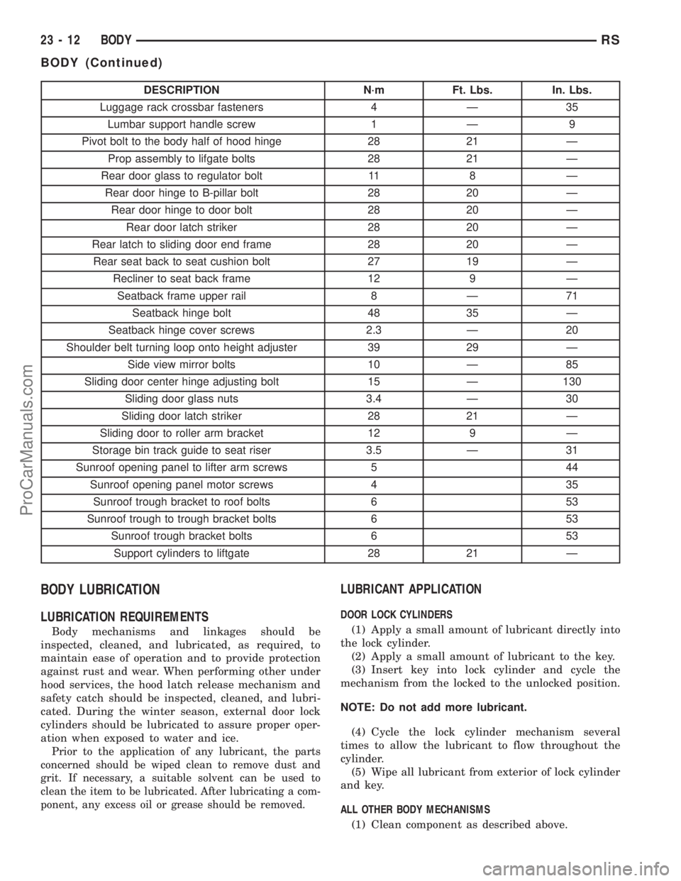
DESCRIPTION N´m Ft. Lbs. In. Lbs.
Luggage rack crossbar fasteners 4 Ð 35
Lumbar support handle screw 1 Ð 9
Pivot bolt to the body half of hood hinge 28 21 Ð
Prop assembly to lifgate bolts 28 21 Ð
Rear door glass to regulator bolt 11 8 Ð
Rear door hinge to B-pillar bolt 28 20 Ð
Rear door hinge to door bolt 28 20 Ð
Rear door latch striker 28 20 Ð
Rear latch to sliding door end frame 28 20 Ð
Rear seat back to seat cushion bolt 27 19 Ð
Recliner to seat back frame 12 9 Ð
Seatback frame upper rail 8 Ð 71
Seatback hinge bolt 48 35 Ð
Seatback hinge cover screws 2.3 Ð 20
Shoulder belt turning loop onto height adjuster 39 29 Ð
Side view mirror bolts 10 Ð 85
Sliding door center hinge adjusting bolt 15 Ð 130
Sliding door glass nuts 3.4 Ð 30
Sliding door latch striker 28 21 Ð
Sliding door to roller arm bracket 12 9 Ð
Storage bin track guide to seat riser 3.5 Ð 31
Sunroof opening panel to lifter arm screws 5 44
Sunroof opening panel motor screws 4 35
Sunroof trough bracket to roof bolts 6 53
Sunroof trough to trough bracket bolts 6 53
Sunroof trough bracket bolts 6 53
Support cylinders to liftgate 28 21 Ð
BODY LUBRICATION
LUBRICATION REQUIREMENTS
Body mechanisms and linkages should be
inspected, cleaned, and lubricated, as required, to
maintain ease of operation and to provide protection
against rust and wear. When performing other under
hood services, the hood latch release mechanism and
safety catch should be inspected, cleaned, and lubri-
cated. During the winter season, external door lock
cylinders should be lubricated to assure proper oper-
ation when exposed to water and ice.
Prior to the application of any lubricant, the parts
concerned should be wiped clean to remove dust and
grit. If necessary, a suitable solvent can be used to
clean the item to be lubricated. After lubricating a com-
ponent, any excess oil or grease should be removed.
LUBRICANT APPLICATION
DOOR LOCK CYLINDERS
(1) Apply a small amount of lubricant directly into
the lock cylinder.
(2) Apply a small amount of lubricant to the key.
(3) Insert key into lock cylinder and cycle the
mechanism from the locked to the unlocked position.
NOTE: Do not add more lubricant.
(4) Cycle the lock cylinder mechanism several
times to allow the lubricant to flow throughout the
cylinder.
(5) Wipe all lubricant from exterior of lock cylinder
and key.
ALL OTHER BODY MECHANISMS
(1) Clean component as described above.
23 - 12 BODYRS
BODY (Continued)
ProCarManuals.com
Page 1751 of 2177
HINGE
REMOVAL
(1) Release front door latch and open door.
(2) Mark hinge foot print on both door and pillar
to aid when installing door.
(3) Support door on suitable lifting device.
(4) Remove bolts attaching front door to door
hinge.
(5) Remove bolts attaching hinge to pillar.
(6) Remove door hinge from vehicle.
INSTALLATION
CAUTION: When installing a new hinge, make sure
that the head of each hinge pin is fully seated into
the door hinge. Also, remove the plastic shipping
clip and replace it with the correct metal retaining
clip once the hinge pin is seated.
(1) Paint hinge prior to installation, if necessary.
(2) Position door hinge on vehicle.
(3) Install bolts attaching hinge to pillar. Tighten
bolts to 34 N´m (25 ft. lbs.).
(4) Install bolts attaching front door to door hinge.
Tighten bolts to 34 N´m (25 ft. lbs.).
(5) Align door to achieve equal spacing to sur-
rounding body panels. Panels should be flush across
all gaps.
(6) Verify door alignment and operation. Adjust as
necessary.
LATCH
REMOVAL
(1) Roll door glass up.
(2) Remove front door trim panel. (Refer to 23 -
BODY/DOOR - FRONT/TRIM PANEL - REMOVAL)
(3) Remove watershield as necessary to gain access
to the outside door handle.
(4) Through access hole at rear of inner door
panel, disconnect wire connector from power door
lock motor, if equipped.
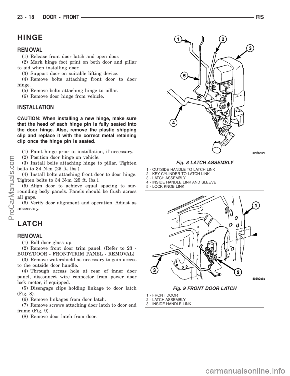
(5) Disengage clips holding linkage to door latch
(Fig. 8).
(6) Remove linkages from door latch.
(7) Remove screws attaching door latch to door end
frame (Fig. 9).
(8) Remove door latch from door.
Fig. 8 LATCH ASSEMBLY
1 - OUTSIDE HANDLE TO LATCH LINK
2 - KEY CYLINDER TO LATCH LINK
3 - LATCH ASSEMBLY
4 - INSIDE HANDLE LINK AND SLEEVE
5 - LOCK KNOB LINK
Fig. 9 FRONT DOOR LATCH
1 - FRONT DOOR
2 - LATCH ASSEMBLY
3 - INSIDE HANDLE LINK
23 - 18 DOOR - FRONTRS
ProCarManuals.com
Page 1753 of 2177
INSTALLATION
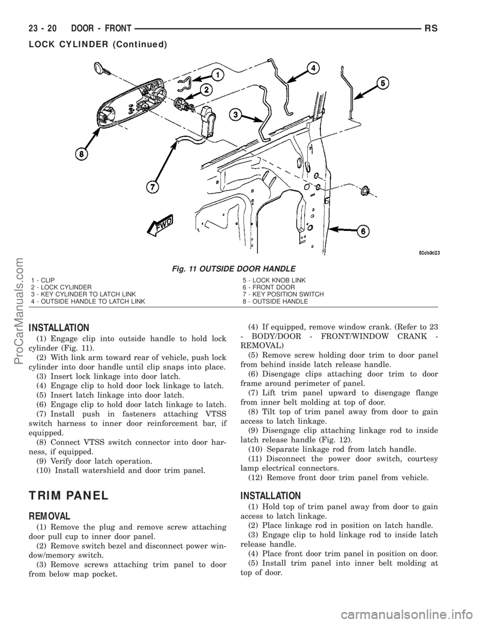
(1) Engage clip into outside handle to hold lock
cylinder (Fig. 11).
(2) With link arm toward rear of vehicle, push lock
cylinder into door handle until clip snaps into place.
(3) Insert lock linkage into door latch.
(4) Engage clip to hold door lock linkage to latch.
(5) Insert latch linkage into door latch.
(6) Engage clip to hold door latch linkage to latch.
(7) Install push in fasteners attaching VTSS
switch harness to inner door reinforcement bar, if
equipped.
(8) Connect VTSS switch connector into door har-
ness, if equipped.
(9) Verify door latch operation.
(10) Install watershield and door trim panel.
TRIM PANEL
REMOVAL
(1) Remove the plug and remove screw attaching
door pull cup to inner door panel.
(2) Remove switch bezel and disconnect power win-
dow/memory switch.
(3) Remove screws attaching trim panel to door
from below map pocket.(4) If equipped, remove window crank. (Refer to 23
- BODY/DOOR - FRONT/WINDOW CRANK -
REMOVAL)
(5) Remove screw holding door trim to door panel
from behind inside latch release handle.
(6) Disengage clips attaching door trim to door
frame around perimeter of panel.
(7) Lift trim panel upward to disengage flange
from inner belt molding at top of door.
(8) Tilt top of trim panel away from door to gain
access to latch linkage.
(9) Disengage clip attaching linkage rod to inside
latch release handle (Fig. 12).
(10) Separate linkage rod from latch handle.
(11) Disconnect the power door switch, courtesy
lamp electrical connectors.
(12) Remove front door trim panel from vehicle.
INSTALLATION
(1) Hold top of trim panel away from door to gain
access to latch linkage.
(2) Place linkage rod in position on latch handle.
(3) Engage clip to hold linkage rod to inside latch
release handle.
(4) Place front door trim panel in position on door.
(5) Install trim panel into inner belt molding at
top of door.
Fig. 11 OUTSIDE DOOR HANDLE
1 - CLIP
2 - LOCK CYLINDER
3 - KEY CYLINDER TO LATCH LINK
4 - OUTSIDE HANDLE TO LATCH LINK5 - LOCK KNOB LINK
6 - FRONT DOOR
7 - KEY POSITION SWITCH
8 - OUTSIDE HANDLE
23 - 20 DOOR - FRONTRS
LOCK CYLINDER (Continued)
ProCarManuals.com
Page 1755 of 2177
EXTERIOR HANDLE
REMOVAL
(1) Roll door glass up.
(2) Remove the watershield as necessary to gain
access to the outside door handle. (Refer to 23 -
BODY/DOOR - FRONT/WATERSHIELD -
REMOVAL)
(3) Through access hole at rear of inner door
panel, disconnect Vehicle Theft Security System
(VTSS) switch connector from door harness, if
equipped.
(4) Disengage push in fasteners attaching VTSS
switch harness to inner door reinforcement bar, if
equipped.
(5) Disengage clip holding door latch linkage to
door latch (Fig. 11).
(6) Remove latch linkage from latch.
(7) Disengage clip holding door lock linkage to
door latch.
(8) Remove lock linkage from latch.
(9) Remove nuts holding outside door handle to
door outer panel.
(10) Remove outside door handle from vehicle.
INSTALLATION
If outside door handle replacement is necessary,
transfer lock cylinder from the original handle to the
new one.
(1) Place outside door handle in position on vehi-
cle.
(2) Install nuts attaching outside door handle to
door outer panel (Fig. 11). Tighten nuts to 6 N´m (50
in. lbs.).
(3) Insert lock linkage into door latch.
(4) Engage clip to hold door lock linkage to latch.
(5) Insert latch linkage into door latch.
(6) Engage clip to hold door latch linkage to latch.
(7) Install push-in fasteners to hold VTSS switch
harness to inner door reinforcement bar, if equipped.
(8) Connect VTSS switch connector into door har-
ness, if equipped.
(9) Verify door latch operation.
(10) Install sound shield and door trim panel.
WINDOW REGULATOR -
POWER
REMOVAL
(1) Remove watershield. (Refer to 23 - BODY/
DOOR - FRONT/WATERSHIELD - REMOVAL)
(2) Remove inner belt molding.(Refer to 23 -
BODY/WEATHERSTRIP/SEALS/FDR INNER BELT
WEATHERSTRIP - REMOVAL)(3) Remove door glass. (Refer to 23 - BODY/DOOR
- FRONT/DOOR GLASS - REMOVAL).
(4) Disconnect wire connector from power window
motor.
(5) Loosen screws attaching front and rear window
guide rails to inner door panel.
(6) Remove screw heads on guide rails from key
hole slots in inner door panel.
(7) Loosen screws attaching motor/housing to inner
door panel.
(8) Remove regulator from inner door panel.
(9) Extract rear guide rail through inner door
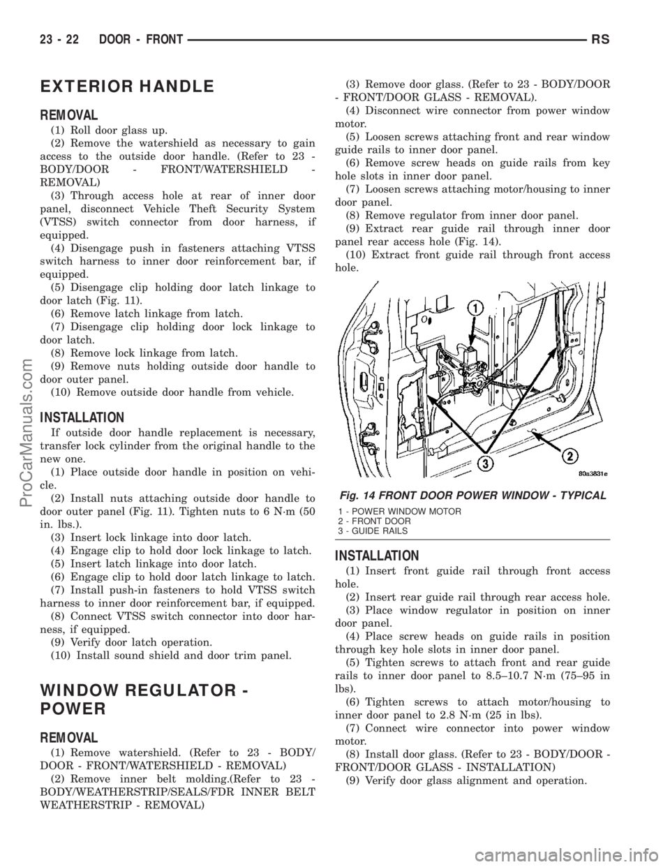
panel rear access hole (Fig. 14).
(10) Extract front guide rail through front access
hole.
INSTALLATION
(1) Insert front guide rail through front access
hole.
(2) Insert rear guide rail through rear access hole.
(3) Place window regulator in position on inner
door panel.
(4) Place screw heads on guide rails in position
through key hole slots in inner door panel.
(5) Tighten screws to attach front and rear guide
rails to inner door panel to 8.5±10.7 N´m (75±95 in
lbs).
(6) Tighten screws to attach motor/housing to
inner door panel to 2.8 N´m (25 in lbs).
(7) Connect wire connector into power window
motor.
(8) Install door glass. (Refer to 23 - BODY/DOOR -
FRONT/DOOR GLASS - INSTALLATION)
(9) Verify door glass alignment and operation.
Fig. 14 FRONT DOOR POWER WINDOW - TYPICAL
1 - POWER WINDOW MOTOR
2 - FRONT DOOR
3 - GUIDE RAILS
23 - 22 DOOR - FRONTRS
ProCarManuals.com
Page 1756 of 2177
(10) Install inner belt molding (Refer to 23 -
BODY/WEATHERSTRIP/SEALS/FDR INNER BELT
WEATHERSTRIP - INSTALLATION)
(11) Install watershield. (Refer to 23 - BODY/
DOOR - FRONT/WATERSHIELD - INSTALLATION)
WINDOW REGULATOR -
MANUAL
REMOVAL
(1) Remove watershield. (Refer to 23 - BODY/
DOOR - FRONT/WATERSHIELD - REMOVAL)
(2) Remove inner belt molding.(Refer to 23 -
BODY/WEATHERSTRIP/SEALS/FDR INNER BELT
WEATHERSTRIP - REMOVAL)
(3) Remove door glass. (Refer to 23 - BODY/DOOR
- FRONT/DOOR GLASS - REMOVAL).
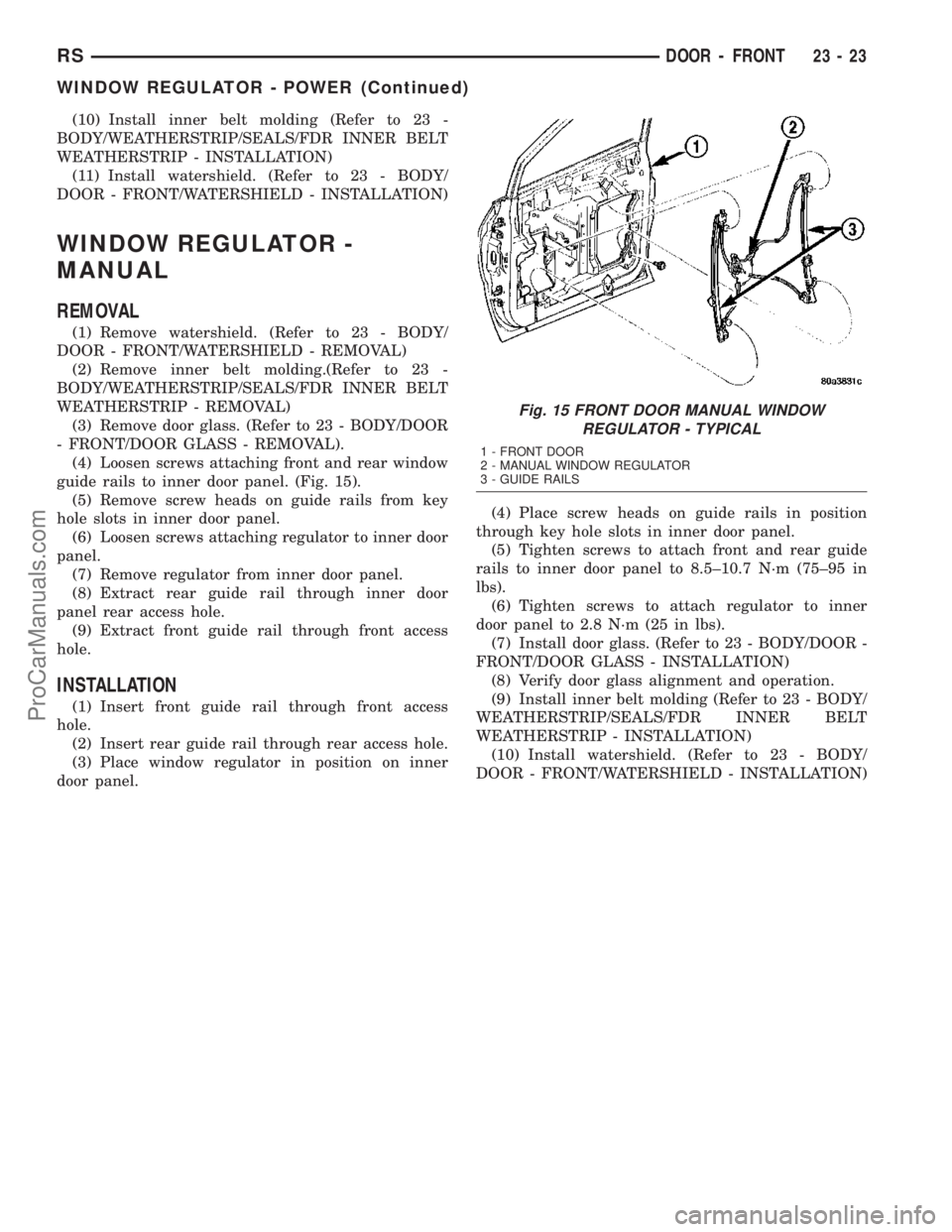
(4) Loosen screws attaching front and rear window
guide rails to inner door panel. (Fig. 15).
(5) Remove screw heads on guide rails from key
hole slots in inner door panel.
(6) Loosen screws attaching regulator to inner door
panel.
(7) Remove regulator from inner door panel.
(8) Extract rear guide rail through inner door
panel rear access hole.
(9) Extract front guide rail through front access
hole.
INSTALLATION
(1) Insert front guide rail through front access
hole.
(2) Insert rear guide rail through rear access hole.
(3) Place window regulator in position on inner
door panel.(4) Place screw heads on guide rails in position
through key hole slots in inner door panel.
(5) Tighten screws to attach front and rear guide
rails to inner door panel to 8.5±10.7 N´m (75±95 in
lbs).
(6) Tighten screws to attach regulator to inner
door panel to 2.8 N´m (25 in lbs).
(7) Install door glass. (Refer to 23 - BODY/DOOR -
FRONT/DOOR GLASS - INSTALLATION)
(8) Verify door glass alignment and operation.
(9) Install inner belt molding (Refer to 23 - BODY/
WEATHERSTRIP/SEALS/FDR INNER BELT
WEATHERSTRIP - INSTALLATION)
(10) Install watershield. (Refer to 23 - BODY/
DOOR - FRONT/WATERSHIELD - INSTALLATION)
Fig. 15 FRONT DOOR MANUAL WINDOW
REGULATOR - TYPICAL
1 - FRONT DOOR
2 - MANUAL WINDOW REGULATOR
3 - GUIDE RAILS
RSDOOR - FRONT23-23
WINDOW REGULATOR - POWER (Continued)
ProCarManuals.com
Page 1767 of 2177
(8) Install screw to hold top of inside release han-
dle to sliding door.
(9) Install screws to hold bottom of inside latch
handle to sliding door.
(10) Verify sliding door operation. Adjust as neces-
sary. (Refer to 23 - BODY/DOORS - SLIDING/SLID-
ING DOOR - ADJUSTMENTS)
(11) Install sliding door trim panel.(Refer to 23 -
BODY/DOORS - SLIDING/TRIM PANEL - INSTAL-
LATION)
BELLCRANK
REMOVAL
(1) Remove stop bumper (Refer to 23 - BODY/
DOORS - SLIDING/STOP BUMPER - REMOVAL).
(2) Remove sliding door trim panel. (Refer to 23 -
BODY/DOORS - SLIDING/TRIM PANEL -
REMOVAL)
(3) Peel watershield away from adhesive around
perimeter of inner door panel as necessary to gain
access to latch bellcrank.
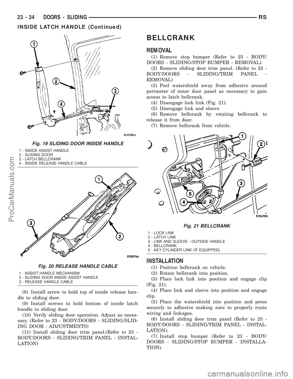
(4) Disengage lock link (Fig. 21).
(5) Disengage link and sleeve
(6) Remove bellcrank by rotating bellcrank to
release it from door.
(7) Remove bellcrank from vehicle.
INSTALLATION
(1) Position bellcrank on vehicle.
(2) Rotate bellcrank into position.
(3) Place lock link into position and engage clip
(Fig. 21).
(4) Place link and sleeve into position and engage
clip.
(5) Place the watershield into position and press
securely to adhesive making sure to properly route
wiring and linkages.
(6) Install sliding door trim panel (Refer to 23 -
BODY/DOORS - SLIDING/TRIM PANEL - INSTAL-
LATION).
(7) Install stop bumper (Refer to 23 - BODY/
DOORS - SLIDING/STOP BUMPER - INSTALLA-
TION).
Fig. 19 SLIDING DOOR INSIDE HANDLE
1 - INSIDE ASSIST HANDLE
2 - SLIDING DOOR
3 - LATCH BELLCRANK
4 - INSIDE RELEASE HANDLE CABLE
Fig. 20 RELEASE HANDLE CABLE
1 - ASSIST HANDLE MECHANISM
2 - SLIDING DOOR INSIDE ASSIST HANDLE
3 - RELEASE HANDLE CABLE
Fig. 21 BELLCRANK
1 - LOCK LINK
2 - LATCH LINK
3 - LINK AND SLEEVE - OUTSIDE HANDLE
4 - BELLCRANK
5 - KEY CYLINDER LINK (IF EQUIPPED)
23 - 34 DOORS - SLIDINGRS
INSIDE LATCH HANDLE (Continued)
ProCarManuals.com
Page 1768 of 2177
OUTSIDE HANDLE
REMOVAL
(1) Remove sliding door trim panel. (Refer to 23 -
BODY/DOORS - SLIDING/TRIM PANEL -
REMOVAL)
(2) Remove sliding door stop bumper. (Refer to 23 -
BODY/DOORS - SLIDING/STOP BUMPER -
REMOVAL)
(3) Peel watershield away from adhesive around
perimeter of inner door panel as necessary to access
outside release handle fasteners.
(4) Disengage clip attaching outside door handle
linkage to door cable.
(5) Remove linkage from outside door handle.
(6) Remove three nuts attaching outside door han-
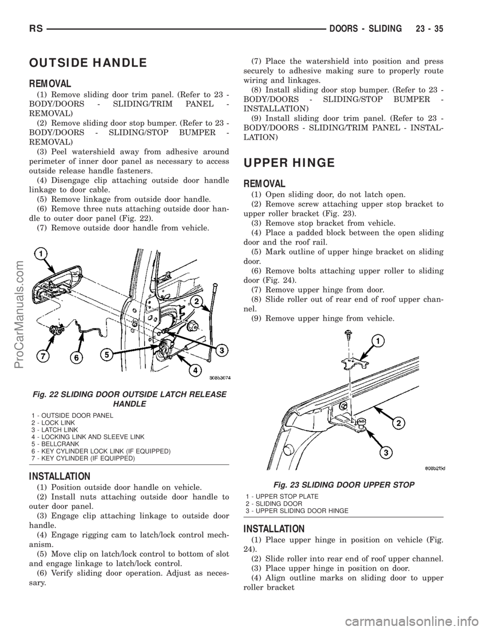
dle to outer door panel (Fig. 22).
(7) Remove outside door handle from vehicle.
INSTALLATION
(1) Position outside door handle on vehicle.
(2) Install nuts attaching outside door handle to
outer door panel.
(3) Engage clip attaching linkage to outside door
handle.
(4) Engage rigging cam to latch/lock control mech-
anism.
(5) Move clip on latch/lock control to bottom of slot
and engage linkage to latch/lock control.
(6) Verify sliding door operation. Adjust as neces-
sary.(7) Place the watershield into position and press
securely to adhesive making sure to properly route
wiring and linkages.
(8) Install sliding door stop bumper. (Refer to 23 -
BODY/DOORS - SLIDING/STOP BUMPER -
INSTALLATION)
(9) Install sliding door trim panel. (Refer to 23 -
BODY/DOORS - SLIDING/TRIM PANEL - INSTAL-
LATION)
UPPER HINGE
REMOVAL
(1) Open sliding door, do not latch open.
(2) Remove screw attaching upper stop bracket to
upper roller bracket (Fig. 23).
(3) Remove stop bracket from vehicle.
(4) Place a padded block between the open sliding
door and the roof rail.
(5) Mark outline of upper hinge bracket on sliding
door.
(6) Remove bolts attaching upper roller to sliding
door (Fig. 24).
(7) Remove upper hinge from door.
(8) Slide roller out of rear end of roof upper chan-
nel.
(9) Remove upper hinge from vehicle.
INSTALLATION
(1) Place upper hinge in position on vehicle (Fig.
24).
(2) Slide roller into rear end of roof upper channel.
(3) Place upper hinge in position on door.
(4) Align outline marks on sliding door to upper
roller bracket
Fig. 22 SLIDING DOOR OUTSIDE LATCH RELEASE
HANDLE
1 - OUTSIDE DOOR PANEL
2 - LOCK LINK
3 - LATCH LINK
4 - LOCKING LINK AND SLEEVE LINK
5 - BELLCRANK
6 - KEY CYLINDER LOCK LINK (IF EQUIPPED)
7 - KEY CYLINDER (IF EQUIPPED)
Fig. 23 SLIDING DOOR UPPER STOP
1 - UPPER STOP PLATE
2 - SLIDING DOOR
3 - UPPER SLIDING DOOR HINGE
RSDOORS - SLIDING23-35
ProCarManuals.com
Page 1793 of 2177
INSTALLATION
(1) Place hood in position on vehicle. With assis-
tance from a helper at the opposite side of the vehicle
to support the hood, install bottom bolts attaching
hood to hinge finger tight.
(2) Install top bolts attaching hood to hinge finger
tight.
(3) Position bolts at marks and tighten. Tighten
bolts to 13.5 N´m (120 in. lbs.) torque. The hood
should be aligned to 4 mm (0.160 in.) gap to the front
fenders and flush across the top surfaces along fend-
ers.
(4) Verify hood operation and alignment.
LATCH
REMOVAL
(1) Release hood latch and open hood.
(2) Remove bolts attaching hood latch to radiator
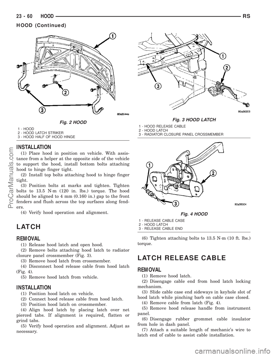
closure panel crossmember (Fig. 3).
(3) Remove hood latch from crossmember.
(4) Disconnect hood release cable from hood latch
(Fig. 4).
(5) Remove hood latch from vehicle.
INSTALLATION
(1) Position hood latch on vehicle.
(2) Connect hood release cable from hood latch.
(3) Position hood latch on crossmember.
(4) Align hood latch by placing latch over net
pierced tabs. If alignment is required, flatten or
grind tabs.
(5) Verify hood operation and alignment. Adjust as
necessary.(6) Tighten attaching bolts to 13.5 N´m (10 ft. lbs.)
torque.
LATCH RELEASE CABLE
REMOVAL
(1) Remove hood latch.
(2) Disengage cable end from hood latch locking
mechanism.
(3) Slide cable case end sideways in keyhole slot of
hood latch while pinching barb on cable case closed.
(4) Remove cable from latch (Fig. 4).
(5) Remove hood release handle from instrument
panel.
(6) Disengage rubber grommet cable insulator
from hole in dash panel.
(7) Attach a suitable length of mechanic's wire to
latch end of cable to assist cable installation.
Fig. 2 HOOD
1 - HOOD
2 - HOOD LATCH STRIKER
3 - HOOD HALF OF HOOD HINGE
Fig. 3 HOOD LATCH
1 - HOOD RELEASE CABLE
2 - HOOD LATCH
3 - RADIATOR CLOSURE PANEL CROSSMEMBER
Fig. 4 HOOD
1 - RELEASE CABLE CASE
2 - HOOD LATCH
3 - RELEASE CABLE END
23 - 60 HOODRS
HOOD (Continued)
ProCarManuals.com