Page 122 of 162

122
Coolant
Do not add coolant to the cooling
system when the engine is hot. If
you attempt to do so, escaping coolant
can cause burns.
Antifreeze and anti-corrosion agents
are hazardous to health. You should
always store them in their closed origi-
nal containers and in a location which is
out of reach of children. Antifreeze and
anti-corrosion agents are inflammable.
For this reason, do not spill them on hot
engine parts. They could ignite and
cause burns. Comply with the instruc-
tions on the containers.<
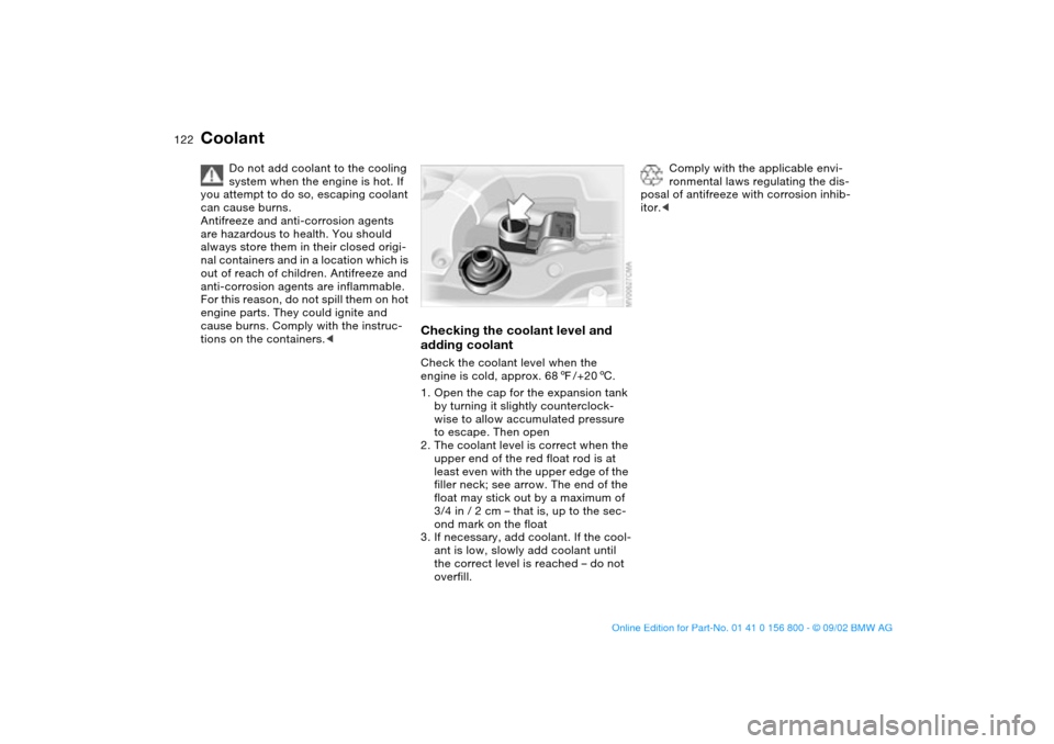
Checking the coolant level and
adding coolantCheck the coolant level when the
engine is cold, approx. 687/+206.
1. Open the cap for the expansion tank
by turning it slightly counterclock-
wise to allow accumulated pressure
to escape. Then open
2. The coolant level is correct when the
upper end of the red float rod is at
least even with the upper edge of the
filler neck; see arrow. The end of the
float may stick out by a maximum of
3/4 in / 2 cm – that is, up to the sec-
ond mark on the float
3. If necessary, add coolant. If the cool-
ant is low, slowly add coolant until
the correct level is reached – do not
overfill.
Comply with the applicable envi-
ronmental laws regulating the dis-
posal of antifreeze with corrosion inhib-
itor.<
handbook.book Page 122 Tuesday, July 30, 2002 12:16 PM
Page 127 of 162
127
engine misfiring for even a short period
of time can seriously damage emission
control system components, especially
the catalytic converter.
Service Engine Soon warning
lamp for Canadian models.
If the fuel filler cap is not on tight
enough, the OBD system can
detect leaking vapor and the indicator
will light up. If the fuel filler cap is then
tightened, the indicator will usually go
out after a short period of time.
OverviewControlsMaintenanceRepairsDataIndex
handbook.book Page 127 Tuesday, July 30, 2002 12:16 PM
Page 131 of 162

131
Lamps and bulbsThe lamps and bulbs make essential
contributions to the safety of your vehi-
cle. Therefore, comply fully with the fol-
lowing instructions during bulb replace-
ment. If you are not familiar with any of
the procedures, consult your BMW
center.
Do not touch the glass portion of
a new bulb with your bare hands
since even small amounts of impurities
burn in to the surface and reduce the
service life of the bulb. Use a clean
cloth, paper napkin, or a similar mate-
rial, or hold the bulb by its metallic
base.<
A replacement bulb set is available from
your BMW center.
Before working on the electrical
system, switch off the electrical
accessory you are working on or dis-
connect the cable from the negative
terminal of the battery. Failure to
observe this precaution could result in
short circuits.
To prevent injuries and damage, com-
ply with any instructions provided by
the bulb manufacturer.<
Low beams and high beamsEngine compartment, left side:
1Low beams
2High beams
H7 bulb, 55 watt
The H7 bulb is pressurized. There-
fore, wear safety glasses and pro-
tective gloves. Failure to comply with
this precaution could lead to injury if the
bulb is damaged.<
1. Turn the two release catches at the
front to the left – see arrow – to
remove the bulb holder
2. Remove and replace the bulb.
When cleaning the headlamps,
please follow the instructions in
the Caring for your vehicle brochure.<
Xenon lamps*The service life of these bulbs is very
long and the probability of a failure is
very low, provided that they are not
switched on and off an unusual number
of times. If one of these bulbs should
nevertheless fail, it is possible to con-
tinue driving with great caution using
the fog lamps, provided local traffic
laws do not prohibit this.
Because of the extremely high
voltages involved, any work on the
xenon lighting system, including bulb-
changing, should be carried out by
technically-qualified personnel only.
Otherwise, there is a risk of fatal
injury.<
OverviewControlsMaintenanceRepairsDataIndex
handbook.book Page 131 Tuesday, July 30, 2002 12:16 PM
Page 132 of 162
132
Parking lamps5 watt bulb
Engine compartment, left side:
1. Turn the bulb holder to the left – see
arrow – and remove
2. Remove and replace the bulb.
Front turn signal indicators21 watt bulb
1. Using a long screwdriver, release the
inner clamp through the upper open-
ing
2. Remove the lamp by pulling it out
toward the front
3. Applying light pressure, turn the bulb
to the left. Remove and replace the
bulb
4. Insert the 2 pins on the lamp into the
guides on the vehicle
5. Push the lamp in. Carefully apply
pressure until you hear it snap into
place.
Lamps and bulbs
handbook.book Page 132 Tuesday, July 30, 2002 12:16 PM
Page 133 of 162

133
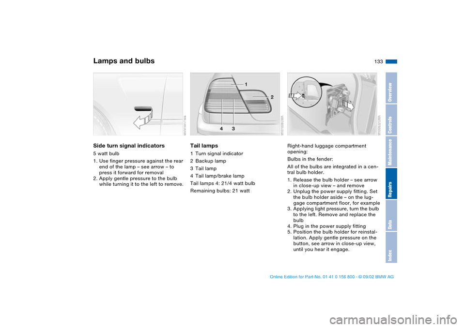
Side turn signal indicators5 watt bulb
1. Use finger pressure against the rear
end of the lamp – see arrow – to
press it forward for removal
2. Apply gentle pressure to the bulb
while turning it to the left to remove.
Tail lamps1Turn signal indicator
2Backup lamp
3Tail lamp
4Tail lamp/brake lamp
Tail lamps 4: 21/4 watt bulb
Remaining bulbs: 21 watt
Right-hand luggage compartment
opening:
Bulbs in the fender:
All of the bulbs are integrated in a cen-
tral bulb holder.
1. Release the bulb holder – see arrow
in close-up view – and remove
2. Unplug the power supply fitting. Set
the bulb holder aside – on the lug-
gage compartment floor, for example
3. Applying light pressure, turn the bulb
to the left. Remove and replace the
bulb
4. Plug in the power supply fitting
5. Position the bulb holder for reinstal-
lation. Apply gentle pressure on the
button, see arrow in close-up view,
until you hear it engage.
Lamps and bulbs
OverviewControlsMaintenanceRepairsDataIndex
handbook.book Page 133 Tuesday, July 30, 2002 12:16 PM
Page 134 of 162
134
Bulbs in the luggage compartment lid
1. Using a screwdriver, loosen the clip
2. Swing trim panel down – see arrow 1.
Release the bulb holder – see arrow
2 – and remove it
3. Applying light pressure, turn the bulb
to the left. Remove and replace the
bulb
4. Press the bulb holder into place,
continuing until you hear it engage
5. Reinstall the trim panel with the clip.
Center high-mount brake lampLED strip on the rear window.
Please contact your BMW center in
case of a malfunction.
Lamps and bulbs
handbook.book Page 134 Tuesday, July 30, 2002 12:16 PM
Page 138 of 162

138
13. Wheels with full wheel covers*:
place the wheel cover with the
valve opening – see arrow – over
the valve. Use both hands to press
the cover securely onto the rim
14. Check and correct the tire inflation
pressure at the earliest opportunity.
Vehicles with Tire Pressure Monitor
(TPM)/Flat Tire Monitor: after
mounting the spare tire or correct-
ing the tire inflation pressure, reini-
tialize the system, refer to
pages 81, 82.
Protect valve stems and valves from dirt
using screw-on valve stem caps. Dirty
valve stems frequently lead to slow
pressure loss.
Do not attempt to install the full
wheel cover on the space-saver
spare tire, since this could damage the
cover.<
The vehicle jack is designed for
changing wheels only. Do not
attempt to raise another vehicle model
with it or to raise any load of any kind.
To do so could cause accidents and
personal injury.
To ensure continued safety, have the
tightness of the torque bolts checked
with a calibrated lug wrench – torque
specification: 88.5 lb ft/120 Nm – at the
earliest opportunity.<
When storing a wheel in the spare tire
recess, take care to avoid bending the
threaded rod.
If the original BMW light-alloy wheels
have been replaced with other light-
alloy wheels, different lug bolts may be
required.
Replace the defective tire as soon as
possible and have the new wheel/tire
balanced.
Driving with the space-saver
spare tireDrive cautiously. Do not exceed a
speed of 50 mph / 80 km/h.
Be aware that vehicle handling may be
altered. Anticipate, e.g., reduced track-
ing during braking, longer braking dis-
tances and changed steering charac-
teristics when approaching limit
conditions. These handling characteris-
tics will be even more pronounced if
winter tires are mounted.
Only one space-saver spare tire
may be mounted at one time.
Mount a wheel and tire of the original
size at the earliest possible opportu-
nity.
For certain wheel/tire combina-
tions, the size of the spare tire will
differ from that of the remaining tires.
The spare tire is fully functional at all
loads and speeds. However, the spare
tire should be replaced at the earliest
possible opportunity in order to achieve
the original operating conditions.<
Changing a wheel
handbook.book Page 138 Tuesday, July 30, 2002 12:16 PM
Page 139 of 162

139
Run Flat tires*Run Flat tires are labeled on the side-
wall with a circular symbol containing
the letters RSC. Run Flat tires consist of
self-supporting tires and special rims.
The tire reinforcement ensures that the
tire retains some residual safety in the
event of pressure drop and driving
remains possible to a restricted degree.
The vehicle is equipped with the Flat
Tire Monitor or Tire Pressure Monitor
(TPM), which indicate a flat tire.
Because the sides of Run Flat
tires are reinforced, a drop in infla-
tion pressure usually cannot be
detected from the outside.<
Flat tireIf there is a tire failure, the red warning
lamp symbol lights up. This visual alert
is accompanied by an acoustic warning
signal.
Additional information on the Tire Pres-
sure Monitor or Flat Tire Monitor is
found beginning on page 81.
Reduce vehicle speed carefully to
under 50 mph / 80 km/h, avoiding hard
brake applications and steering maneu-
vers.
If it can not be determined immediately
from the outside which wheel is defec-
tive, check the tire inflation pressure at
all four wheels.
Have Run Flat tires replaced by
your BMW center. In the interest
of safety, Run Flat tires should not be
repaired. Your BMW center has the
information needed for working with
Run Flat tires and is equipped with the
necessary special tools.<
If appropriate, please consult your
BMW center to reequip your vehi-
cle from summer to winter tires – or vice
versa.<
Driving with a damaged tireRun Flat tires allow you to continue
driving to a restricted degree at a maxi-
mum speed of 50 mph / 80 km/h
depending on the cargo load and the
extent of tire damage. You can deter-
mine the distance you may continue
driving on the basis of the following val-
ues:
>Tire inflation pressure of 0 psi/
0 kilopascal (kPa):
approx. 100 miles/150 km
>Tire inflation pressure of approx.
7-15 psi/50-100 kPa:
approx. 300 miles/500 km
>Tire inflation pressure greater than
15 psi/100 kPa:
approx. 600 miles/1,000 km.
Drive cautiously. Do not exceed a
speed of 50 mph / 80 km/h. Be
aware that vehicle handling will be
altered when there is a loss in inflation
pressure. Anticipate, e.g., reduced
tracking during braking, longer braking
distances and changed steering char-
acteristics.<
OverviewControlsMaintenanceRepairsDataIndex
handbook.book Page 139 Tuesday, July 30, 2002 12:16 PM