2003 BMW 325xi TOURING ECU
[x] Cancel search: ECUPage 111 of 166

111
Roof-mounted luggage rack*A special roof-rack system is available
as an optional extra for your BMW.
Please observe the precautions
included with the installation instruc-
tions.AnchoragesAccess to the anchorages:
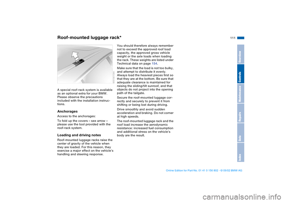
To fold up the covers – see arrow –
please use the tool provided with the
roof-rack system.Loading and driving notesRoof-mounted luggage racks raise the
center of gravity of the vehicle when
they are loaded. For this reason, they
exercise a major effect on the vehicle's
handling and steering response.
You should therefore always remember
not to exceed the approved roof load
capacity, the approved gross vehicle
weight or the axle loads when loading
the rack. These weights are listed under
Technical data on page 154.
Make sure that the load is not too bulky,
and attempt to distribute it evenly.
Always load the heaviest pieces first so
that they are at the bottom. Be sure that
adequate clearance is maintained for
raising the sliding/tilt sunroof, and that
objects do not project into the opening
path of the tailgate.
Secure the roof-mounted luggage cor-
rectly and securely to prevent it from
shifting or being lost during driving.
Drive smoothly and avoid sudden
acceleration and braking. Do not corner
at high speeds.
The roof-mounted luggage rack and the
roof load increase the aerodynamic
resistance: increased fuel consumption
and additional stress on the vehicle's
body are the result.
OverviewControlsMaintenanceRepairsDataIndex
handbook.book Page 111 Saturday, July 27, 2002 1:36 PM
Page 122 of 166

122In the engine compartment
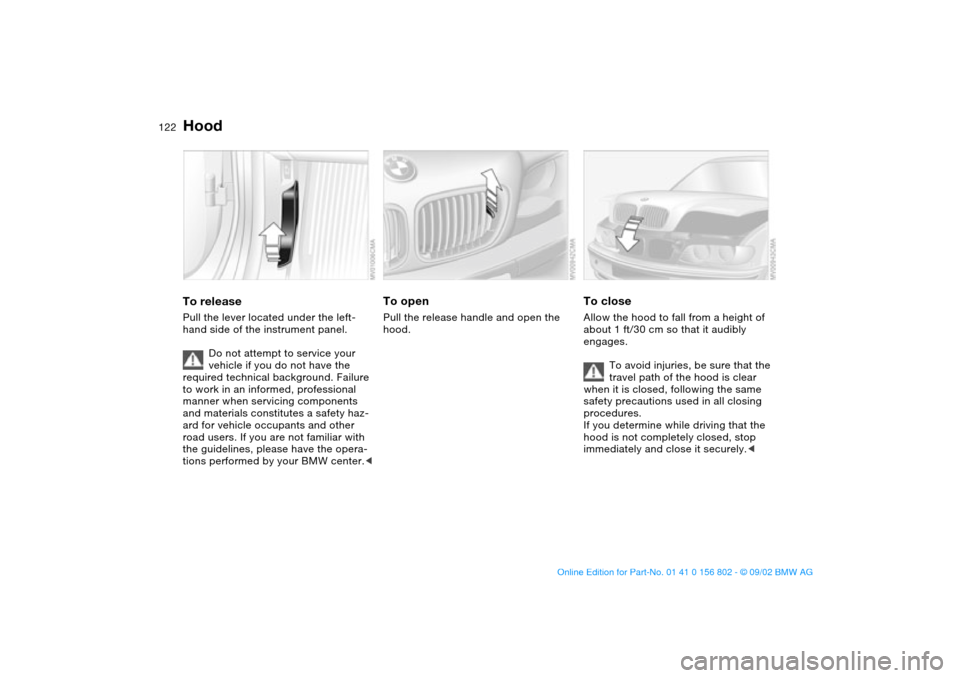
HoodTo releasePull the lever located under the left-
hand side of the instrument panel.
Do not attempt to service your
vehicle if you do not have the
required technical background. Failure
to work in an informed, professional
manner when servicing components
and materials constitutes a safety haz-
ard for vehicle occupants and other
road users. If you are not familiar with
the guidelines, please have the opera-
tions performed by your BMW center.<
To openPull the release handle and open the
hood.
To closeAllow the hood to fall from a height of
about 1 ft/30 cm so that it audibly
engages.
To avoid injuries, be sure that the
travel path of the hood is clear
when it is closed, following the same
safety precautions used in all closing
procedures.
If you determine while driving that the
hood is not completely closed, stop
immediately and close it securely.<
handbook.book Page 122 Saturday, July 27, 2002 1:36 PM
Page 142 of 166

142
Your BMW is equipped with a spare tire
or a space-saver spare tire designed for
temporary use in maintaining the vehi-
cle's mobility in an emergency.
To remove the spare tire, lift the
floor panel in the cargo area com-
pletely out, refer to page 109.<
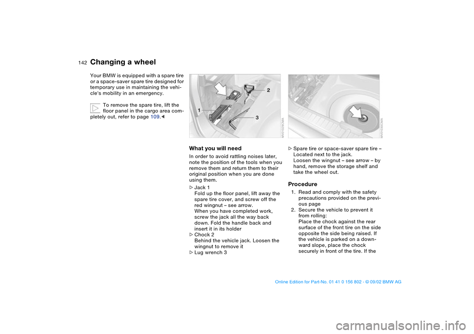
What you will needIn order to avoid rattling noises later,
note the position of the tools when you
remove them and return them to their
original position when you are done
using them.
>Jack 1
Fold up the floor panel, lift away the
spare tire cover, and screw off the
red wingnut – see arrow.
When you have completed work,
screw the jack all the way back
down. Fold the handle back and
insert it in its holder
>Chock 2
Behind the vehicle jack. Loosen the
wingnut to remove it
>Lug wrench 3
>Spare tire or space-saver spare tire –
Located next to the jack.
Loosen the wingnut – see arrow – by
hand, remove the storage shelf and
take the wheel out.Procedure1. Read and comply with the safety
precautions provided on the previ-
ous page
2. Secure the vehicle to prevent it
from rolling:
Place the chock against the rear
surface of the front tire on the side
opposite the side being raised. If
the vehicle is parked on a down-
ward slope, place the chock
securely in front of the tire. If the
Changing a wheel
handbook.book Page 142 Saturday, July 27, 2002 1:36 PM
Page 143 of 166

143
wheel must be changed on a sur-
face with a more severe slope, take
additional precautions to secure
the vehicle from rolling
3. Wheels with full wheel covers*:
reach into the ventilation openings
and pull the cover off
4. Loosen the lug bolts by rotating
half a turn
5. Position the jack at the jacking
point – see arrows – closest to the
flat tire so that the jack base is ver-
tically below the jacking point and
the entire surface of the head of the
jack moves into the square recess
of the jacking point when the jack
is cranked – refer to the detail in the
next illustration
6. Jack the vehicle up until the wheel
you are changing is raised from the
ground
7. Unscrew the lug bolts and remove
the wheel
8. Remove accumulations of mud or
dirt from the mounting surfaces of
the wheel and hub. Clean the lug
bolts
9. Position the new wheel or the
space-saver spare tire on the hub
and screw at least two lug bolts fin-
ger-tight into opposite bolt holes
10. Screw in the remaining lug bolts.
Screw in all the bolts in a diagonal
pattern
11. Lower the jack and remove it from
beneath the vehicle
12. Tighten the lug bolts securely in a
diagonal pattern
Changing a wheel
OverviewControlsMaintenanceRepairsDataIndex
handbook.book Page 143 Saturday, July 27, 2002 1:36 PM
Page 144 of 166

144
13. Wheels with full wheel covers*:
place the wheel cover with the
valve opening – see arrow – over
the valve. Use both hands to press
the cover securely onto the rim
14. Check and correct the tire inflation
pressure at the earliest opportunity.
Vehicles with Tire Pressure Monitor
(TPM)/Flat Tire Monitor: after
mounting the spare tire or correct-
ing the inflation pressure, reinitial-
ize the system, refer to page 85
or 86.
Protect valve stems and valves from dirt
using screw-on valve stem caps. Dirty
valve stems frequently lead to slow
pressure loss.
Do not attempt to install the full
wheel cover on the space-saver
spare tire, since this could damage the
cover.<
The vehicle jack is designed for
changing wheels only. Do not
attempt to raise another vehicle model
with it or to raise any other type of load.
To do so could cause accidents and
personal injury.
To ensure continued safety, have the
tightness of the torque bolts checked
with a calibrated lug wrench – torque
specification: 88.5 lb ft/120 Nm – at the
earliest opportunity.<
When storing a wheel in the spare tire
recess, take care to avoid bending the
threaded rod.
If the original BMW light-alloy wheels
have been replaced with other light-
alloy wheels, different lug bolts may be
required.
Replace the defective tire as soon as
possible and have the new wheel/tire
balanced.
Driving with the space-saver
spare tireDrive cautiously. Do not exceed a
speed of 50 mph / 80 km/h.
Be aware that vehicle handling may be
altered. Anticipate, e.g., reduced track-
ing during braking, longer braking dis-
tances, and changed steering charac-
teristics when approaching limit
conditions. These handling characteris-
tics will be even more pronounced if
winter tires are mounted.
Only one space-saver spare tire
may be mounted at one time.
Mount a wheel and tire of the original
size at the earliest possible opportu-
nity.
tions, the size of the spare tire will
differ from that of the remaining tires.
The spare tire is fully functional at all
loads and speeds. However, the spare
tire should be replaced at the earliest
possible opportunity in order to achieve
the original operating conditions.<
Changing a wheel
handbook.book Page 144 Saturday, July 27, 2002 1:36 PM
Page 146 of 166

146
BatteryMaintenanceThe battery is absolutely maintenance-
free, that is, the original electrolyte will
normally last for the service life of the
battery under moderate climatic condi-
tions.
Please consult your BMW center
whenever you have any questions
concerning the battery. Since the bat-
tery is absolutely maintenance-free, the
following is for your information only.<
Never disconnect the battery
when the engine is running; the
ensuing voltage surge would seriously
damage the vehicle's onboard elec-
tronic systems.
Connect the charge cables to the termi-
nals in the engine compartment. For
terminal locations, refer to Jump-start-
ing on page 147.
Return used batteries to a recy-
cling point or your BMW center.
Maintain the battery in an upright posi-
tion for transport and storage. Secure
the battery against tilting during trans-
port.<
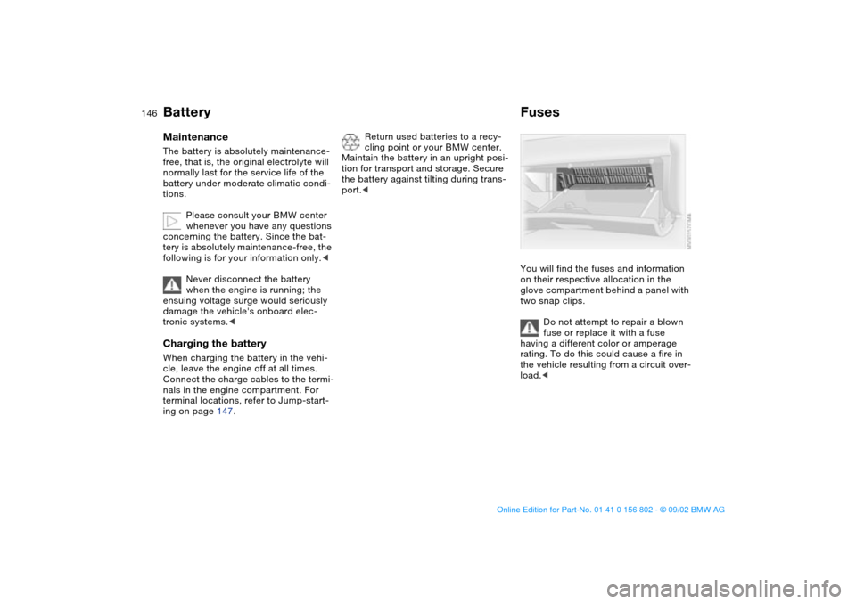
FusesYou will find the fuses and information
on their respective allocation in the
glove compartment behind a panel with
two snap clips.
Do not attempt to repair a blown
fuse or replace it with a fuse
having a different color or amperage
rating. To do this could cause a fire in
the vehicle resulting from a circuit over-
load.<
handbook.book Page 146 Saturday, July 27, 2002 1:36 PM
Page 158 of 166

Everything from A to ZA
ABS Antilock Brake System
18, 115
Accessories 4, 5
Activated-charcoal filter 100
ADB Automatic Differential
Brake 78
Adding brake fluid 129
Air conditioning 92
Air distribution 94, 98
Air nozzles 92, 96
Air outlets 92, 96
Air pressure 117
check 25
Air supply 94, 98
Airbags 18, 52
Alarm system 37
Antifreeze agent 128
Antilock Brake System (ABS)
18, 115
Anti-theft system 37
Armrest 102
ASC+T Automatic Stability
Control plus Traction 18,
19, 78
Ashtray
front 104
rear 104
AUC Automatic recircu-
lated-air control 99Automatic car wash, refer to
the Caring for your vehicle
brochure
Automatic climate control 96
Automatic cruise control 69
Automatic Differential Brake
(ADB) 78
Automatic dimming, interior
rearview mirror 51
Automatic headlamp
control 89
Automatic recirculated-air
control (AUC) 99
Automatic Stability Control
plus Traction (ASC+T) 18,
19, 78
Automatic transmission with
Steptronic 19, 63
Average fuel
consumption 76
Average speed 76
Avoiding unintentional
alarms 38
Axle loads 154
B
Backrest, adjusting 44, 45
Backup lamps 62
replacing bulb 139
Battery
charge 146
discharged 146Battery charge current 18
Belts 47
Beverage holder 103
Blower 94, 98
BMW High Performance
Synthetic Oils 127
BMW sports seat 45, 46
Bore 152
Bottle holder, see Beverage
holder 103
Brake hydraulic system 18
Brake lamps
replacing bulb 139
Brake pads 19
Brake, parking 61
Brakes, malfunctions 116
Break-in procedures 114
Bulb, replacing 137
C
California Proposition 65
warning 132
Can holder, see Beverage
holder 103
Capacities 155
Car care, refer to the Caring
for your vehicle brochure
Car radio
refer to the Owner's Man-
ual for RadioCar telephone
refer to the separate
Owner's Manual
Car vacuum cleaner, con-
necting 104
Car wash, refer to the Caring
for your vehicle brochure
Cargo area 36, 107
capacity 154
emergency operation 35
floor 36
floor panel 109
remote control 32
Cargo area cover 107
Cargo area lamps 34
Cargo loading 109
Cargo, securing 110
Cassette player operation,
refer to the Owner's Man-
ual for Radio
CBC Cornering Brake
Control 18, 115
CD player operation, refer to
the Owner's Manual for
Radio
Cellular phone 103
Center armrest 102
Center high-mount brake
lamp 140
Central locking system 30
button 34
Charge indicator lamp 18
handbook.book Page 158 Saturday, July 27, 2002 1:36 PM
Page 161 of 166

Everything from A to Z
161
N
Navigation System, refer to
the separate Owner's
Manual
Neckrest 47
O
OBD interface socket 132
Obstruction protection 39
Odometer 71
Oil
capacity 155
quality 127
viscosity 127
Oil additives 127
Oil change intervals, refer to
the Service and Warranty
Information Booklet for US
models/Warranty and Ser-
vice Guide Booklet for
Canadian models
Oil consumption 126
Oil dipstick 126
Oil filter change 155
Oil level
checking 126
indicator lamp 18
Oil pressure
indicator lamp 18
OIL SERVICE 73
Oil types 127Onboard computer, refer to
the Owner's Manual for
Onboard Computer
Onboard tool kit 136
Operating elements 14
Outlets, ventilation 92, 96
Outside temperature dis-
play 75
P
Panic mode 32
Park Distance Control
(PDC) 77
Parking aid 77
Parking brake 61
Parking lamps 89
replacing bulb 138
Partition net 107
PDC Park Distance
Control 77
Pocket flashlight 102
Pollen 95, 100
Power output 152
Power seat 46
Power windows
safety switch 40
Pressure, tires 25, 85, 117
monitoring 85
R
Radiator 155Radio, refer to the Owner's
Manual for Radio
Rain sensor 67
Range 76
Reading lamps
front 91
rear 91
Rear lamps 139
Rear window defroster
94, 99
Rearview mirror 50
Recirculated-air mode
94, 99
Reclining seat 44
Refueling 24
Remote control 31
Remote control keys 30
Replacement key 30
Reporting safety defects 6
Reserve indicator lamp 72
Reverse 62
Roof load capacity 154
Roof-mounted luggage
rack 111
Run Flat tires 119, 145
S
Safety belt height adjust-
ment 48
Safety feature 39
Safety instructions 5Seat adjustment 44
mechanical 44
power 46
Seat heating 49
Seat memory 48
Securing cargo 110
Securing devices 110
Selector lever, automatic
transmission 63
Service and Warranty Infor-
mation Booklet 130
Service interval display
73, 130
Shiftlock 63
Side airbags 52
Size 153
Ski bag 106
Sliding/tilt sunroof 40
closing following an elec-
trical malfunction 42
convenience operation 31
remote control 32
Snow chains 121
Socket 104
Spare key 30
Spare tire 141
Speedometer 16
Sports seat 45
Standing lamps 90
Starting problems 59
Starting the engine 59
Steering wheel lock 59
OverviewControlsMaintenanceRepairsDataIndex
handbook.book Page 161 Saturday, July 27, 2002 1:36 PM