2003 BMW 325XI warning light
[x] Cancel search: warning lightPage 107 of 166

107
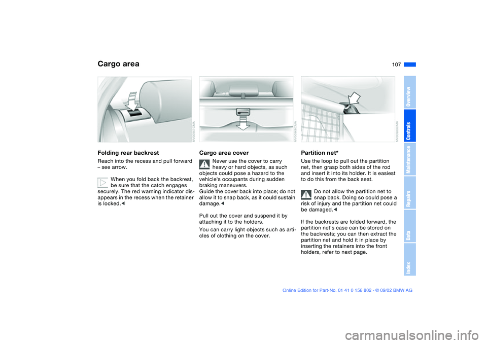
Cargo areaFolding rear backrestReach into the recess and pull forward
– see arrow.
When you fold back the backrest,
be sure that the catch engages
securely. The red warning indicator dis-
appears in the recess when the retainer
is locked.<
Cargo area cover
Never use the cover to carry
heavy or hard objects, as such
objects could pose a hazard to the
vehicle's occupants during sudden
braking maneuvers.
Guide the cover back into place; do not
allow it to snap back, as it could sustain
damage.<
Pull out the cover and suspend it by
attaching it to the holders.
You can carry light objects such as arti-
cles of clothing on the cover.
Partition net*Use the loop to pull out the partition
net, then grasp both sides of the rod
and insert it into its holder. It is easiest
to do this from the back seat.
Do not allow the partition net to
snap back. Doing so could pose a
risk of injury and the partition net could
be damaged.<
If the backrests are folded forward, the
partition net's case can be stored on
the backrests; you can then extract the
partition net and hold it in place by
inserting the retainers into the front
holders, refer to next page.
OverviewControlsMaintenanceRepairsDataIndex
handbook.book Page 107 Saturday, July 27, 2002 1:36 PM
Page 145 of 166

145
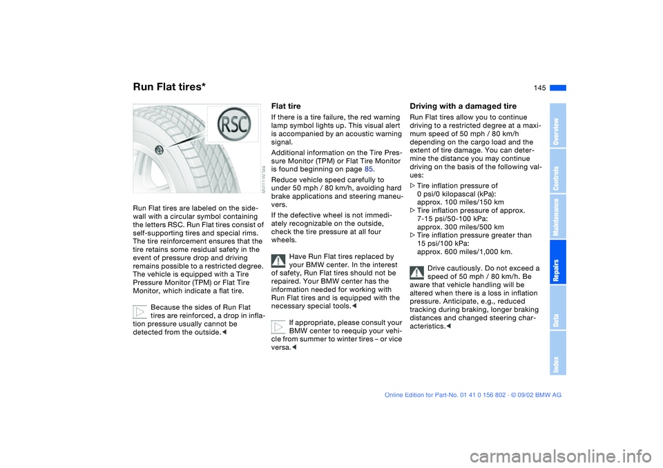
Run Flat tires*Run Flat tires are labeled on the side-
wall with a circular symbol containing
the letters RSC. Run Flat tires consist of
self-supporting tires and special rims.
The tire reinforcement ensures that the
tire retains some residual safety in the
event of pressure drop and driving
remains possible to a restricted degree.
The vehicle is equipped with a Tire
Pressure Monitor (TPM) or Flat Tire
Monitor, which indicate a flat tire.
Because the sides of Run Flat
tires are reinforced, a drop in infla-
tion pressure usually cannot be
detected from the outside.<
Flat tireIf there is a tire failure, the red warning
lamp symbol lights up. This visual alert
is accompanied by an acoustic warning
signal.
Additional information on the Tire Pres-
sure Monitor (TPM) or Flat Tire Monitor
is found beginning on page 85.
Reduce vehicle speed carefully to
under 50 mph / 80 km/h, avoiding hard
brake applications and steering maneu-
vers.
If the defective wheel is not immedi-
ately recognizable on the outside,
check the tire pressure at all four
wheels.
Have Run Flat tires replaced by
your BMW center. In the interest
of safety, Run Flat tires should not be
repaired. Your BMW center has the
information needed for working with
Run Flat tires and is equipped with the
necessary special tools.<
If appropriate, please consult your
BMW center to reequip your vehi-
cle from summer to winter tires – or vice
versa.<
Driving with a damaged tireRun Flat tires allow you to continue
driving to a restricted degree at a maxi-
mum speed of 50 mph / 80 km/h
depending on the cargo load and the
extent of tire damage. You can deter-
mine the distance you may continue
driving on the basis of the following val-
ues:
>Tire inflation pressure of
0 psi/0 kilopascal (kPa):
approx. 100 miles/150 km
>Tire inflation pressure of approx.
7-15 psi/50-100 kPa:
approx. 300 miles/500 km
>Tire inflation pressure greater than
15 psi/100 kPa:
approx. 600 miles/1,000 km.
Drive cautiously. Do not exceed a
speed of 50 mph / 80 km/h. Be
aware that vehicle handling will be
altered when there is a loss in inflation
pressure. Anticipate, e.g., reduced
tracking during braking, longer braking
distances and changed steering char-
acteristics.<
OverviewControlsMaintenanceRepairsDataIndex
handbook.book Page 145 Saturday, July 27, 2002 1:36 PM
Page 147 of 166

147 Giving and receiving assistance
Jump-startingWhen your battery is discharged, you
can use two jumper cables to start your
vehicle with power from the battery in a
second vehicle. You can also use the
same method to help start another
vehicle. Only use jumper cables with
fully insulated handles on the terminal
clamps.
Do not touch high-voltage wiring
and cables on a running engine.
Contact with components carrying high
voltage can be harmful or fatal. Care-
fully observe the following instructions
to avoid personal injury and/or damage
to one or both vehicles.<
1. The battery in the support vehicle
must also be rated at 12 volts. This
information is provided on the battery
label
2. Stop the engine of the support vehi-
cle and switch off all electrical com-
ponents in both vehicles – except for
the hazard warning flashers of the
support vehicle
3. Make absolutely certain that there is
no contact between the bodywork of
the two vehicles – short circuit haz-
ard
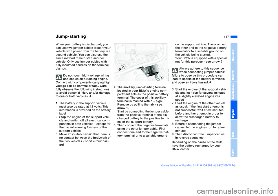
4. The auxiliary jump-starting terminal
located in your BMW's engine com-
partment acts as the positive battery
terminal. The cover of this auxiliary
terminal is marked with a + sign.
Remove by pulling the tab – see
arrow 1.
Start by connecting the jumper cable
from the positive terminal of the dis-
charged battery to the positive termi-
nal of the support battery
5. Then connect the negative terminals
using the other jumper cable. First
connect one end to the negative bat-
tery terminal or to a suitable ground
on the support vehicle. Then connect
the other end to the negative battery
terminal or to a suitable ground on
the vehicle being started.
Your BMW is equipped with a special
nut for this purpose – see arrow 2
Always adhere to this sequence
when connecting jumper cables;
failure to observe this procedure can
lead to sparks at the battery terminals
and pose an injury hazard.<
6. Start the engine of the support vehi-
cle and let it run for several minutes
at a slightly elevated engine idle
speed
7. Start the engine of the other vehicle
as usual. If the first start attempt is
not successful, wait a few minutes
before another attempt in order to
allow the discharged battery to
recharge
8. Before disconnecting the jumper
cables, let the engines run for a few
minutes
9. Then disconnect the jumper cables
in reverse sequence.
Depending on the cause of the fault,
have the battery recharged by your
BMW center.
OverviewControlsMaintenanceRepairsDataIndex
handbook.book Page 147 Saturday, July 27, 2002 1:36 PM
Page 159 of 166

Everything from A to Z
159
Check Control 73
Child-restraint mounting
system (LATCH) 56
Cigarette lighter 104
Clean rear window 68
Clean windshield 68
Clock 74
setting, refer also to the
radio or onboard com-
puter Owner's Manual
Cockpit 14
Code, refer to the Owner's
Manual for Radio
Coin box 102
Compartments 102
Compression ratio 152
Computer 75
Condensation, removing
from windows 95, 98
Consumption 76
display 72
Coolant 128, 155
Cooling system 155
Copyright 4
Cornering Brake Control
(CBC) 18, 115
Cover, refer to Cargo area
cover
Cruise control 69
Cup holder, see Beverage
holder 103
Curb weight 154Cushion height 153
D
Data
dimensions 153
engine 152
technical 152
weights 154
Daytime driving lamps 89
DBC Dynamic Brake
Control 115
Defrost position 95, 98
Defrosting rear window
94, 99
Defrosting, windows 95, 98
Digital clock 74
Dimensions 153
Dipstick, engine oil 126
Displacement 152
Display lighting 90
Displays 16
Distance warning 77
Door key 30
Door lock buttons 34
Doors
emergency operation 33
unlocking and locking 31
Driving notes 115
DSC Dynamic Stability
Control 18, 19, 80
DTC Dynamic Traction
Control 80Dynamic Brake Control
(DBC) 115
Dynamic Stability Control
(DSC) 18, 19, 80
Dynamic Traction Control
(DTC) 80
E
Electric power windows 39
Electrical accessories, fail-
ure 146
Electrical malfunction
fuel filler door 24
sliding/tilt sunroof 42
Emergency operation
doors 33
fuel filler door 24
sliding/tilt sunroof 42
Emissions, minimum, refer
to Energy control 71
Energy control 71
Engine
starting 59
switching off 61
Engine compartment 124
Engine coolant 155
adding 128
temperature gauge 72
Engine data 152Engine oil
adding 126
capacity 155
quality 127
viscosity 127
Engine oil consumption 126
Engine oil level 19
check 126
Engine oil pressure 18
Engine oil types 127
Engine speed 152
Environmentally-friendly
driving, refer to Energy
control 71
Exterior mirrors 50
Eyelet, towing 148
F
Failure messages 73
False alarm, avoiding 38
Fault displays 73
First-aid kit 23
Flashlight 102
Flat tire 117, 141
Flat Tire Monitor 86
Floor panel, lifting 109
Fog lamps 91
Folding rear backrest 107
Follow me home lamps 89
Front fog lamps 91
Front seat adjustment 44
OverviewControlsMaintenanceRepairsDataIndex
handbook.book Page 159 Saturday, July 27, 2002 1:36 PM
Page 160 of 166

Everything from A to ZFrost protection
radiator 128
Fuel consumption 76
Fuel economy, refer to
Energy control 71
Fuel filler door 24
release following an elec-
trical malfunction 24
Fuel gauge 71, 72
Fuel specifications 25
Fuel tank capacity 155
Fuel tank display 72
Fuel tank gauge 72
Fuel-injection system 152
Fuses, replacing 146
G
Gasoline 25
Gasoline gauge 72
Glove compartment 101
Grills 92, 96
Gross vehicle weight 154
H
Hands-free system 103
Harman Kardon premium
sound system 101
Hazard warning flashers 14
Hazard warning triangle 23
HDC Hill Descent Control 84
Head airbags 52
Head restraints 47Headlamp flasher 90
Headlamp washer system
126, 155
Headlamps
automatic control 89
Heated seats 49
Heating and ventilation 96
High beams 21, 66, 90
replacing bulb 137
Hill Descent Control
(HDC) 84
Holder for
beverages 103
litter bag 103
Hood release 122
Horn 14
Hydroplaning 117
I
Ice warning 75
Icy roads 75
Ignition key 30
Ignition lock 59
Imprint 4
Indicator lamps 18
Inflation pressure 25, 117
monitoring 85
INSPECTION 73
Instrument cluster 16
Instrument lighting 90
Instrument panel 14, 16Interface socket for onboard
diagnostics 132
Interior lamps 32, 91
remote control 32
Interior motion sensor 37
switching off 38
Interior rearview mirror 51
automatic dimming
feature 51
Interlock 59
Intermittent mode 67
J
Jack 141
Jump-starting 147
K
Key Memory 58
Keys 30
with remote control 30
L
Lamp, replacing 137
Lashing fittings 110
LATCH child-restraint
mounting system 56
Length 153
License plate lamp
replacing bulb 140
Light switch 89
Lighter 104
LIGHTS ON warning 89Litter bag holder 103
Lock, steering wheel 59
Low beams 89
automatic 89
replacing bulb 137
Lug wrench 141
Luggage area cover, see
Cargo area cover 107
Luggage compartment
capacity 154
Lumbar support 46
M
M+S tires 120
Maintenance 73, 130
Malfunction displays 73
Manual transmission 62
MC operation, refer to the
Owner's Manual for Radio
MD operation, refer to the
Owner's Manual for Radio
Memory 48
Memory settings 58
Microfilter 95, 100
Microphone 103
Mirror
automatic curb monitor 49
Mirror defrosting 50
Mirror memory 48
Mirrors 50
Modifications, technical 4, 5
Multifunction switch 66
handbook.book Page 160 Saturday, July 27, 2002 1:36 PM