Page 130 of 166

130Maintenance
The BMW Maintenance SystemThe BMW Maintenance System has
been designed as a reliable means of
providing maximum driving and operat-
ing safety – and as cost-effectively as
possible for you.
Please keep in mind that regular main-
tenance is not only necessary for the
safety of your vehicle, but also plays a
significant role in maintaining the resale
value of the vehicle.Service interval displayWhile conventional systems rely on dis-
tance traveled alone to determine when
service is due, the BMW Maintenance
System has for years taken the actual
conditions under which the vehicle
operates into consideration, because
miles can be traveled in many different
ways:
From a maintenance point of view,
62,000 miles/100,000 km of short-dis-
tance urban driving cannot be com-
pared with 62,000 miles/100,000 km of
long-distance highway travel.
The BMW Maintenance System
includes the Engine Oil Service and
Inspections I and II.
Determining the maintenance intervals
according to the actual use of the vehi-
cle covers every kind of operating situa-
tion. Minimal use drivers – significantly
fewer than 6,200 miles/10,000 km
annually – should have the engine oil
changed at least every 2 years since oil
deteriorates over time, regardless of
use.
Service and Warranty Information
Booklet for US models/
Warranty and Service Guide
Booklet for Canadian modelsFor additional information on required
maintenance intervals and procedures,
please refer to the Service and War-
ranty Information Booklet for US mod-
els, or the Warranty and Service Guide
Booklet for Canadian models.
As a precaution against corrosion, it is
advisable to have the body checked for
damage from rocks or gravel at the
same time, depending upon operating
conditions.
Have your BMW center perform
maintenance and repair.
Be sure that all maintenance work is
recorded in the Service and Warranty
Information Booklet for US models, or
in the Warranty and Service Guide
Booklet for Canadian models. These
entries confirm that your vehicle has
benefitted from regular maintenance,
and are also required for warranty
claims.<
handbook.book Page 130 Saturday, July 27, 2002 1:36 PM
Page 131 of 166
131
CareYou can find everything you need to
know on this topic by consulting the
separate Caring for your vehicle bro-
chure.The BMW Maintenance System
OverviewControlsMaintenanceRepairsDataIndex
handbook.book Page 131 Saturday, July 27, 2002 1:36 PM
Page 133 of 166
133
engine misfiring for even a short period
of time can seriously damage emission
control system components, especially
the catalytic converter.
SERVICE ENGINE SOON warn-
ing lamp for Canadian models.
If the fuel filler cap is not on tight
enough, the OBD system can
detect leaking vapor and the indicator
will light up. If the fuel filler cap is then
tightened, the indicator will usually go
out after a short period of time.
OverviewControlsMaintenanceRepairsDataIndex
handbook.book Page 133 Saturday, July 27, 2002 1:36 PM
Page 135 of 166
135
Overview
Controls and features
Operation, maintenance
Owner service procedures
Technical data
Index
OverviewControlsMaintenanceRepairsDataIndex
handbook.book Page 135 Saturday, July 27, 2002 1:36 PM
Page 137 of 166

137
Lamps and bulbsThe lamps and bulbs make essential
contributions to the safety of your vehi-
cle. Therefore, comply fully with the fol-
lowing instructions during bulb replace-
ment. If you are not familiar with any of
the procedures, consult your BMW
center.
Do not touch the glass portion of
a new bulb with your bare hands
since even small amounts of impurities
burn in to the surface and reduce the
service life of the bulb. Use a clean
cloth, paper napkin, or a similar mate-
rial, or hold the bulb by its metallic
base.<
A replacement bulb set is available from
your BMW center.
Before working on the electrical
system, switch off the electrical
accessory you are working on or dis-
connect the cable from the negative
terminal of the battery. Failure to
observe this precaution could result in
short circuits.
To prevent injuries and damage, com-
ply with any instructions provided by
the bulb manufacturer.<
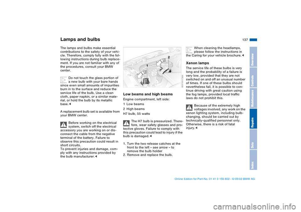
Low beams and high beamsEngine compartment, left side:
1Low beams
2High beams
H7 bulb, 55 watts
The H7 bulb is pressurized. There-
fore, wear safety glasses and pro-
tective gloves. Failure to comply with
this precaution could lead to injury if the
bulb is damaged.<
1. Turn the two release catches at the
front to the left – see arrow – to
remove the bulb holder
2. Remove and replace the bulb.
When cleaning the headlamps,
please follow the instructions in
the Caring for your vehicle brochure.<
Xenon lampsThe service life of these bulbs is very
long and the probability of a failure is
very low, provided that they are not
switched on and off an unusual number
of times. If one of these bulbs should
nevertheless fail, it is possible to con-
tinue driving with great caution using
the fog lamps, provided local traffic
laws do not prohibit this.
Because of the extremely high
voltages involved, any work on the
xenon lighting system, including bulb-
changing, should be carried out by
technically-qualified personnel only.
Otherwise, there is a risk of fatal
injury.<
OverviewControlsMaintenanceRepairsDataIndex
handbook.book Page 137 Saturday, July 27, 2002 1:36 PM
Page 139 of 166
139
Side turn signal indicators5 watt bulb
1. Use finger pressure against the rear
edge of the lamp – see arrow – to
press it forward for removal
2. Apply gentle pressure to the bulb
while turning it to the left to remove.
Tail lamps1Turn signal indicator
2Backup lamp
3Tail lamp
4Tail lamp/brake lamp
Tail lamp 4: 21/4 watt bulb
Remaining bulbs: 21 watts
Section of the left cargo area:
Bulbs in the fender:
All of the bulbs are integrated in a cen-
tral bulb holder.
1. Release and remove the cargo area
side panel
2. Release and remove the bulb holder
– see arrow
3. Remove the power plug and lay the
bulb holder to one side, for instance,
on the floor of the cargo area
4. Applying light pressure, turn the bulb
to the left. Remove and replace the
bulb
5. Plug in the power supply fitting
6. Press the bulb holder into position
until you hear it engage.
Lamps and bulbs
OverviewControlsMaintenanceRepairsDataIndex
handbook.book Page 139 Saturday, July 27, 2002 1:36 PM
Page 141 of 166

141
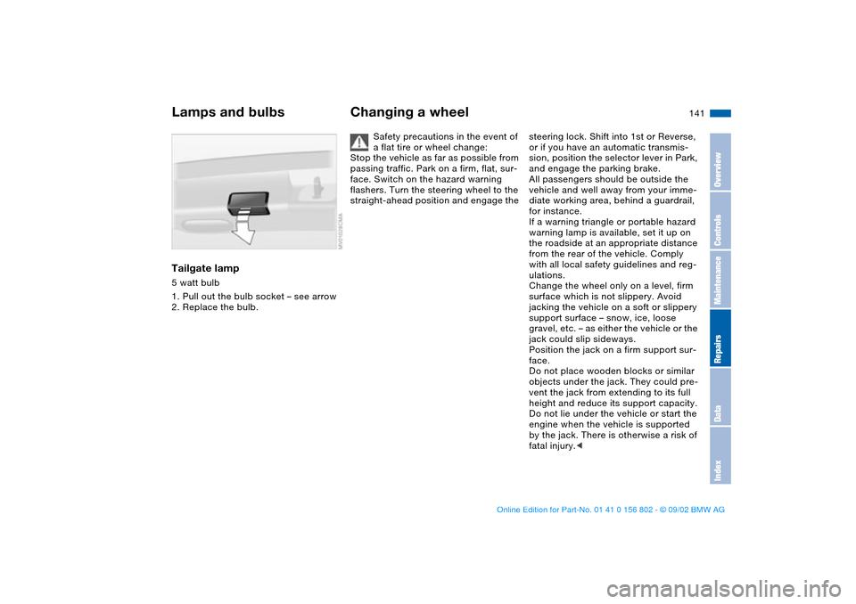
Tailgate lamp5 watt bulb
1. Pull out the bulb socket – see arrow
2. Replace the bulb.
Changing a wheel
Safety precautions in the event of
a flat tire or wheel change:
Stop the vehicle as far as possible from
passing traffic. Park on a firm, flat, sur-
face. Switch on the hazard warning
flashers. Turn the steering wheel to the
straight-ahead position and engage the
steering lock. Shift into 1st or Reverse,
or if you have an automatic transmis-
sion, position the selector lever in Park,
and engage the parking brake.
All passengers should be outside the
vehicle and well away from your imme-
diate working area, behind a guardrail,
for instance.
If a warning triangle or portable hazard
warning lamp is available, set it up on
the roadside at an appropriate distance
from the rear of the vehicle. Comply
with all local safety guidelines and reg-
ulations.
Change the wheel only on a level, firm
surface which is not slippery. Avoid
jacking the vehicle on a soft or slippery
support surface – snow, ice, loose
gravel, etc. – as either the vehicle or the
jack could slip sideways.
Position the jack on a firm support sur-
face.
Do not place wooden blocks or similar
objects under the jack. They could pre-
vent the jack from extending to its full
height and reduce its support capacity.
Do not lie under the vehicle or start the
engine when the vehicle is supported
by the jack. There is otherwise a risk of
fatal injury.<
Lamps and bulbs
OverviewControlsMaintenanceRepairsDataIndex
handbook.book Page 141 Saturday, July 27, 2002 1:36 PM
Page 143 of 166

143
wheel must be changed on a sur-
face with a more severe slope, take
additional precautions to secure
the vehicle from rolling
3. Wheels with full wheel covers*:
reach into the ventilation openings
and pull the cover off
4. Loosen the lug bolts by rotating
half a turn
5. Position the jack at the jacking
point – see arrows – closest to the
flat tire so that the jack base is ver-
tically below the jacking point and
the entire surface of the head of the
jack moves into the square recess
of the jacking point when the jack
is cranked – refer to the detail in the
next illustration
6. Jack the vehicle up until the wheel
you are changing is raised from the
ground
7. Unscrew the lug bolts and remove
the wheel
8. Remove accumulations of mud or
dirt from the mounting surfaces of
the wheel and hub. Clean the lug
bolts
9. Position the new wheel or the
space-saver spare tire on the hub
and screw at least two lug bolts fin-
ger-tight into opposite bolt holes
10. Screw in the remaining lug bolts.
Screw in all the bolts in a diagonal
pattern
11. Lower the jack and remove it from
beneath the vehicle
12. Tighten the lug bolts securely in a
diagonal pattern
Changing a wheel
OverviewControlsMaintenanceRepairsDataIndex
handbook.book Page 143 Saturday, July 27, 2002 1:36 PM