Page 66 of 178

66
LATCH child-restraint mounting
systemLATCH: Lower Anchors and Tethers for
CHildren
Canadian models only:
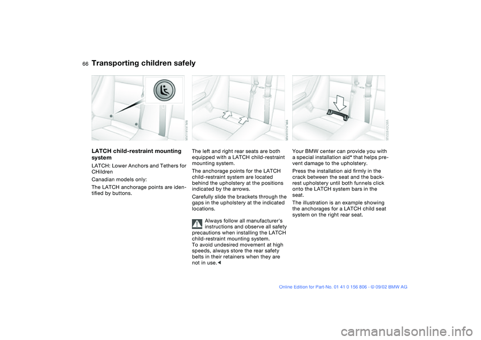
The LATCH anchorage points are iden-
tified by buttons.
The left and right rear seats are both
equipped with a LATCH child-restraint
mounting system.
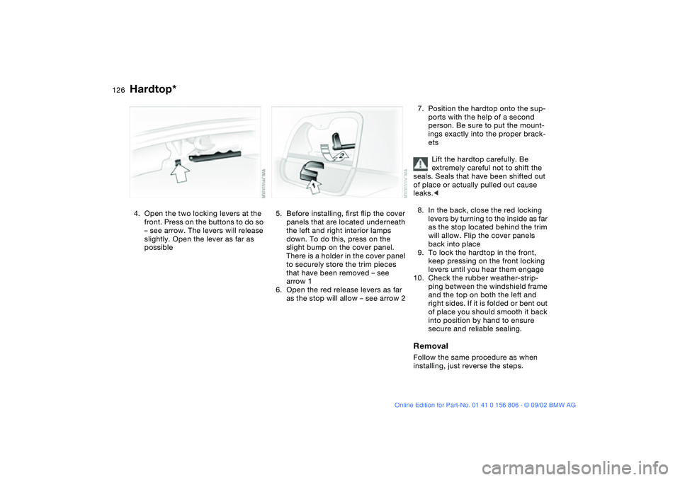
The anchorage points for the LATCH
child-restraint system are located
behind the upholstery at the positions
indicated by the arrows.
Carefully slide the brackets through the
gaps in the upholstery at the indicated
locations.
Always follow all manufacturer's
instructions and observe all safety
precautions when installing the LATCH
child-restraint mounting system.
To avoid undesired movement at high
speeds, always store the rear safety
belts in their retainers when they are
not in use.<
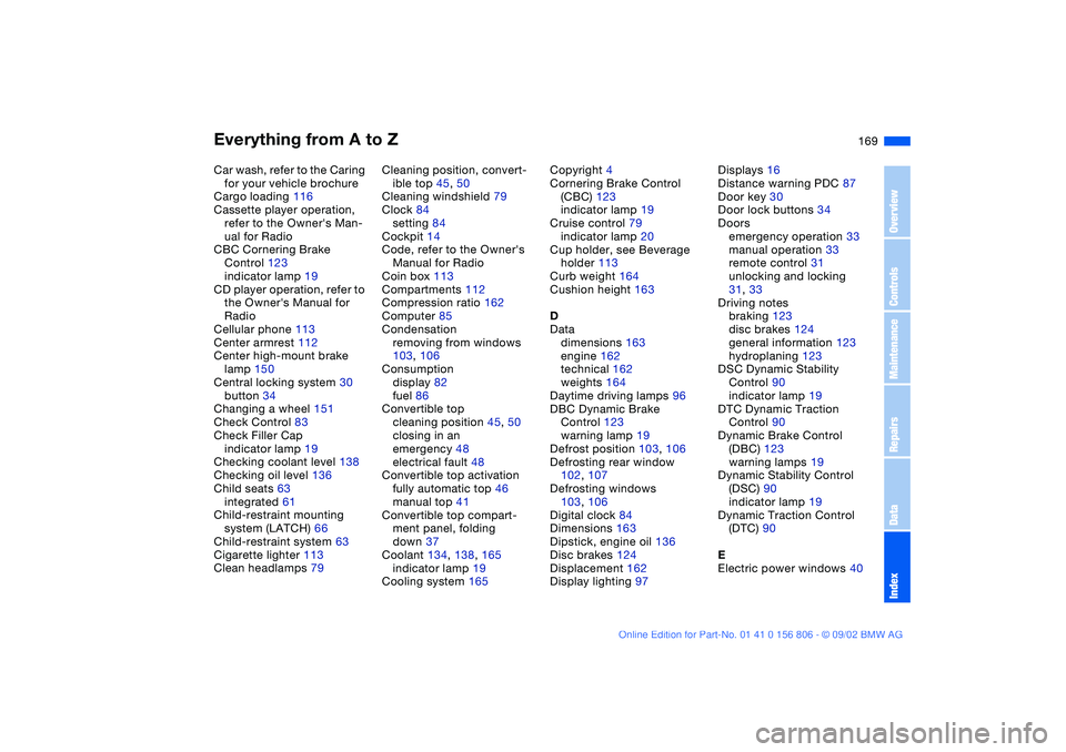
Your BMW center can provide you with
a special installation aid* that helps pre-
vent damage to the upholstery.
Press the installation aid firmly in the
crack between the seat and the back-
rest upholstery until both funnels click
onto the LATCH system bars in the
seat.
The illustration is an example showing
the anchorages for a LATCH child seat
system on the right rear seat.
Transporting children safely
handbook.book Page 66 Wednesday, July 31, 2002 9:29 AM
Page 126 of 178

126
4. Open the two locking levers at the
front. Press on the buttons to do so
– see arrow. The levers will release
slightly. Open the lever as far as
possible
5. Before installing, first flip the cover
panels that are located underneath
the left and right interior lamps
down. To do this, press on the
slight bump on the cover panel.
There is a holder in the cover panel
to securely store the trim pieces
that have been removed – see
arrow 1
6. Open the red release levers as far
as the stop will allow – see arrow 2
7. Position the hardtop onto the sup-
ports with the help of a second
person. Be sure to put the mount-
ings exactly into the proper brack-
ets
Lift the hardtop carefully. Be
extremely careful not to shift the
seals. Seals that have been shifted out
of place or actually pulled out cause
leaks.<
8. In the back, close the red locking
levers by turning to the inside as far
as the stop located behind the trim
will allow. Flip the cover panels
back into place
9. To lock the hardtop in the front,
keep pressing on the front locking
levers until you hear them engage
10. Check the rubber weather-strip-
ping between the windshield frame
and the top on both the left and
right sides. If it is folded or bent out
of place you should smooth it back
into position by hand to ensure
secure and reliable sealing.RemovalFollow the same procedure as when
installing, just reverse the steps.
Hardtop*
handbook.book Page 126 Wednesday, July 31, 2002 9:29 AM
Page 169 of 178

Everything from A to Z
169
Car wash, refer to the Caring
for your vehicle brochure
Cargo loading 116
Cassette player operation,
refer to the Owner's Man-
ual for Radio
CBC Cornering Brake
Control 123
indicator lamp 19
CD player operation, refer to
the Owner's Manual for
Radio
Cellular phone 113
Center armrest 112
Center high-mount brake
lamp 150
Central locking system 30
button 34
Changing a wheel 151
Check Control 83
Check Filler Cap
indicator lamp 19
Checking coolant level 138
Checking oil level 136
Child seats 63
integrated 61
Child-restraint mounting
system (LATCH) 66
Child-restraint system 63
Cigarette lighter 113
Clean headlamps 79Cleaning position, convert-
ible top 45, 50
Cleaning windshield 79
Clock 84
setting 84
Cockpit 14
Code, refer to the Owner's
Manual for Radio
Coin box 113
Compartments 112
Compression ratio 162
Computer 85
Condensation
removing from windows
103, 106
Consumption
display 82
fuel 86
Convertible top
cleaning position 45, 50
closing in an
emergency 48
electrical fault 48
Convertible top activation
fully automatic top 46
manual top 41
Convertible top compart-
ment panel, folding
down 37
Coolant 134, 138, 165
indicator lamp 19
Cooling system 165Copyright 4
Cornering Brake Control
(CBC) 123
indicator lamp 19
Cruise control 79
indicator lamp 20
Cup holder, see Beverage
holder 113
Curb weight 164
Cushion height 163
D
Data
dimensions 163
engine 162
technical 162
weights 164
Daytime driving lamps 96
DBC Dynamic Brake
Control 123
warning lamp 19
Defrost position 103, 106
Defrosting rear window
102, 107
Defrosting windows
103, 106
Digital clock 84
Dimensions 163
Dipstick, engine oil 136
Disc brakes 124
Displacement 162
Display lighting 97Displays 16
Distance warning PDC 87
Door key 30
Door lock buttons 34
Doors
emergency operation 33
manual operation 33
remote control 31
unlocking and locking
31, 33
Driving notes
braking 123
disc brakes 124
general information 123
hydroplaning 123
DSC Dynamic Stability
Control 90
indicator lamp 19
DTC Dynamic Traction
Control 90
Dynamic Brake Control
(DBC) 123
warning lamps 19
Dynamic Stability Control
(DSC) 90
indicator lamp 19
Dynamic Traction Control
(DTC) 90
E
Electric power windows 40
OverviewControlsMaintenanceRepairsDataIndex
handbook.book Page 169 Wednesday, July 31, 2002 9:29 AM
Page 172 of 178

Everything from A to ZOil additives 137
Oil change intervals, refer to
the Service and Warranty
Information Booklet for US
models/Warranty and Ser-
vice Guide Booklet for
Canadian models
Oil consumption 136
Oil dipstick 136
Oil filter change 165
Oil level
checking 136
indicator lamp 19
warning lamp 18
Oil pressure
warning lamp 18
OIL SERVICE 83
Oil types 137
Onboard computer, refer to
the Owner's Manual for
Onboard Computer
Onboard tool kit 146
Opening and closing
from the inside 34
via the door lock 33
via the remote control 31
Operating elements 14
Outlets, ventilation 104
Outside temperature dis-
play 85P
Panic mode, trigger alarm
32
Park Distance Control
(PDC) 87
Parking aid 87
Parking brake 72
Parking lamps 96
replacing bulb 148
PDC Park Distance
Control 87
Pocket flashlight 109
Pollen 103, 108
Power output 162
Power seat 53
Pressure, tires 25, 92, 127
monitoring 92
R
Radiator 165
Radio, refer to the Owner's
Manual for Radio
Rain sensor 78
Range 86
Reading lamps
front 98
rear 98
Rear lamps 149
Rear window defroster
102, 107
Rearview mirror 59Recirculated-air mode
102, 107
Refueling 24
Remote control 31
Remote control keys 30
Replacement key 30, 31
Reporting safety defects 6
Reserve indicator lamp 82
Restraint system 63
Reverse 73
Rims 130
Rollover protection
system 67
indicator lamp 19
lowering 67
Roof load capacity 164
Roof-mounted luggage rack
118, 125
Run Flat tires 129, 155
S
Safe seating position 52
Safety belts 56
seat-integrated safety belt
system (SGS) 55
Seat
rear entry aid 55
Seat adjustment 52
lumbar support 53
thigh support 53
Seat heating 58
Seat memory 57Securing cargo 116
Securing child-restraint sys-
tem 65
Securing devices 117
Selector lever, automatic
transmission 74
Service and Warranty Infor-
mation Booklet 140
Service Engine Soon
warning lamp 19
Service interval display
83, 140
Setting
clock 84
Shiftlock 74
Side airbags 61
Side turn signal indicators
replacing bulb 149
Size 163
Ski bag 115
Snow chains 131
Socket 114
Spare key 30
Spare tire 151
Speedometer 16
Standing lamps 97
Starting problems 70
Starting the engine 70
Steering wheel lock 70
Steering wheel with multi-
function buttons 22
Steering wheel, adjusting 59
handbook.book Page 172 Wednesday, July 31, 2002 9:29 AM