2003 AUDI A8 roof
[x] Cancel search: roofPage 7 of 96
Downloaded from www.Manualslib.com manuals search engine 7
Body
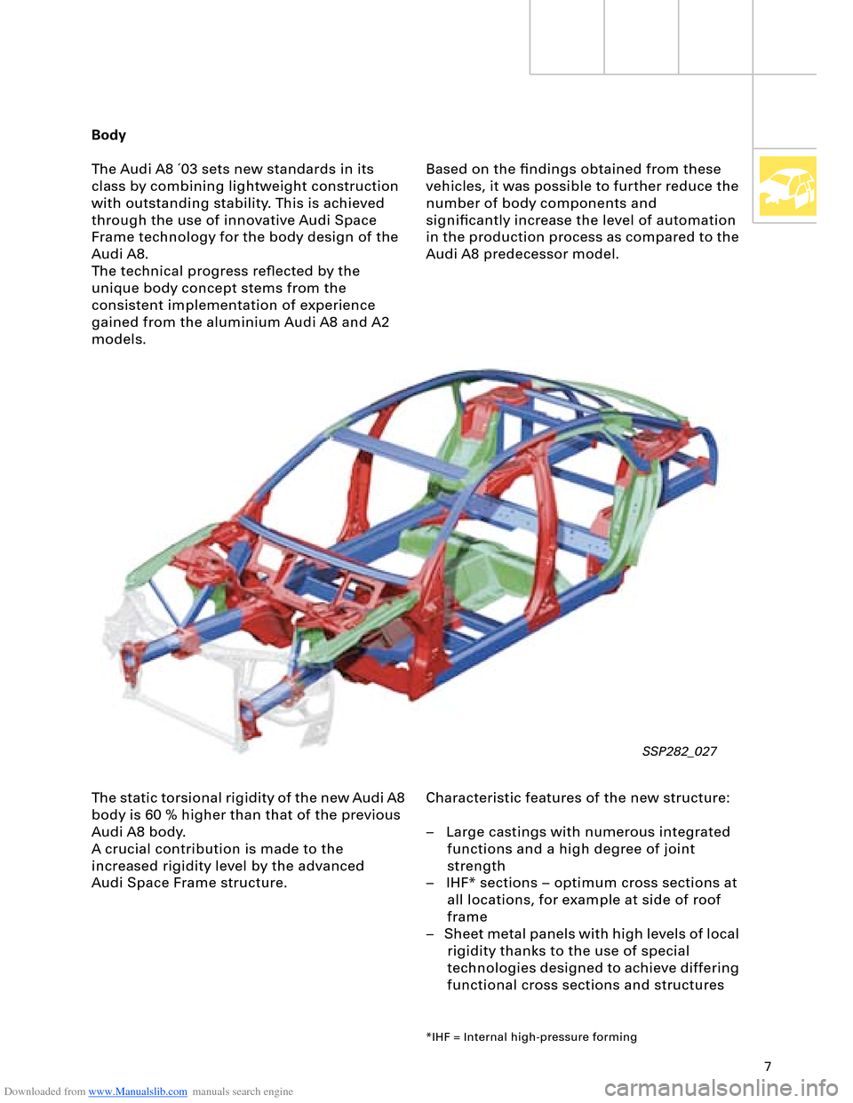
The Audi A8 ´03 sets new standards in its
class by combining lightweight construction
with outstanding stability. This is achieved
through the use of innovative Audi Space
Frame technology for the body design of the
Audi A8.
The technical progress reflected by the
unique body concept stems from the
consistent implementation of experience
gained from the aluminium Audi A8 and A2
models.
SSP282_027
Based on the findings obtained from these
vehicles, it was possible to further reduce the
number of body components and
significantly increase the level of automation
in the production process as compared to the
Audi A8 predecessor model.
The static torsional rigidity of the new Audi A8
body is 60 % higher than that of the previous
Audi A8 body.
A crucial contribution is made to the
increased rigidity level by the advanced
Audi Space Frame structure.Characteristic features of the new structure:
– Large castings with numerous integrated
functions and a high degree of joint
strength
– IHF* sections – optimum cross sections at
all locations, for example at side of roof
frame
– Sheet metal panels with high levels of local
rigidity thanks to the use of special
technologies designed to achieve differing
functional cross sections and structures
*IHF = Internal high-pressure forming
Page 8 of 96
Downloaded from www.Manualslib.com manuals search engine 8
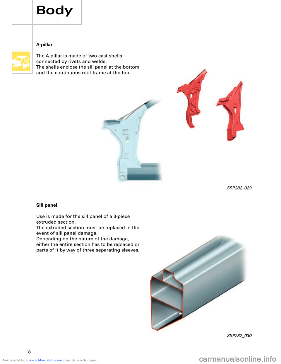
A-pillar
The A-pillar is made of two cast shells
connected by rivets and welds.
The shells enclose the sill panel at the bottom
and the continuous roof frame at the top.
SSP282_029
Sill panel
Use is made for the sill panel of a 3-piece
extruded section.
The extruded section must be replaced in the
event of sill panel damage.
Depending on the nature of the damage,
either the entire section has to be replaced or
parts of it by way of three separating sleeves.
Body
SSP282_030
Page 9 of 96
Downloaded from www.Manualslib.com manuals search engine 9
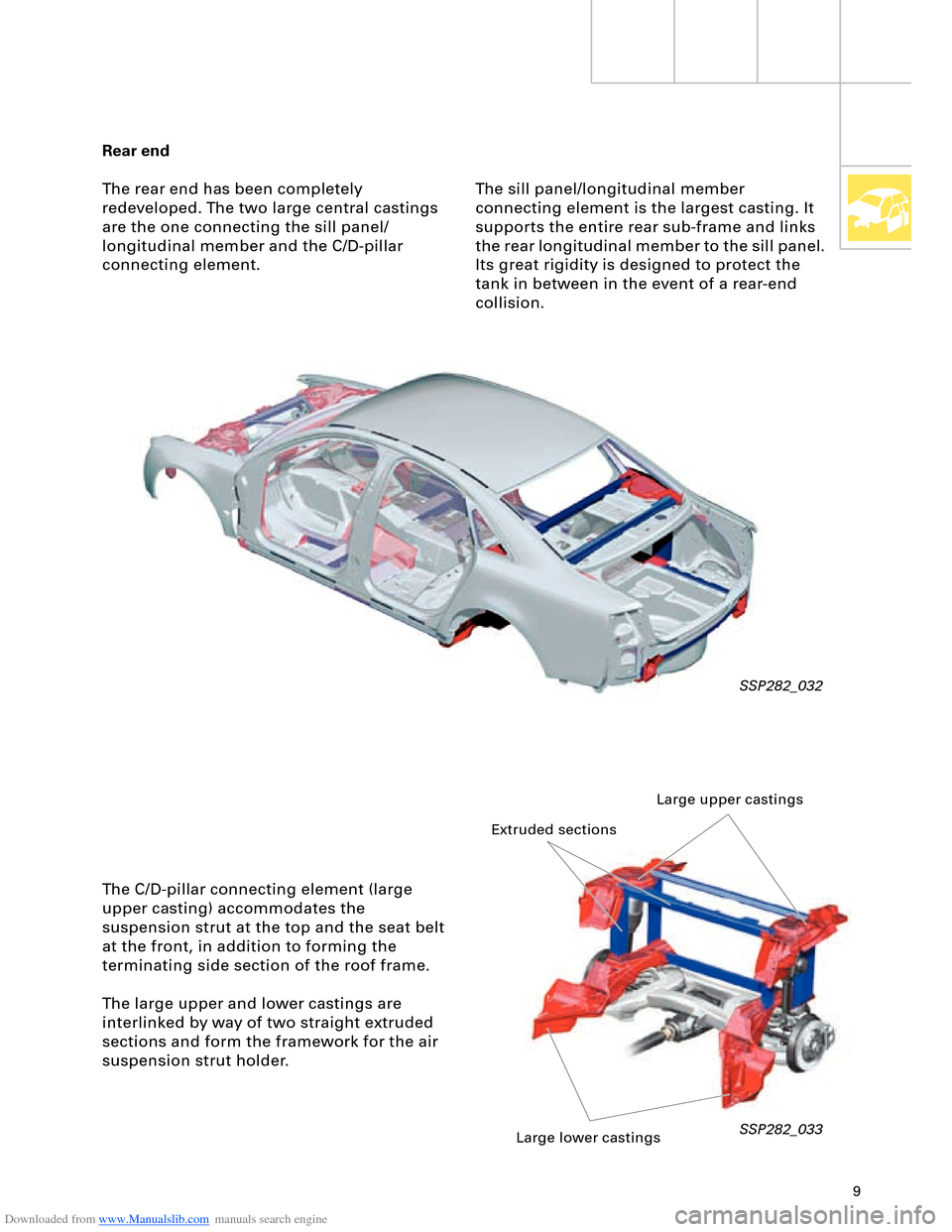
Rear end
The rear end has been completely
redeveloped. The two large central castings
are the one connecting the sill panel/
longitudinal member and the C/D-pillar
connecting element.
SSP282_032
The C/D-pillar connecting element (large
upper casting) accommodates the
suspension strut at the top and the seat belt
at the front, in addition to forming the
terminating side section of the roof frame.
The large upper and lower castings are
interlinked by way of two straight extruded
sections and form the framework for the air
suspension strut holder.
SSP282_033
The sill panel/longitudinal member
connecting element is the largest casting. It
supports the entire rear sub-frame and links
the rear longitudinal member to the sill panel.
Its great rigidity is designed to protect the
tank in between in the event of a rear-end
collision.
Large upper castings
Extruded sections
Large lower castings
Page 59 of 96
Downloaded from www.Manualslib.com manuals search engine 59SSP282_063
Telephone/
telematics control
unit J526
Front information
display and operating
unit control unit J523Rear DVD changer
R162Telephone
handset
R37
Control unit for rear
left
information display
and operating
unit J648
DSP control unit
J525
Navigation system
control unit
J401
TV tuner
R78
Digital radio
R147
Radio module R Chip card reader
control unit
J676 CD changer
R41 CD ROM drive
R92 Data bus diagnostic
interface J533
Fresh-air blower
control unit
J126Heated windscreen
control unit J505Rear left footwell
heater element Z42Rear right footwell
heater element Z43Driver seat
ventilation
control unit J672Front passenger
seat ventilation
control unit J673
Parking aid control
unit J446 Entry and start
authorisation
control unit J518 Energy
management
control unit J644 Rear seat
adjustment with
memory control
unit J522 Climatronic control
unit J255
Trailer detector
control unit J345
Rear Climatronic
control and
display unit E265Tyre pressure
monitor control unit
J502
Sun roof electronics
control unit J528
Additional heater
control unit J364Driver identification
control unit J589
Auxiliary heating
radio controlled
receiver R64 Sliding sun roof
motor V1 Front passenger
side rear seat
ventilation
control unit J675 Driver side rear seat
ventilation control
unit J674 Control unit for rear
right
information display
and operating
unit J649
MOST busBluetooth
TM
LIN
LIN
Page 60 of 96
Downloaded from www.Manualslib.com manuals search engine 60
LOCAL INTERCONNECT NETWORK
Electrical System
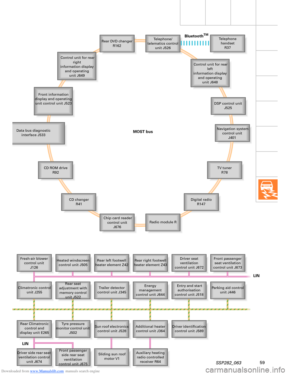
The familiar CAN bus (two-wire bus) is
supplemented by the following bus systems:
– LIN bus (single-wire data bus)
– MOST bus (optical data bus)
– Bluetooth
TM (wireless data bus)
LIN bus
LIN stands for Local Interconnect Network.
Local Interconnect means that all control
units are located within a limited structural
space (e.g. roof). This is also referred to as
"local sub-system".
Data are exchanged between the individual
LIN bus systems in a vehicle by one control
unit in each case using the CAN data bus.
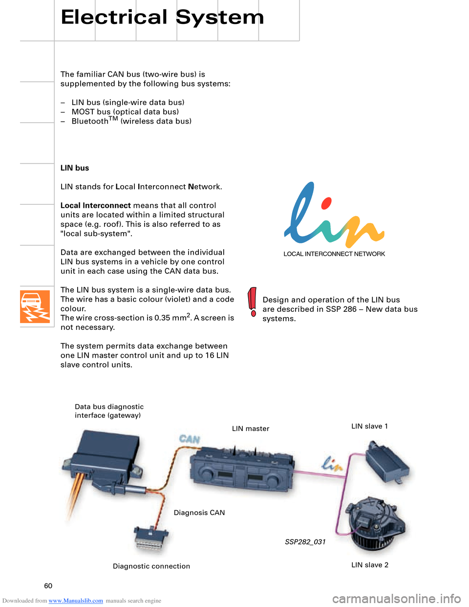
The LIN bus system is a single-wire data bus.
The wire has a basic colour (violet) and a code
colour.
The wire cross-section is 0.35 mm
2. A screen is
not necessary.
The system permits data exchange between
one LIN master control unit and up to 16 LIN
slave control units.
SSP282_031
Design and operation of the LIN bus
are described in SSP 286 – New data bus
systems.
Diagnostic connection Data bus diagnostic
interface (gateway)
LIN master
LIN slave 2 LIN slave 1
Diagnosis CAN
Page 63 of 96
Downloaded from www.Manualslib.com manuals search engine 63
Vehicle electrical system
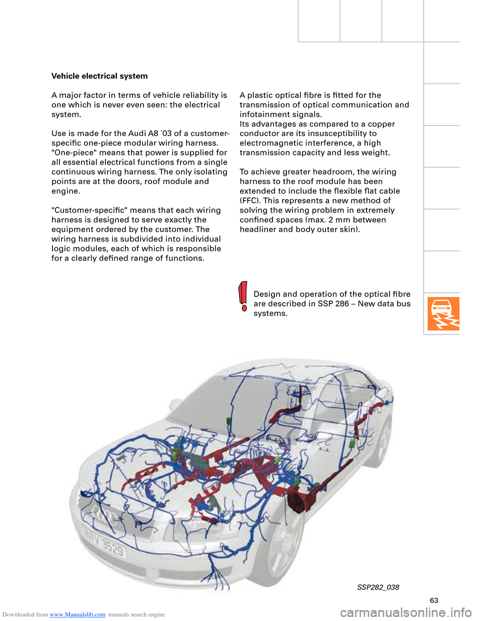
A major factor in terms of vehicle reliability is
one which is never even seen: the electrical
system.
Use is made for the Audi A8 ´03 of a customer-
specific one-piece modular wiring harness.
"One-piece" means that power is supplied for
all essential electrical functions from a single
continuous wiring harness. The only isolating
points are at the doors, roof module and
engine.
"Customer-specific" means that each wiring
harness is designed to serve exactly the
equipment ordered by the customer. The
wiring harness is subdivided into individual
logic modules, each of which is responsible
for a clearly defined range of functions.
SSP282_038
Design and operation of the optical fibre
are described in SSP 286 – New data bus
systems. A plastic optical fibre is fitted for the
transmission of optical communication and
infotainment signals.
Its advantages as compared to a copper
conductor are its insusceptibility to
electromagnetic interference, a high
transmission capacity and less weight.
To achieve greater headroom, the wiring
harness to the roof module has been
extended to include the flexible flat cable
(FFC). This represents a new method of
solving the wiring problem in extremely
confined spaces (max. 2 mm between
headliner and body outer skin).
Page 80 of 96
Downloaded from www.Manualslib.com manuals search engine 80
Heating/Air Conditioner
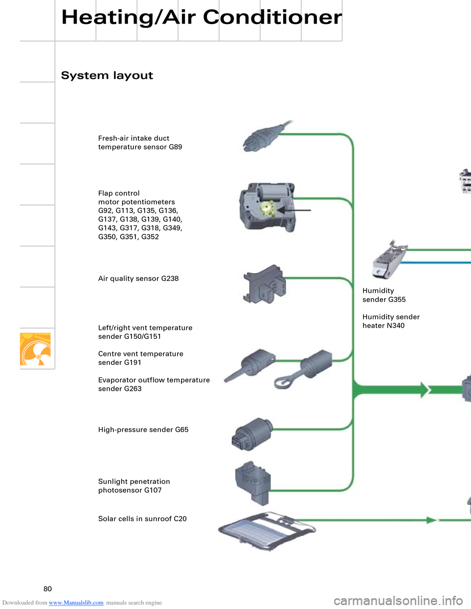
SSP282_103 Fresh-air intake duct
temperature sensor G89
Flap control
motor potentiometers
G92, G113, G135, G136,
G137, G138, G139, G140,
G143, G317, G318, G349,
G350, G351, G352
Air quality sensor G238
Left/right vent temperature
sender G150/G151
Centre vent temperature
sender G191
Evaporator outflow temperature
sender G263
High-pressure sender G65
Sunlight penetration
photosensor G107
Solar cells in sunroof C20
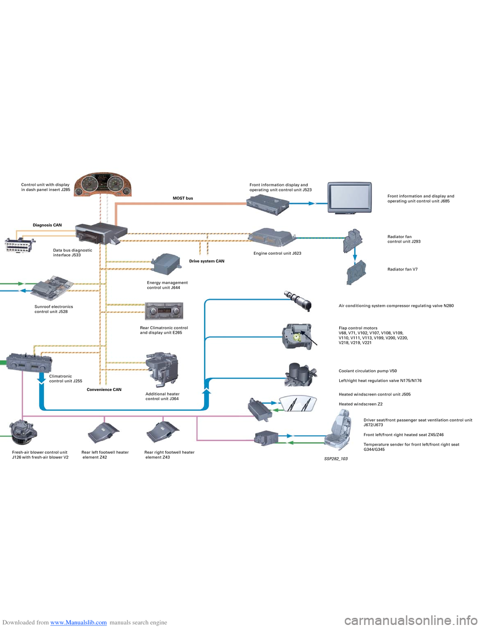
System layoutControl unit with display
in dash panel insert J285
MOST busFront information display and
operating unit control unit J523
Rear right footwell heater
element Z43 Rear left footwell heater
element Z42 Fresh-air blower control unit
J126 with fresh-air blower V2Diagnosis CAN
Data bus diagnostic
interface J533
Sunroof electronics
control unit J528 Humidity
sender G355
Humidity sender
heater N340
Climatronic
control unit J255
Convenience CAN
Additional heater
control unit J364 Rear Climatronic control
and display unit E265Energy management
control unit J644Drive system CANEngine control unit J623Front information and display and
operating unit control unit J685
Radiator fan
control unit J293
Radiator fan V7
Air conditioning system compressor regulating valve N280
Flap control motors
V68, V71, V102, V107, V108, V109,
V110, V111, V113, V199, V200, V220,
V218, V219, V221
Coolant circulation pump V50
Left/right heat regulation valve N175/N176
Heated windscreen control unit J505
Heated windscreen Z2
Driver seat/front passenger seat ventilation control unit
J672/J673
Front left/front right heated seat Z45/Z46
Temperature sender for front left/front right seat
G344/G345
Page 81 of 96
Downloaded from www.Manualslib.com manuals search engine 80
Heating/Air Conditioner
SSP282_103 Fresh-air intake duct
temperature sensor G89
Flap control
motor potentiometers
G92, G113, G135, G136,
G137, G138, G139, G140,
G143, G317, G318, G349,
G350, G351, G352
Air quality sensor G238
Left/right vent temperature
sender G150/G151
Centre vent temperature
sender G191
Evaporator outflow temperature
sender G263
High-pressure sender G65
Sunlight penetration
photosensor G107
Solar cells in sunroof C20
System layoutControl unit with display
in dash panel insert J285
MOST busFront information display and
operating unit control unit J523
Rear right footwell heater
element Z43 Rear left footwell heater
element Z42 Fresh-air blower control unit
J126 with fresh-air blower V2Diagnosis CAN
Data bus diagnostic
interface J533
Sunroof electronics
control unit J528 Humidity
sender G355
Humidity sender
heater N340
Climatronic
control unit J255
Convenience CAN
Additional heater
control unit J364 Rear Climatronic control
and display unit E265Energy management
control unit J644Drive system CANEngine control unit J623Front information and display and
operating unit control unit J685
Radiator fan
control unit J293
Radiator fan V7
Air conditioning system compressor regulating valve N280
Flap control motors
V68, V71, V102, V107, V108, V109,
V110, V111, V113, V199, V200, V220,
V218, V219, V221
Coolant circulation pump V50
Left/right heat regulation valve N175/N176
Heated windscreen control unit J505
Heated windscreen Z2
Driver seat/front passenger seat ventilation control unit
J672/J673
Front left/front right heated seat Z45/Z46
Temperature sender for front left/front right seat
G344/G345