Page 32 of 96
Downloaded from www.Manualslib.com manuals search engine 32
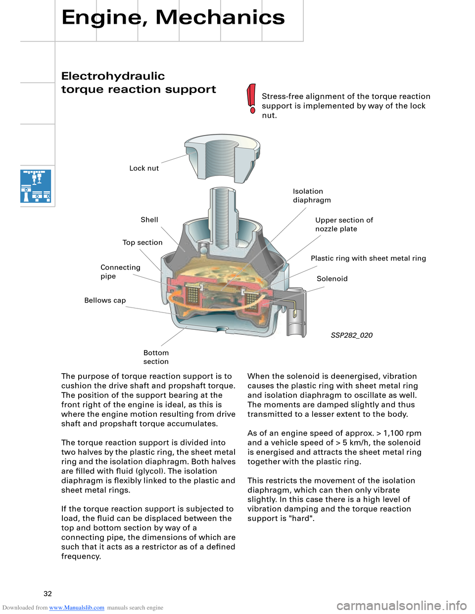
Electrohydraulic
torque reaction support
Engine, Mechanics
When the solenoid is deenergised, vibration
causes the plastic ring with sheet metal ring
and isolation diaphragm to oscillate as well.
The moments are damped slightly and thus
transmitted to a lesser extent to the body.
As of an engine speed of approx. > 1,100 rpm
and a vehicle speed of > 5 km/h, the solenoid
is energised and attracts the sheet metal ring
together with the plastic ring.
This restricts the movement of the isolation
diaphragm, which can then only vibrate
slightly. In this case there is a high level of
vibration damping and the torque reaction
support is "hard". The purpose of torque reaction support is to
cushion the drive shaft and propshaft torque.
The position of the support bearing at the
front right of the engine is ideal, as this is
where the engine motion resulting from drive
shaft and propshaft torque accumulates.
The torque reaction support is divided into
two halves by the plastic ring, the sheet metal
ring and the isolation diaphragm. Both halves
are filled with fluid (glycol). The isolation
diaphragm is flexibly linked to the plastic and
sheet metal rings.
If the torque reaction support is subjected to
load, the fluid can be displaced between the
top and bottom section by way of a
connecting pipe, the dimensions of which are
such that it acts as a restrictor as of a defined
frequency.
SSP282_020
Stress-free alignment of the torque reaction
support is implemented by way of the lock
nut.
Lock nut
Shell
Bellows cap
Bottom
sectionIsolation
diaphragm
Plastic ring with sheet metal ringUpper section of
nozzle plate
Solenoid Connecting
pipeTop section
Page 41 of 96
Downloaded from www.Manualslib.com manuals search engine 41
Automatically controlled
starting
The automatic start control is integrated into
the engine control unit.
A new feature is that starter control is no
longer implemented by way of the ignition/
starter switch D (switching of terminal 50),
but rather it is performed automatically by
the engine control unit.
Release for starter actuation is always
transmitted by the entry and start
authorisation control unit J518 to the engine
control unit J623.
In addition to general release by the
immobilizer, the following start release
conditions also have to be satisfied:
– Start signal from entry and start
authorisation switch E415 or entry and
start authorisation button E408
– Clutch pedal pressed, signal from clutch
pedal switch F194 (manual gearbox only)
– Selector lever position P or N (automatic
gearbox control unit J217)
– In the event of start signal via entry and
start authorisation button E408, brake
must be pressed (signal from brake light
switch F via separate interface)
As a safeguard, P/N signal or signal from
clutch pedal switch F194 must be applied
to the separate interfaces of the two
control units (J623 and J518).
Additional safeguard, as entry and start
authorisation button E408 can be
actuated by front passenger.
1
2 1
1
2
Page 43 of 96
Downloaded from www.Manualslib.com manuals search engine 43
D1
30
15
J329J53J695J694
75xE415
N376
6x
J623
J518
50R
50R
3
12
12
E408
STOP START
58s
210 210
D1 Inhibitor reading unit
E408 Entry and start authorisation button
E415 Entry and start authorisation switch
J53 Starter motor relay
J329 Terminal 15 voltage supply relay
J518 Entry and start authorisation
control unit Block diagram
SSP282_024
Colour code
= Input signal
= Output signal
= Positive supply
= Earth
J623 Engine control unit
J694 Terminal 75x voltage supply relay
J695 Starter relay 2
N376 Ignition key withdrawal lock magnet
Additional signals
F - Brake light switch
Manual gearbox -> F194
Clutch pedal switch
Automatic gearbox -> Selector lever
position from automatic gearbox
control unit J217
Terminal 50/starter
1
2
3
Page 46 of 96
Downloaded from www.Manualslib.com manuals search engine 46
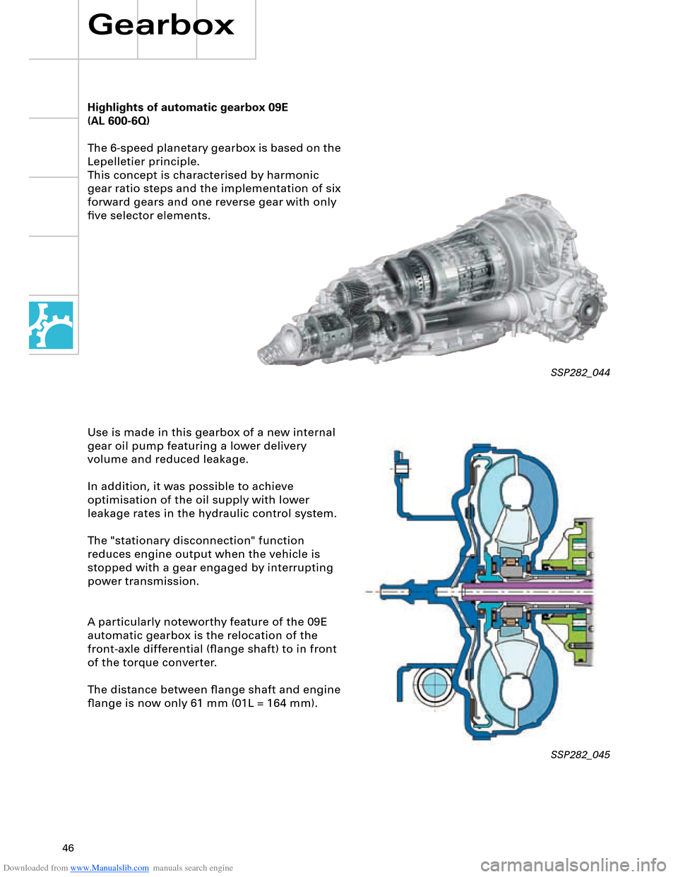
Highlights of automatic gearbox 09E
The 6-speed planetary gearbox is based on the
Lepelletier principle.
This concept is characterised by harmonic
gear ratio steps and the implementation of six
forward gears and one reverse gear with only
five selector elements.
Use is made in this gearbox of a new internal
gear oil pump featuring a lower delivery
volume and reduced leakage.
In addition, it was possible to achieve
optimisation of the oil supply with lower
leakage rates in the hydraulic control system.
The "stationary disconnection" function
reduces engine output when the vehicle is
stopped with a gear engaged by interrupting
power transmission.
A particularly noteworthy feature of the 09E
automatic gearbox is the relocation of the
front-axle differential (flange shaft) to in front
of the torque converter.
The distance between flange shaft and engine
flange is now only 61 mm (01L = 164 mm).
Gearbox
SSP282_044
SSP282_045
(AL 600-6Q)
Page 49 of 96
Downloaded from www.Manualslib.com manuals search engine 49
All axle components are new on account of
the geometric and kinematic modifications as
compared to the predecessor model, the air
suspension and the weight reductions
achieved.
Front axle
The familiar four-link front axle was retained
for the Audi A8 '03.
A significant new feature is the air
suspension in combination with
electronically controlled dampers (refer to
Section on air suspension).
Front axle highlights
– Subframe
– Auxiliary frame
– Anti-roll bar
– Wheel bearing housing
– Wheel bearing with wheel speed sensing
– Mounting bracket for damper unit
Front axle design and operation are
described in SSP 285.
SSP282_050
Running Gear
Page 50 of 96
Downloaded from www.Manualslib.com manuals search engine 50
All axle components are new on account of
the geometric and kinematic modifications as
compared to the predecessor model, the air
suspension and the weight reductions
achieved.
Rear axle highlights
– Use of air suspension in conjunction with
electronically controlled damping
– Aluminium subframe to help
reduce weight
– Connection of anti-roll bar to trapezium
link
– Use of shorter track rod to reduce change
in toe on compression and extension of
suspension
– Use of ball studs to connect wheel bearing
housing and track rod, thus reducing
secondary spring rate
– Use of slotted bonded rubber bushes in
upper transverse link and connection
between trapezium link and subframe
Rear axle design and operation are
described in SSP 285.
Rear axle
The rear axle is a more advanced version of
the familiar Audi A8 trapezium-link axle.
Running Gear
SSP282_051
Page 58 of 96
Downloaded from www.Manualslib.com manuals search engine 58
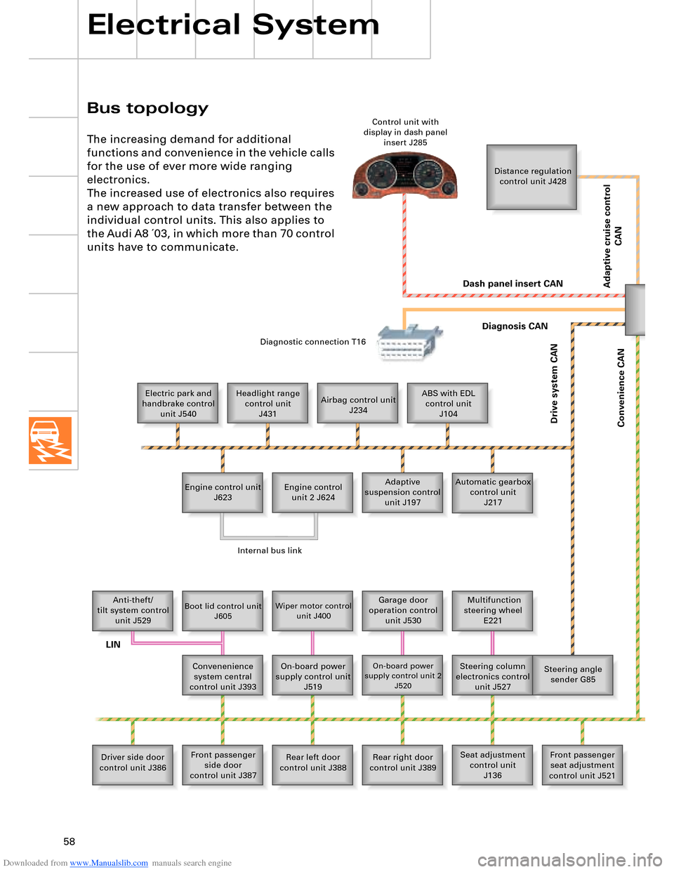
Bus topology
Electrical System
The increasing demand for additional
functions and convenience in the vehicle calls
for the use of ever more wide ranging
electronics.
The increased use of electronics also requires
a new approach to data transfer between the
individual control units. This also applies to
the Audi A8 ´03, in which more than 70 control
units have to communicate.
Distance regulation
control unit J428
Electric park and
handbrake control
unit J540Headlight range
control unit
J431Airbag control unit
J234ABS with EDL
control unit
J104
Engine control unit
J623Adaptive
suspension control
unit J197 Engine control
unit 2 J624Automatic gearbox
control unit
J217
Anti-theft/
tilt system control
unit J529
Boot lid control unit
J605Wiper motor control
unit J400Garage door
operation control
unit J530 Multifunction
steering wheel
E221
Convenenience
system central
control unit J393On-board power
supply control unit
J519
On-board power
supply control unit 2
J520Steering column
electronics control
unit J527Steering angle
sender G85
Driver side door
control unit J386Front passenger
side door
control unit J387Rear left door
control unit J388Rear right door
control unit J389Seat adjustment
control unit
J136Front passenger
seat adjustment
control unit J521 Control unit with
display in dash panel
insert J285
Diagnostic connection T16
Dash panel insert CAN
Drive system CAN
Diagnosis CAN
Convenience CAN
Internal bus link
LIN
Adaptive cruise control
CAN
Page 68 of 96
Downloaded from www.Manualslib.com manuals search engine 68
Electrical System
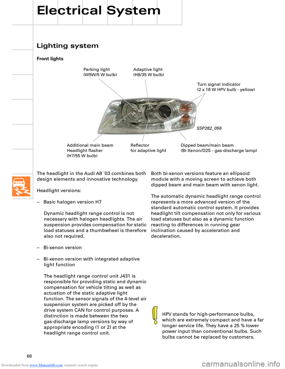
The headlight in the Audi A8 ´03 combines both
design elements and innovative technology.
Headlight versions:
– Basic halogen version H7
Dynamic headlight range control is not
necessary with halogen headlights. The air
suspension provides compensation for static
load statuses and a thumbwheel is therefore
also not required.
– Bi-xenon version
– Bi-xenon version with integrated adaptive
light function
The headlight range control unit J431 is
responsible for providing static and dynamic
compensation for vehicle tilting as well as
actuation of the static adaptive light
function. The sensor signals of the 4-level air
suspension system are picked off by the
drive system CAN for control purposes. A
distinction is made between the two
gas-discharge lamp versions by way of
appropriate encoding (1 or 2) at the
headlight range control unit.
Lighting system
Front lights
SSP282_056
HPV stands for high-performance bulbs,
which are extremely compact and have a far
longer service life. They have a 25 % lower
power input than conventional bulbs. Such
bulbs cannot be replaced by customers.
Both bi-xenon versions feature an ellipsoid
module with a moving screen to achieve both
dipped beam and main beam with xenon light.
The automatic dynamic headlight range control
represents a more advanced version of the
standard automatic control system. It provides
headlight tilt compensation not only for various
load statuses but also as a dynamic function
reacting to differences in running gear
inclination caused by acceleration and
deceleration.
Dipped beam/main beam
(Bi-Xenon/D2S - gas-discharge lamp)Turn signal indicator
(2 x 16 W HPV bulb - yellow) Parking light
(W5W/5 W bulb)Adaptive light
(H8/35 W bulb)
Additional main beam
Headlight flasher
(H7/55 W bulb)Reflector
for adaptive light