Page 33 of 96
Downloaded from www.Manualslib.com manuals search engine 33
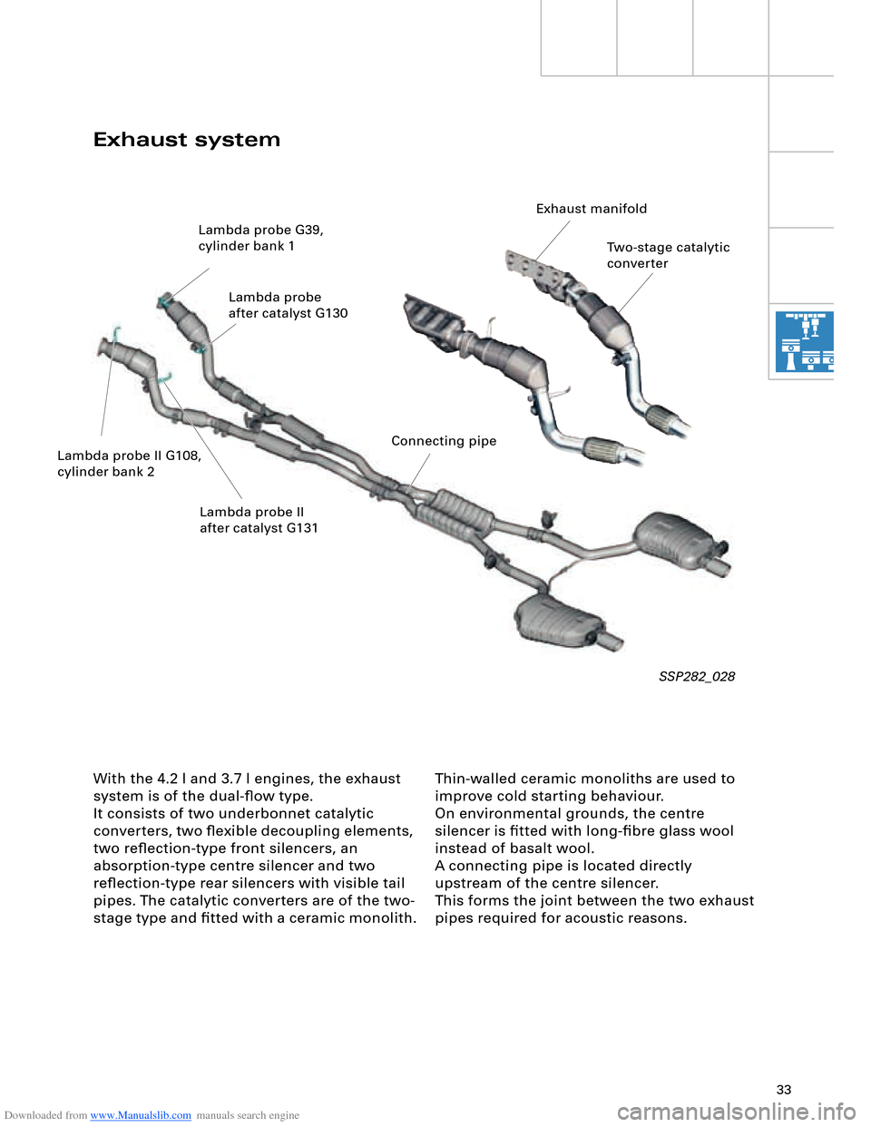
Thin-walled ceramic monoliths are used to
improve cold starting behaviour.
On environmental grounds, the centre
silencer is fitted with long-fibre glass wool
instead of basalt wool.
A connecting pipe is located directly
upstream of the centre silencer.
This forms the joint between the two exhaust
pipes required for acoustic reasons.
With the 4.2 l and 3.7 l engines, the exhaust
system is of the dual-flow type.
It consists of two underbonnet catalytic
converters, two flexible decoupling elements,
two reflection-type front silencers, an
absorption-type centre silencer and two
reflection-type rear silencers with visible tail
pipes. The catalytic converters are of the two-
stage type and fitted with a ceramic monolith.
SSP282_028
Exhaust system
Two-stage catalytic
converter
Lambda probe G39,
cylinder bank 1
Lambda probe
after catalyst G130
Lambda probe II G108,
cylinder bank 2 Lambda probe II
after catalyst G131 Exhaust manifold
Connecting pipe
Page 34 of 96
Downloaded from www.Manualslib.com manuals search engine 34
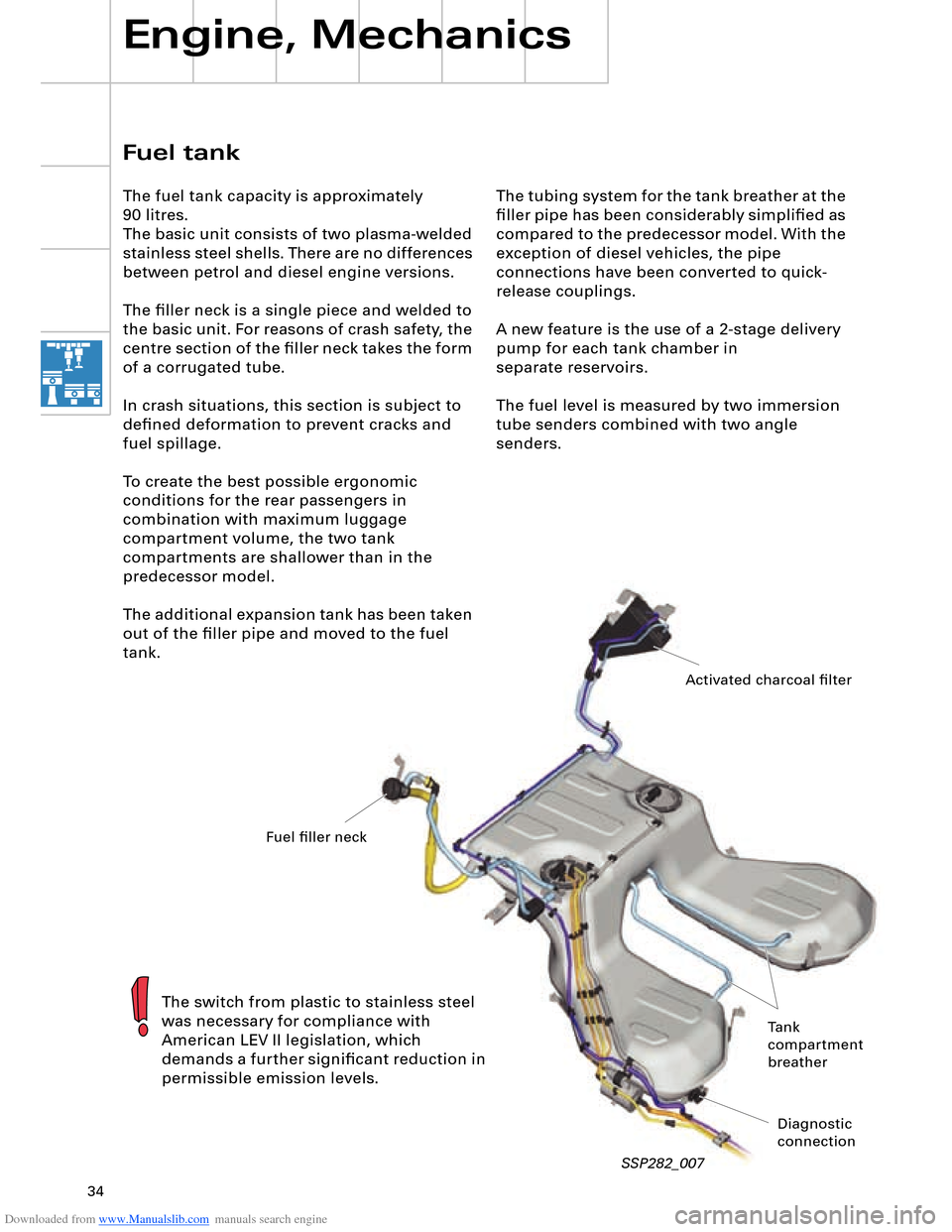
The tubing system for the tank breather at the
filler pipe has been considerably simplified as
compared to the predecessor model. With the
exception of diesel vehicles, the pipe
connections have been converted to quick-
release couplings.
A new feature is the use of a 2-stage delivery
pump for each tank chamber in
separate reservoirs.
The fuel level is measured by two immersion
tube senders combined with two angle
senders.
Engine, Mechanics
SSP282_007
Fuel tank
The fuel tank capacity is approximately
90 litres.
The basic unit consists of two plasma-welded
stainless steel shells. There are no differences
between petrol and diesel engine versions.
The filler neck is a single piece and welded to
the basic unit. For reasons of crash safety, the
centre section of the filler neck takes the form
of a corrugated tube.
In crash situations, this section is subject to
defined deformation to prevent cracks and
fuel spillage.
To create the best possible ergonomic
conditions for the rear passengers in
combination with maximum luggage
compartment volume, the two tank
compartments are shallower than in the
predecessor model.
The additional expansion tank has been taken
out of the filler pipe and moved to the fuel
tank.
The switch from plastic to stainless steel
was necessary for compliance with
American LEV II legislation, which
demands a further significant reduction in
permissible emission levels.
Activated charcoal filter
Fuel filler neck
Tank
compartment
breather
Diagnostic
connection
Page 45 of 96

Downloaded from www.Manualslib.com manuals search engine 45
Two different versions are available:
– 420 Nm for the V8 5V 4.2 l or
3.7 l engine and
– 600 Nm for the V8 TDI 4.0 l or
6.0 l W12 engine To satisfy high comfort requirements, the
Audi A8 ´03 features a new 6-speed automatic
gearbox capable of handling a high engine
torque of max. 600 Nm.
Gearbox
Design and operation of the 09E gearbox
are described in SSP 283 (Part 1) and
SSP 284 (Part 2).
SSP282_043
Technical data
Designation: 09E
Factory
designation: AL 600-6Q
ZF
designation: 6HP-26 A61
Type: 6-speed planetary
gearbox, featuring electro-
hydraulic control
with hydrodynamic
torque converter and
slip-controlled lock-
up clutch
Control: Via mechatronic system
(integration of hydraulic
control unit and
electronic control
to form one unit)Max. torque
transmission: 420 Nm for
V8 5V 4.2 l /3.7 l engine
600 Nm for
V8 TDI 4.0 l /W12
6.0 l engine
Front/rear axle
torque distribution: 50/50
Gear oil capacity
(total): 10.4 litres ATF
Gear oil capacity
(replacement): 10 litres ATF
Total weight: approx. 138 kg
(420 Nm version)
approx. 142 kg
(600 Nm version)
Page 50 of 96
Downloaded from www.Manualslib.com manuals search engine 50
All axle components are new on account of
the geometric and kinematic modifications as
compared to the predecessor model, the air
suspension and the weight reductions
achieved.
Rear axle highlights
– Use of air suspension in conjunction with
electronically controlled damping
– Aluminium subframe to help
reduce weight
– Connection of anti-roll bar to trapezium
link
– Use of shorter track rod to reduce change
in toe on compression and extension of
suspension
– Use of ball studs to connect wheel bearing
housing and track rod, thus reducing
secondary spring rate
– Use of slotted bonded rubber bushes in
upper transverse link and connection
between trapezium link and subframe
Rear axle design and operation are
described in SSP 285.
Rear axle
The rear axle is a more advanced version of
the familiar Audi A8 trapezium-link axle.
Running Gear
SSP282_051
Page 52 of 96
Downloaded from www.Manualslib.com manuals search engine 52
System layout
Running Gear
SSP282_054
Design and operation of 4-level air
suspension are described in SSP 292.
Front information and
display and operating
unit control unit J685
Front axle
level sensorsSolenoid valve blockRear axle
level sensorsPressure
accumulator
Adaptive suspension
control unitRear axle
air suspension struts Rear axle
acceleration sensors
CompressorControl unit with
display in dash panel
insert J285
Front axle
air suspension struts
Front axle acceleration sensors
Page 58 of 96
Downloaded from www.Manualslib.com manuals search engine 58
Bus topology
Electrical System
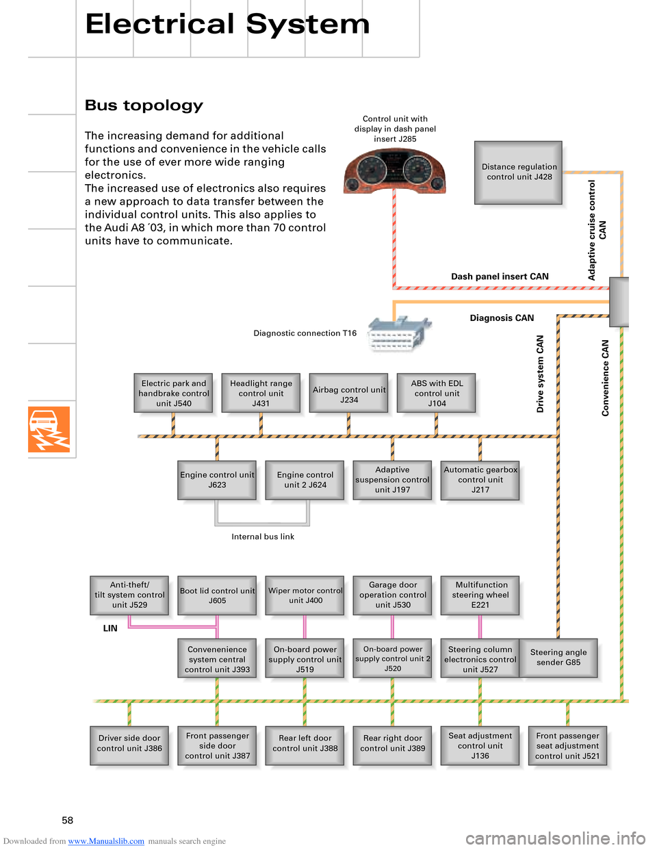
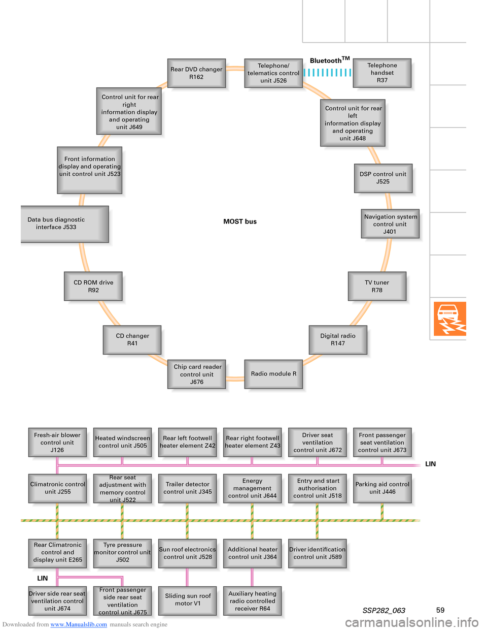
The increasing demand for additional
functions and convenience in the vehicle calls
for the use of ever more wide ranging
electronics.
The increased use of electronics also requires
a new approach to data transfer between the
individual control units. This also applies to
the Audi A8 ´03, in which more than 70 control
units have to communicate.
Distance regulation
control unit J428
Electric park and
handbrake control
unit J540Headlight range
control unit
J431Airbag control unit
J234ABS with EDL
control unit
J104
Engine control unit
J623Adaptive
suspension control
unit J197 Engine control
unit 2 J624Automatic gearbox
control unit
J217
Anti-theft/
tilt system control
unit J529
Boot lid control unit
J605Wiper motor control
unit J400Garage door
operation control
unit J530 Multifunction
steering wheel
E221
Convenenience
system central
control unit J393On-board power
supply control unit
J519
On-board power
supply control unit 2
J520Steering column
electronics control
unit J527Steering angle
sender G85
Driver side door
control unit J386Front passenger
side door
control unit J387Rear left door
control unit J388Rear right door
control unit J389Seat adjustment
control unit
J136Front passenger
seat adjustment
control unit J521 Control unit with
display in dash panel
insert J285
Diagnostic connection T16
Dash panel insert CAN
Drive system CAN
Diagnosis CAN
Convenience CAN
Internal bus link
LIN
Adaptive cruise control
CAN
Page 59 of 96
Downloaded from www.Manualslib.com manuals search engine 59SSP282_063
Telephone/
telematics control
unit J526
Front information
display and operating
unit control unit J523Rear DVD changer
R162Telephone
handset
R37
Control unit for rear
left
information display
and operating
unit J648
DSP control unit
J525
Navigation system
control unit
J401
TV tuner
R78
Digital radio
R147
Radio module R Chip card reader
control unit
J676 CD changer
R41 CD ROM drive
R92 Data bus diagnostic
interface J533
Fresh-air blower
control unit
J126Heated windscreen
control unit J505Rear left footwell
heater element Z42Rear right footwell
heater element Z43Driver seat
ventilation
control unit J672Front passenger
seat ventilation
control unit J673
Parking aid control
unit J446 Entry and start
authorisation
control unit J518 Energy
management
control unit J644 Rear seat
adjustment with
memory control
unit J522 Climatronic control
unit J255
Trailer detector
control unit J345
Rear Climatronic
control and
display unit E265Tyre pressure
monitor control unit
J502
Sun roof electronics
control unit J528
Additional heater
control unit J364Driver identification
control unit J589
Auxiliary heating
radio controlled
receiver R64 Sliding sun roof
motor V1 Front passenger
side rear seat
ventilation
control unit J675 Driver side rear seat
ventilation control
unit J674 Control unit for rear
right
information display
and operating
unit J649
MOST busBluetooth
TM
LIN
LIN
Page 64 of 96
Downloaded from www.Manualslib.com manuals search engine 64
Electrical System
Convenience and security
electronics
"Advanced Key" entry and start
authorisation system
"Advanced Key" can be taken to mean an
"advanced locking and security system".
It takes the form of a non-contacting key
recognition system. With the "Advanced Key"
package, the "Vehicle unlocking" and "Vehicle
locking" functions by way of a mechanical or
remote control key are supplemented by the non-
contacting functions "Vehicle unlocking" and
"Vehicle locking".
Functions
Advanced Key "unlocking"
The key owner enters the key detection zone next
to the vehicle (less than 1.5 m from door handle)
and reaches into the recessed handle moulding.
aerial.
The key responds by way of radio waves and the
vehicle is unlocked if authorised.
Advanced Key "starting"
The driver presses the start button, which again
initiates a key scan via the passenger-
compartment aerials near the selector lever, at the
rear centre vents and at the rear centre armrest.
The remote control key provides confirmation,
with the result that the ignition is switched on on
depressing the first stage of the start button and
the engine started on depressing the second
stage. The engine is switched off with the STOP
button.
Advanced Key "locking"
If the vehicle is to be locked from the outside, it is
sufficient to press the locking button in one of the
door handles. Actuation of the locking button
triggers a key scan via the door handle aerial and
the vehicle is locked on confirmation of the remote
control key.In addition, the driver can start the engine
with the START/STOP button (START/STOP
function) without inserting the ignition key
in the electronic ignition lock.
SSP282_093
SSP282_094
SSP282_095
Design and operation are described in
SSP 287 – Audi A8 ´03 Electrical
Components.
A proximity sensor starts a key scan by way of an