Page 82 of 114

PERIODIC MAINTENANCE AND MINOR REPAIR
6-33
6
EAU02939
Checking the front fork The condition and operation of the front
fork must be checked as follows at the
intervals specified in the periodic main-
tenance and lubrication chart.
To check the condition
EW000115
WARNING
_ Securely support the motorcycle so
that there is no danger of it falling
over. _Check the inner tubes for scratches,
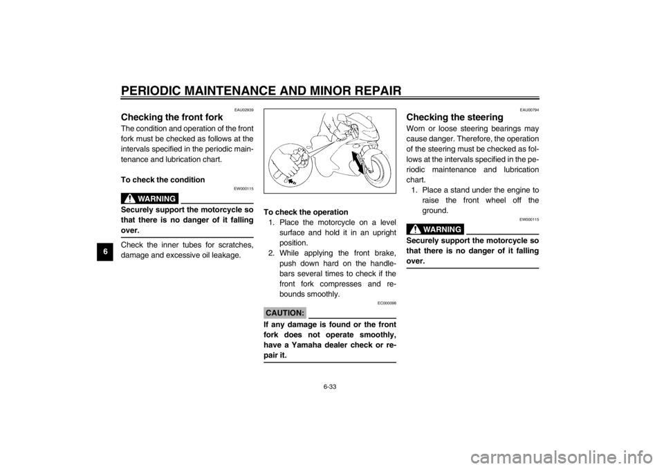
damage and excessive oil leakage.To check the operation
1. Place the motorcycle on a level
surface and hold it in an upright
position.
2. While applying the front brake,
push down hard on the handle-
bars several times to check if the
front fork compresses and re-
bounds smoothly.
EC000098
CAUTION:_ If any damage is found or the front
fork does not operate smoothly,
have a Yamaha dealer check or re-
pair it. _
EAU00794
Checking the steering Worn or loose steering bearings may
cause danger. Therefore, the operation
of the steering must be checked as fol-
lows at the intervals specified in the pe-
riodic maintenance and lubrication
chart.
1. Place a stand under the engine to
raise the front wheel off the
ground.
EW000115
WARNING
_ Securely support the motorcycle so
that there is no danger of it falling
over. _
U4TVE6.book Page 33 Saturday, August 4, 2001 12:14 PM
Page 83 of 114
PERIODIC MAINTENANCE AND MINOR REPAIR
6-34
6 2. Hold the lower ends of the front
fork legs and try to move them for-
ward and backward. If any free
play can be felt, have a Yamaha
dealer check or repair the steer-
ing.
EAU01144
Checking the wheel bearings The front and rear wheel bearings must
be checked at the intervals specified in
the periodic maintenance and lubrica-
tion chart. If there is play in the wheel
hub or if the wheel does not turn
smoothly, have a Yamaha dealer
check the wheel bearings.
U4TVE6.book Page 34 Saturday, August 4, 2001 12:14 PM
Page 88 of 114

PERIODIC MAINTENANCE AND MINOR REPAIR
6-39
6
EAU03497
Replacing a turn signal light
bulb 1. Remove the turn signal light lens
by removing the screw.
2. Remove the defective bulb by
pushing it in and turning it counter-
clockwise.
3. Insert a new bulb into the socket,
push it in, and then turn it clock-
wise until it stops.
4. Install the lens by installing the
screw.
ECA00065
CAUTION:_ Do not overtighten the screw, other-
wise the lens may break. _
EAU01579
Supporting the motorcycle Since this model is not equipped with a
centerstand, follow these precautions
when removing the front and rear
wheel or performing other mainte-
nance requiring the motorcycle to
stand upright. Check that the motor-
cycle is in a stable and level position
before starting any maintenance. A
strong wooden box can be placed un-
der the engine for added stability.
To service the front wheel
1. Stabilize the rear of the motorcycle
by using a motorcycle stand or, if
an additional motorcycle stand is
not available, by placing a jack un-
der the frame in front of the rear
wheel.
2. Raise the front wheel off the
ground by using a motorcycle
stand.To service the rear wheel
Raise the rear wheel off the ground by
using a motorcycle stand or, if a motor-
cycle stand is not available, by placing
a jack either under each side of the
frame in front of the rear wheel or under
each side of the swingarm.
1. ScrewU4TVE6.book Page 39 Saturday, August 4, 2001 12:14 PM
Page 89 of 114

PERIODIC MAINTENANCE AND MINOR REPAIR
6-40
6
EAU03582
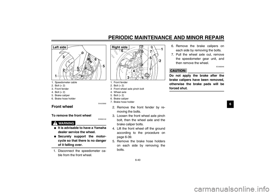
Front wheel To remove the front wheel
EW000122
WARNING
_ �
It is advisable to have a Yamaha
dealer service the wheel.
�
Securely support the motor-
cycle so that there is no danger
of it falling over.
_1. Disconnect the speedometer ca-
ble from the front wheel.2. Remove the front fender by re-
moving the bolts.
3. Loosen the front wheel axle pinch
bolt, then the wheel axle and the
brake caliper bolts.
4. Lift the front wheel off the ground
according to the procedure on
page 6-39.
5. Remove the brake hose holders
on each side by removing the
bolts.6. Remove the brake calipers on
each side by removing the bolts.
7. Pull the wheel axle out, remove
the speedometer gear unit, and
then remove the wheel.
ECA00046
CAUTION:_ Do not apply the brake after the
brake calipers have been removed,
otherwise the brake pads will be
forced shut. _
1. Speedometer cable
2. Bolt (× 2)
3. Front fender
4. Bolt (× 2)
5. Brake caliper
6. Brake hose holderLeft side
1. Front fender
2. Bolt (× 2)
3 Front wheel axle pinch bolt
4. Wheel axle
5. Bolt (× 2)
6. Brake caliper
7. Brake hose holderRight side
U4TVE6.book Page 40 Saturday, August 4, 2001 12:14 PM
Page 90 of 114

PERIODIC MAINTENANCE AND MINOR REPAIR
6-41
6
EAU04196
To install the front wheel
1. Install the speedometer gear unit
into the wheel hub so that the pro-
jections mesh with the slots.
2. Lift the wheel up between the fork
legs.NOTE:_ Make sure that the slot in the speedom-
eter gear unit fits over the retainer on
the fork leg. _3. Insert the wheel axle.
4. Lower the front wheel so that it is
on the ground.5. Install the brake calipers by install-
ing the bolts.
NOTE:_ Make sure that there is enough space
between the brake pads before install-
ing the brake calipers onto the brake
discs. _6. Tighten the wheel axle, then the
front wheel axle pinch bolt and the
brake caliper bolts to the specified
torques.
7. Install the brake hose holders by
installing the bolts.
8. Connect the speedometer cable.
9. Install the front fender by installing
the bolts.
10. Push down hard on the handlebar
several times to check for proper
fork operation.
EAU04197
Rear wheel To remove the rear wheel
EW000122
WARNING
_ �
It is advisable to have a Yamaha
dealer service the wheel.
�
Securely support the motor-
cycle so that there is no danger
of it falling over.
_
1. Speedometer gear unit
2. Slot
3. Speedometer gear unit retainer
Tightening torques:
Wheel axle:
65 Nm (6.5 m·kgf)
Front wheel axle pinch bolt:
20 Nm (2.0 m·kgf)
Brake caliper bolt:
40 Nm (4.0 m·kgf)
1. Axle nut
2. Left wheel axle guide
3. Locknut
4. Drive chain slack adjusting nut
5. Wheel axle
U4TVE6.book Page 41 Saturday, August 4, 2001 12:14 PM
Page 91 of 114

PERIODIC MAINTENANCE AND MINOR REPAIR
6-42
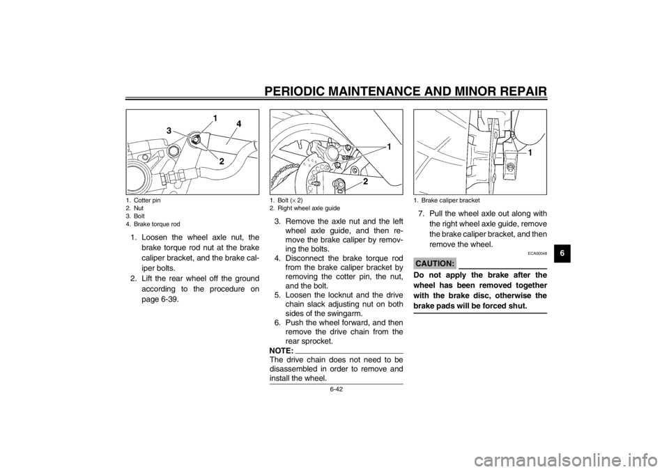
6 1. Loosen the wheel axle nut, the
brake torque rod nut at the brake
caliper bracket, and the brake cal-
iper bolts.
2. Lift the rear wheel off the ground
according to the procedure on
page 6-39.3. Remove the axle nut and the left
wheel axle guide, and then re-
move the brake caliper by remov-
ing the bolts.
4. Disconnect the brake torque rod
from the brake caliper bracket by
removing the cotter pin, the nut,
and the bolt.
5. Loosen the locknut and the drive
chain slack adjusting nut on both
sides of the swingarm.
6. Push the wheel forward, and then
remove the drive chain from the
rear sprocket.
NOTE:_ The drive chain does not need to be
disassembled in order to remove and
install the wheel. _
7. Pull the wheel axle out along with
the right wheel axle guide, remove
the brake caliper bracket, and then
remove the wheel.
ECA00048
CAUTION:_ Do not apply the brake after the
wheel has been removed together
with the brake disc, otherwise the
brake pads will be forced shut. _
1. Cotter pin
2. Nut
3. Bolt
4. Brake torque rod
1. Bolt (× 2)
2. Right wheel axle guide
1. Brake caliper bracket
U4TVE6.book Page 42 Saturday, August 4, 2001 12:14 PM
Page 92 of 114

PERIODIC MAINTENANCE AND MINOR REPAIR
6-43
6
EAU04283
To install the rear wheel
1. Install the wheel, right wheel axle
guide, and caliper bracket by in-
serting the wheel axle from the
right-hand side.
2. Install the drive chain onto the rear
sprocket, and then install the left
wheel axle guide and the axle nut.
3. Install the brake caliper by install-
ing the bolts, and then connect the
brake torque rod to the brake cali-
per bracket by installing the bolt
and nut.NOTE:_ Make sure that there is enough space
between the brake pads before installing
the brake caliper onto the brake disc. _
4. Adjust the drive chain slack. (See
page 6-29 for drive chain slack ad-
justment procedures.)
5. Lower the rear wheel so that it is
on the ground.
6. Tighten the axle nut, the brake cal-
iper bolts and the brake torque rod
nut to the specified torques.
7. Install a new cotter pin into the
brake torque rod bolt.
EWA00051
WARNING
_ Always use a new cotter pin for the
brake torque rod bolt. _
EAU03087
Troubleshooting Although Yamaha motorcycles receive
a thorough inspection before shipment
from the factory, trouble may occur dur-
ing operation. Any problem in the fuel,
compression, or ignition systems, for
example, can cause poor starting and
loss of power.
The following troubleshooting charts
represent quick and easy procedures
for checking these vital systems your-
self. However, should your motorcycle
require any repair, take it to a Yamaha
dealer, whose skilled technicians have
the necessary tools, experience, and
know-how to service the motorcycle
properly.
Use only genuine Yamaha replace-
ment parts. Imitation parts may look
like Yamaha parts, but they are often
inferior, have a shorter service life and
can lead to expensive repair bills.
Tightening torques:
Axle nut:
117 Nm (11.7 m·kgf)
Brake caliper bolt:
40 Nm (4.0 m·kgf)
Brake torque rod nut:
30 Nm (3.0 m·kgf)
U4TVE6.book Page 43 Saturday, August 4, 2001 12:14 PM
Page 96 of 114

7-1
7
EAU03426
7-MOTORCYCLE CARE AND STORAGECare While the open design of a motorcycle
reveals the attractiveness of the tech-
nology, it also makes it more vulnera-
ble. Rust and corrosion can develop
even if high-quality components are
used. A rusty exhaust pipe may go un-
noticed on a car, however, it detracts
from the overall appearance of a
motorcycle. Frequent and proper care
does not only comply with the terms of
the warranty, but it will also keep your
motorcycle looking good, extend its life
and optimize its performance.Before cleaning
1. Cover the muffler outlet with a
plastic bag after the engine has
cooled down.
2. Make sure that all caps and covers
as well as all electrical couplers
and connectors, including the
spark plug caps, are tightly in-
stalled.
3. Remove extremely stubborn dirt,
like oil burnt onto the crankcase,
with a degreasing agent and a
brush, but never apply such prod-
ucts onto seals, gaskets, sprock-
ets, the drive chain and wheel
axles. Always rinse the dirt and
degreaser off with water.Cleaning
ECA00010
CAUTION:_ �
Avoid using strong acidic wheel
cleaners, especially on spoked
wheels. If such products are
used on hard-to-remove dirt, do
not leave the cleaner on the af-
fected area any longer than in-
structed. Also, thoroughly rinse
the area off with water, immedi-
ately dry it, and then apply a
corrosion protection spray.
�
Improper cleaning can damage
windshields, cowlings, panels
and other plastic parts. Use
only a soft, clean cloth or
sponge with mild detergent and
water to clean plastic.
U4TVE6.book Page 1 Saturday, August 4, 2001 12:14 PM