Page 12 of 104
2-1
2
EAU00026
2-DESCRIPTION Left view1. Engine oil drain bolt (crankcase) (page 6-10)
2. Shift pedal (page 3-7)
3. Starter (choke) knob (page 3-12)
4. Fuel cock (page 3-11)
5. Rider seat (page 3-12)
6. Owner’s tool kit (page 6-1)7. Helmet holder (page 3-13)
8. Rear turn signal lights (page 6-38)
9. Tail/brake light (page 6-38)
10. Fuses (page 6-35)
E_5JA.book Page 1 Saturday, August 18, 2001 3:52 PM
Page 13 of 104
DESCRIPTION
2-2
2
Right view11. Passenger footrest
12. Passenger seat
13. Engine oil filler cap (page 6-8)
14. Fuel tank (page 3-9)
15. Fuel tank cap (page 3-9)
16. Headlight (page 6-36)
17. Front turn signal lights (page 6-38)
18. Throttle stop screw (page 6-16)19. Brake pedal (page 3-8)
20. Engine oil filter cartridge (page 6-10)
21. Rider footrest
22. Engine oil drain bolt (oil tank) (page 6-9)
23. Transfer case oil drain bolt (page 6-12)
24. Shock absorber assembly spring
preload adjusting nut (page 3-14)
25. Muffler
E_5JA.book Page 2 Saturday, August 18, 2001 3:52 PM
Page 15 of 104

3
INSTRUMENT AND CONTROL FUNCTIONS
Main switch/steering lock ..................................... 3-1
Indicator and warning lights ................................ 3-2
Speedometer unit ................................................ 3-3
Self-diagnosis device ........................................... 3-4
Fuel gauge ........................................................... 3-4
Anti-theft alarm (optional) .................................... 3-4
Clock .................................................................... 3-5
Handlebar switches ............................................. 3-6
Clutch lever .......................................................... 3-7
Shift pedal ............................................................ 3-7
Brake lever ........................................................... 3-8
Brake pedal .......................................................... 3-8Fuel tank cap ...................................................... 3-9
Fuel ..................................................................... 3-9
Fuel tank breather hose .................................... 3-10
Fuel cock ........................................................... 3-11
Starter (choke) knob ......................................... 3-12
Locking the steering with a padlock .................. 3-12
Rider seat .......................................................... 3-12
Helmet holder .................................................... 3-13
Adjusting the shock absorber assembly ............ 3-14
Sidestand .......................................................... 3-15
Ignition circuit cut-off system ............................. 3-16
E_5JA.book Page 1 Saturday, August 18, 2001 3:52 PM
Page 17 of 104

The steering is locked, and the taillight
and auxiliary light are on, but all other
electrical systems are off. The key can
be removed.
The s")
INSTRUMENT AND CONTROL FUNCTIONS
3-2
3
EAU01590
(Parking)
The steering is locked, and the taillight
and auxiliary light are on, but all other
electrical systems are off. The key can
be removed.
The steering must be locked before the
key can be turned to “”.
ECA00043
CAUTION:@ Do not use the parking position for
an extended length of time, other-
wise the battery may discharge. @
EAU03034
Indicator and warning lights
EAU00079
Fuel level warning light “”
This warning light comes on when the
fuel level drops below approximately
3.5 L. When this occurs, turn the fuel
cock lever to the “RES” position and re-
fuel as soon as possible.
EAU00063
High beam indicator light “”
This indicator light comes on when the
high beam of the headlight is switched
on.
EAU00057
Turn signal indicator light “”
This indicator light flashes when the
turn signal switch is pushed to the left
or right.
EAU00061
Neutral indicator light “”
This indicator light comes on when the
transmission is in the neutral position.
EAU00091
Engine trouble warning light “”
This warning light comes on or flashes
when an electrical circuit monitoring
the engine is defective. When this oc-
curs, have the Yamaha dealer check
the self-diagnosis system.
1. Fuel level warning light “”
2. High beam indicator light “”
3. Turn signal indicator light “”
4. Neutral indicator light “”
5. Engine trouble warning light “”
E_5JA.book Page 2 Saturday, August 18, 2001 3:52 PM
Page 21 of 104

INSTRUMENT AND CONTROL FUNCTIONS
3-6
3
EAU00118
Handlebar switches
EAU00119
Pass switch “”
Press this switch to flash the headlight.
EAU03888
Dimmer switch “/”
Set this switch to “” for the high
beam and to “” for the low beam.
EAU03889
Turn signal switch “/”
To signal a right-hand turn, push this
switch to “”. To signal a left-hand
turn, push this switch to “”. When
released, the switch returns to the cen-
ter position. To cancel the turn signal
lights, push the switch in after it has re-
turned to the center position.
EAU00129
Horn switch “”
Press this switch to sound the horn.
EAU03890
Engine stop switch “/”
Set this switch to “” before starting
the engine. Set this switch to “” to
stop the engine in case of an emergen-
cy, such as when the motorcycle over-
turns or when the throttle cable is
stuck.
EAU03898
Light switch “//”
Set this switch to “” to turn on the
auxiliary light, meter lighting and tail-
light. Set the switch to “” to turn on
the headlight also. Set the switch to
“” to turn off all the lights.
1. Pass switch “”
2. Dimmer switch “/”
3. Turn signal switch “/”
4. Horn switch “”
1. Engine stop switch “/”
2. Light switch “//”
3. Start switch “”
E_5JA.book Page 6 Saturday, August 18, 2001 3:52 PM
Page 35 of 104

PRE-OPERATION CHECKS
4-2
4
NOTE:@ Pre-operation checks should be made each time the motorcycle is used. Such an inspection can be accomplished in a very
short time; and the added safety it assures is more than worth the time involved. @
EWA00033
WARNING
@ If any item in the Pre-operation check list is not working properly, have it inspected and repaired before operating
the motorcycle. @Control cablesMake sure that operation is smooth.
Lubricate if necessary.—
Wheels and tiresCheck for damage.
Check tire condition and tread depth.
Check air pressure.
Correct if necessary.6-17–6-20
Brake and shift pedalsMake sure that operation is smooth.
Lubricate pedal pivoting points if necessary.6-29
Brake and clutch leversMake sure that operation is smooth.
Lubricate lever pivoting points if necessary.6-30
SidestandMake sure that operation is smooth.
Lubricate pivot if necessary.6-30
Chassis fastenersMake sure that all nuts, bolts and screws are properly tightened.
Tighten if necessary.—
Instruments, lights, signals
and switchesCheck operation.
Correct if necessary.—
Sidestand switchCheck operation of ignition circuit cut-off system.
If system is defective, have Yamaha dealer check vehicle.3-16 ITEM CHECKS PAGE
E_5JA.book Page 2 Saturday, August 18, 2001 3:52 PM
Page 41 of 104
 The recommended shift points during
acceleration are shown in the table be-
low.CF-01ENOTE:@ When")
OPERATION AND IMPORTANT RIDING POINTS
5-4
5
EAU02941
Recommended shift points
(for Switzerland only) The recommended shift points during
acceleration are shown in the table be-
low.CF-01ENOTE:@ When shifting down two gears at a
time, reduce the speed accordingly
(e.g., down to 35 km/h when shifting
from 4th to 2nd gear). @
EAU00424
Tips for reducing fuel
consumption Fuel consumption depends largely on
your riding style. Consider the following
tips to reduce fuel consumption:�
Thoroughly warm up the engine.
�
Turn the starter (choke) off as
soon as possible.
�
Shift up swiftly, and avoid high en-
gine speeds during acceleration.
�
Do not rev the engine while shift-
ing down, and avoid high engine
speeds with no load on the engine.
�
Turn the engine off instead of let-
ting it idle for an extended length
of time (e.g., in traffic jams, at traf-
fic lights or at railroad crossings).
Shift point
(km/h)
1st→2nd
2nd→3rd
3rd→4th
4th→5th23
36
50
60
E_5JA.book Page 4 Saturday, August 18, 2001 3:52 PM
Page 50 of 104
PERIODIC MAINTENANCE AND MINOR REPAIR
6-5
6
EAU03884
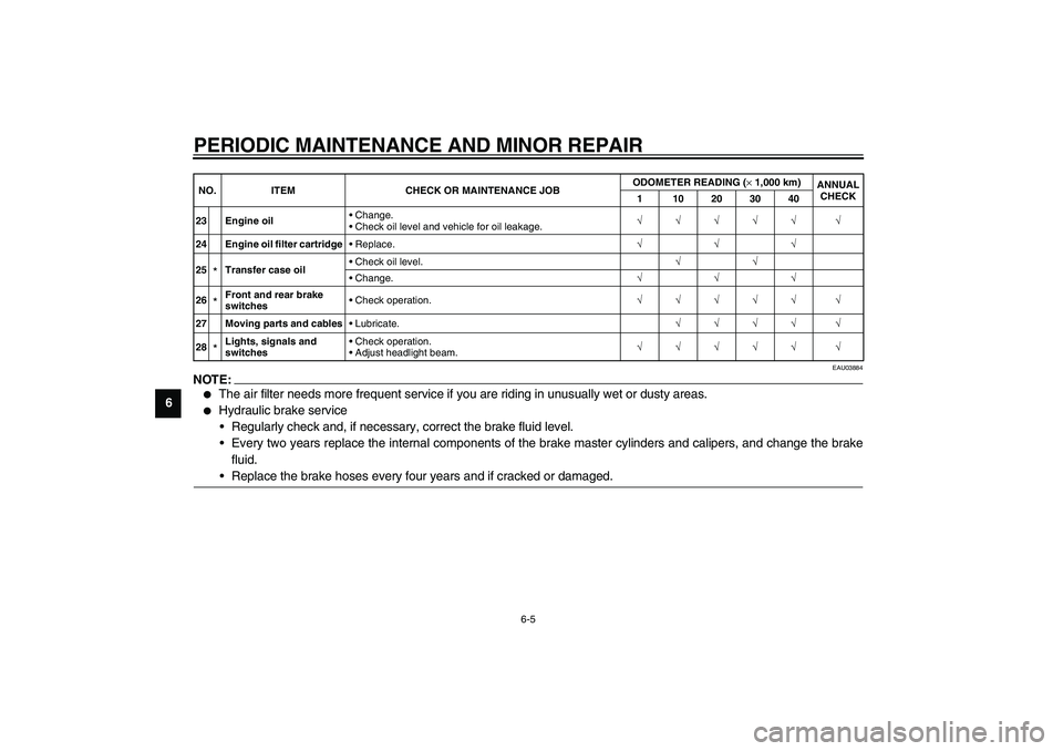
NOTE:_ �
The air filter needs more frequent service if you are riding in unusually wet or dusty areas.
�
Hydraulic brake service
Regularly check and, if necessary, correct the brake fluid level.
Every two years replace the internal components of the brake master cylinders and calipers, and change the brake
fluid.
Replace the brake hoses every four years and if cracked or damaged.
_23 Engine oilChange.
Check oil level and vehicle for oil leakage.√√√√√ √
24 Engine oil filter cartridgeReplace.√√√
25
*Transfer case oilCheck oil level.√√
Change.√√√
26*Front and rear brake
switchesCheck operation.√√√√√ √
27 Moving parts and cablesLubricate.√√√√ √
28*Lights, signals and
switchesCheck operation.
Adjust headlight beam.√√√√√ √ NO. ITEM CHECK OR MAINTENANCE JOBODOMETER READING (×1,000 km)
ANNUAL
CHECK
1 10203040
E_5JA_Periodic.fm Page 5 Saturday, August 18, 2001 5:37 PM
 (page 6-10)
2. Shift pedal (page 3-7)
3. Starter (choke) knob (page 3-12)
4. Fuel cock (page 3-11)
5. Rider seat (page 3-12)")

14. Fuel tank (page 3-9)
15. Fuel tank cap (page 3-9)
16. Headlight (page 6-36)
17. Front tur")