2002 YAMAHA XJ900S warning lights
[x] Cancel search: warning lightsPage 15 of 102

3
INSTRUMENT AND CONTROL FUNCTIONS
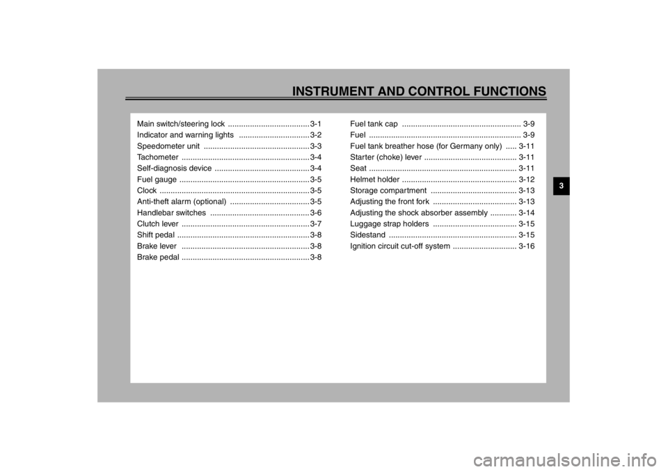
Main switch/steering lock ..................................... 3-1
Indicator and warning lights ................................ 3-2
Speedometer unit ................................................ 3-3
Tachometer .......................................................... 3-4
Self-diagnosis device ........................................... 3-4
Fuel gauge ........................................................... 3-5
Clock .................................................................... 3-5
Anti-theft alarm (optional) .................................... 3-5
Handlebar switches ............................................. 3-6
Clutch lever .......................................................... 3-7
Shift pedal ............................................................ 3-8
Brake lever .......................................................... 3-8
Brake pedal .......................................................... 3-8Fuel tank cap ...................................................... 3-9
Fuel ..................................................................... 3-9
Fuel tank breather hose (for Germany only) ..... 3-11
Starter (choke) lever .......................................... 3-11
Seat ................................................................... 3-11
Helmet holder .................................................... 3-12
Storage compartment ....................................... 3-13
Adjusting the front fork ...................................... 3-13
Adjusting the shock absorber assembly ............ 3-14
Luggage strap holders ...................................... 3-15
Sidestand .......................................................... 3-15
Ignition circuit cut-off system ............................. 3-16
E_4km.book Page 1 Tuesday, August 28, 2001 9:51 AM
Page 17 of 102

INSTRUMENT AND CONTROL FUNCTIONS
3-2
3
EAU04356
(Parking)
The steering is locked, the taillight and
auxiliary light are on, and the hazard
light can be turned on, but all other
electrical systems are off. The key can
be removed.
The steering must be locked before the
key can be turned to “”.
ECA00043
CAUTION:_ Do not use the parking position for
an extended length of time, other-
wise the battery may discharge. _
EAU03034
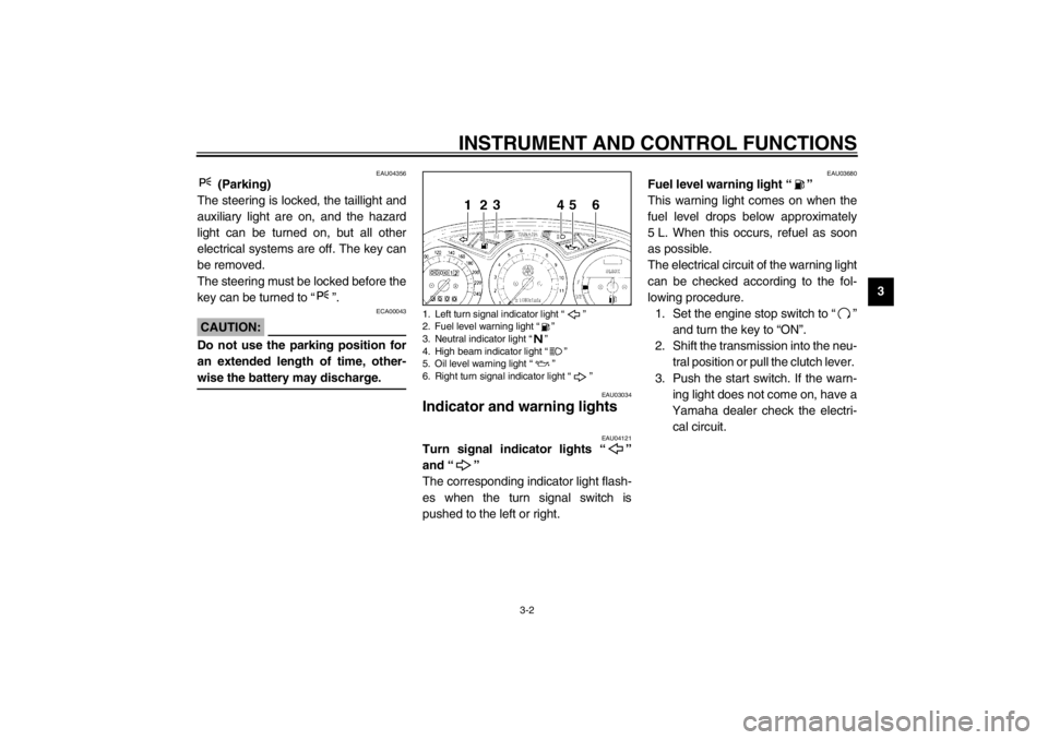
Indicator and warning lights
EAU04121
Turn signal indicator lights “”
and “”
The corresponding indicator light flash-
es when the turn signal switch is
pushed to the left or right.
EAU03680
Fuel level warning light “”
This warning light comes on when the
fuel level drops below approximately
5 L. When this occurs, refuel as soon
as possible.
The electrical circuit of the warning light
can be checked according to the fol-
lowing procedure.
1. Set the engine stop switch to “”
and turn the key to “ON”.
2. Shift the transmission into the neu-
tral position or pull the clutch lever.
3. Push the start switch. If the warn-
ing light does not come on, have a
Yamaha dealer check the electri-
cal circuit.
1. Left turn signal indicator light “”
2. Fuel level warning light “”
3. Neutral indicator light “”
4. High beam indicator light “”
5. Oil level warning light “”
6. Right turn signal indicator light “”
E_4km.book Page 2 Tuesday, August 28, 2001 9:51 AM
Page 35 of 102

PRE-OPERATION CHECKS
4-2
4
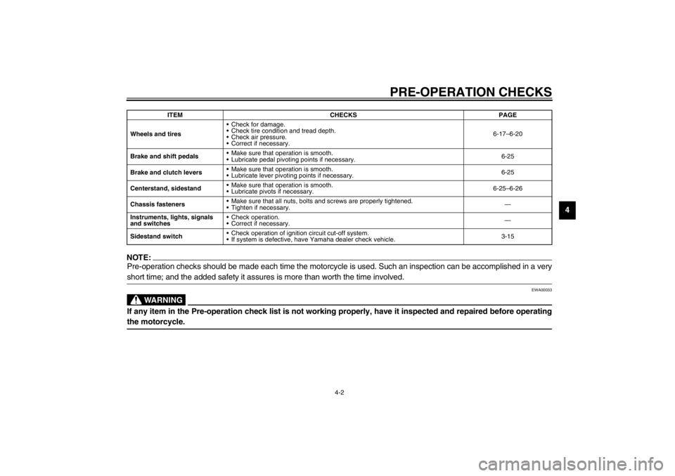
NOTE:@ Pre-operation checks should be made each time the motorcycle is used. Such an inspection can be accomplished in a very
short time; and the added safety it assures is more than worth the time involved. @
EWA00033
WARNING
@ If any item in the Pre-operation check list is not working properly, have it inspected and repaired before operating
the motorcycle. @Wheels and tiresCheck for damage.
Check tire condition and tread depth.
Check air pressure.
Correct if necessary.6-17–6-20
Brake and shift pedalsMake sure that operation is smooth.
Lubricate pedal pivoting points if necessary.6-25
Brake and clutch leversMake sure that operation is smooth.
Lubricate lever pivoting points if necessary.6-25
Centerstand, sidestandMake sure that operation is smooth.
Lubricate pivots if necessary.6-25–6-26
Chassis fastenersMake sure that all nuts, bolts and screws are properly tightened.
Tighten if necessary.—
Instruments, lights, signals
and switchesCheck operation.
Correct if necessary.—
Sidestand switchCheck operation of ignition circuit cut-off system.
If system is defective, have Yamaha dealer check vehicle.3-15 ITEM CHECKS PAGE
E_4km.book Page 2 Tuesday, August 28, 2001 9:51 AM
Page 98 of 102

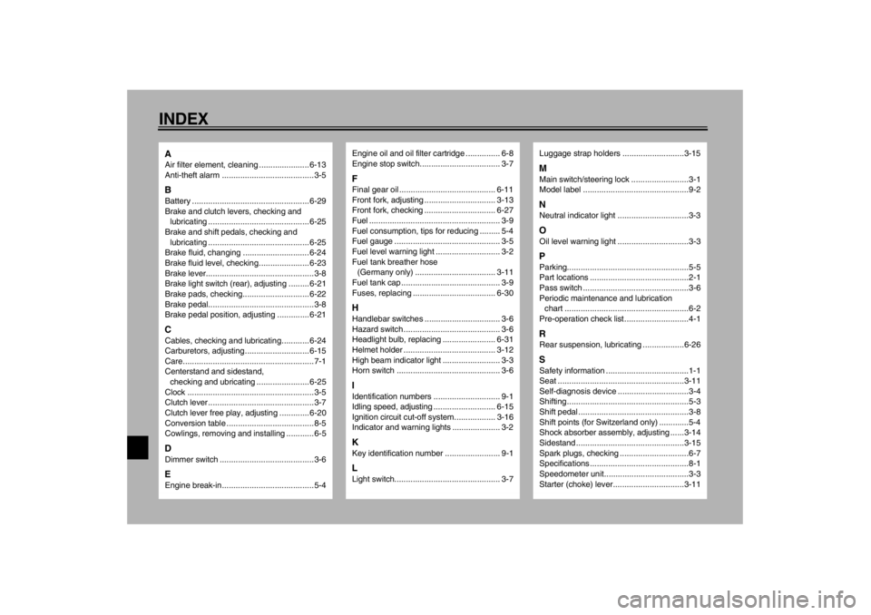
10-INDEXAAir filter element, cleaning ...................... 6-13
Anti-theft alarm ........................................3-5BBattery ................................................... 6-29
Brake and clutch levers, checking and
lubricating ............................................ 6-25
Brake and shift pedals, checking and
lubricating ............................................ 6-25
Brake fluid, changing ............................. 6-24
Brake fluid level, checking...................... 6-23
Brake lever...............................................3-8
Brake light switch (rear), adjusting ......... 6-21
Brake pads, checking............................. 6-22
Brake pedal..............................................3-8
Brake pedal position, adjusting .............. 6-21CCables, checking and lubricating............ 6-24
Carburetors, adjusting............................ 6-15
Care.........................................................7-1
Centerstand and sidestand,
checking and ubricating ....................... 6-25
Clock .......................................................3-5
Clutch lever ..............................................3-7
Clutch lever free play, adjusting ............. 6-20
Conversion table ......................................8-5
Cowlings, removing and installing ............6-5DDimmer switch .........................................3-6EEngine break-in........................................5-4
Engine oil and oil filter cartridge ............... 6-8
Engine stop switch................................... 3-7FFinal gear oil .......................................... 6-11
Front fork, adjusting ............................... 3-13
Front fork, checking ............................... 6-27
Fuel ......................................................... 3-9
Fuel consumption, tips for reducing ......... 5-4
Fuel gauge .............................................. 3-5
Fuel level warning light ............................ 3-2
Fuel tank breather hose
(Germany only) ................................... 3-11
Fuel tank cap ........................................... 3-9
Fuses, replacing .................................... 6-30HHandlebar switches ................................. 3-6
Hazard switch .......................................... 3-6
Headlight bulb, replacing ....................... 6-31
Helmet holder ........................................ 3-12
High beam indicator light ......................... 3-3
Horn switch ............................................. 3-6IIdentification numbers ............................. 9-1
Idling speed, adjusting ........................... 6-15
Ignition circuit cut-off system.................. 3-16
Indicator and warning lights ..................... 3-2KKey identification number ........................ 9-1LLight switch.............................................. 3-7
Luggage strap holders ...........................3-15MMain switch/steering lock .........................3-1
Model label ..............................................9-2NNeutral indicator light ...............................3-3OOil level warning light ...............................3-3PParking.....................................................5-5
Part locations ...........................................2-1
Pass switch ..............................................3-6
Periodic maintenance and lubrication
chart ......................................................6-2
Pre-operation check list ............................4-1RRear suspension, lubricating ..................6-26SSafety information ....................................1-1
Seat .......................................................3-11
Self-diagnosis device ...............................3-4
Shifting .....................................................5-3
Shift pedal ................................................3-8
Shift points (for Switzerland only) .............5-4
Shock absorber assembly, adjusting ......3-14
Sidestand ...............................................3-15
Spark plugs, checking ..............................6-7
Specifications ...........................................8-1
Speedometer unit.....................................3-3
Starter (choke) lever...............................3-11
E_4km.book Page 1 Tuesday, August 28, 2001 9:51 AM