Page 14 of 102
DESCRIPTION
2-3
2
Controls and instruments1. Clutch lever (page 3-7)
2. Left handlebar switches (page 3-6)
3. Starter (choke) lever (page 3-11)
4. Speedometer unit (page 3-3)
5. Tachometer (page 3-4)
6. Fuel gauge (page 3-5)7. Clock (page 3-5)
8. Right handlebar switches (page 3-7)
9. Brake lever (page 3-8)
10. Throttle grip (page 6-16)
11. Main switch/steering lock (page 3-1)
E_4km.book Page 3 Tuesday, August 28, 2001 9:51 AM
Page 15 of 102

3
INSTRUMENT AND CONTROL FUNCTIONS
Main switch/steering lock ..................................... 3-1
Indicator and warning lights ................................ 3-2
Speedometer unit ................................................ 3-3
Tachometer .......................................................... 3-4
Self-diagnosis device ........................................... 3-4
Fuel gauge ........................................................... 3-5
Clock .................................................................... 3-5
Anti-theft alarm (optional) .................................... 3-5
Handlebar switches ............................................. 3-6
Clutch lever .......................................................... 3-7
Shift pedal ............................................................ 3-8
Brake lever .......................................................... 3-8
Brake pedal .......................................................... 3-8Fuel tank cap ...................................................... 3-9
Fuel ..................................................................... 3-9
Fuel tank breather hose (for Germany only) ..... 3-11
Starter (choke) lever .......................................... 3-11
Seat ................................................................... 3-11
Helmet holder .................................................... 3-12
Storage compartment ....................................... 3-13
Adjusting the front fork ...................................... 3-13
Adjusting the shock absorber assembly ............ 3-14
Luggage strap holders ...................................... 3-15
Sidestand .......................................................... 3-15
Ignition circuit cut-off system ............................. 3-16
E_4km.book Page 1 Tuesday, August 28, 2001 9:51 AM
Page 17 of 102

The steering is locked, the taillight and
auxiliary light are on, and the hazard
light can be turned on, but all other
electrical systems are")
INSTRUMENT AND CONTROL FUNCTIONS
3-2
3
EAU04356
(Parking)
The steering is locked, the taillight and
auxiliary light are on, and the hazard
light can be turned on, but all other
electrical systems are off. The key can
be removed.
The steering must be locked before the
key can be turned to “”.
ECA00043
CAUTION:_ Do not use the parking position for
an extended length of time, other-
wise the battery may discharge. _
EAU03034
Indicator and warning lights
EAU04121
Turn signal indicator lights “”
and “”
The corresponding indicator light flash-
es when the turn signal switch is
pushed to the left or right.
EAU03680
Fuel level warning light “”
This warning light comes on when the
fuel level drops below approximately
5 L. When this occurs, refuel as soon
as possible.
The electrical circuit of the warning light
can be checked according to the fol-
lowing procedure.
1. Set the engine stop switch to “”
and turn the key to “ON”.
2. Shift the transmission into the neu-
tral position or pull the clutch lever.
3. Push the start switch. If the warn-
ing light does not come on, have a
Yamaha dealer check the electri-
cal circuit.
1. Left turn signal indicator light “”
2. Fuel level warning light “”
3. Neutral indicator light “”
4. High beam indicator light “”
5. Oil level warning light “”
6. Right turn signal indicator light “”
E_4km.book Page 2 Tuesday, August 28, 2001 9:51 AM
Page 18 of 102

INSTRUMENT AND CONTROL FUNCTIONS
3-3
3
EAU00061
Neutral indicator light “”
This indicator light comes on when the
transmission is in the neutral position.
EAU00063
High beam indicator light “”
This indicator light comes on when the
high beam of the headlight is switched
on.
EAU03201
Oil level warning light “”
This warning light comes on when the
engine oil level is low.
The electrical circuit of the warning light
can be checked according to the fol-
lowing procedure.
1. Set the engine stop switch to “”
and turn the key to “ON”.
2. Shift the transmission into the neu-
tral position or pull the clutch lever.
3. Push the start switch. If the warn-
ing light does not come on while
pushing the start switch, have a
Yamaha dealer check the electri-
cal circuit.NOTE:@ Even if the oil level is sufficient, the
warning light may flicker when riding on
a slope or during sudden acceleration
or deceleration, but this is not a mal-
function. @
EAU00096
Speedometer unit The speedometer unit is equipped with
a speedometer, an odometer and a
tripmeter. The speedometer shows
riding speed. The odometer shows the
total distance traveled. The tripmeter
shows the distance traveled since it
was last set to zero with the reset but-
ton. The tripmeter can be used togeth-
er with the fuel gauge to estimate the
distance that can be traveled with a full
tank of fuel. This information will enable
you to plan future fuel stops.
1. Left turn signal indicator light “”
2. Fuel level warning light “”
3. Neutral indicator light “”
4. High beam indicator light “”
5. Oil level warning light “”
6. Right turn signal indicator light “”
1. Tripmeter
2. Odometer
3. Tripmeter reset button
E_4km.book Page 3 Tuesday, August 28, 2001 9:51 AM
Page 20 of 102
 as the fuel level
decreases. When the")
INSTRUMENT AND CONTROL FUNCTIONS
3-5
3
EAU00110
Fuel gauge The fuel gauge indicates the amount of
fuel in the fuel tank. The needle moves
towards “E” (Empty) as the fuel level
decreases. When the needle reaches
“E”, approximately 5 L of fuel remain in
the fuel tank. If this occurs, refuel as
soon as possible.NOTE:@ Do not allow the fuel tank to empty it-
self completely. @
EAU04357
Clock The digital clock shows the time re-
gardless of the main switch position.
To set the clock:
1. Push or hold the hour setting but-
ton “H” to change the hours.
2. Push or hold the minute setting
button “M” to change the minutes.NOTE:_ To set the clock after the power source
has been cut, first set the time to
1:00 AM, and then set the clock to the
correct time. _
EAU00109
Anti-theft alarm (optional) This motorcycle can be equipped with
an optional anti-theft alarm by a
Yamaha dealer. Contact a Yamaha
dealer for more information.
1. Fuel gauge
1. Digital clock
2. Minute setting button “M”
3. Hour setting button “H”
E_4km.book Page 5 Tuesday, August 28, 2001 9:51 AM
Page 24 of 102

INSTRUMENT AND CONTROL FUNCTIONS
3-9
3
EAU02935
Fuel tank cap To open the fuel tank cap
Open the fuel tank cap lock cover, in-
sert the key into the lock, and then turn
it 1/4 turn clockwise. The lock will be re-
leased and the fuel tank cap can be
opened.
To close the fuel tank cap
1. Push the fuel tank cap into posi-
tion with the key inserted in the
lock. 2. Turn the key counterclockwise to
the original position, remove it,
and then close the lock cover.
NOTE:@ The fuel tank cap cannot be closed un-
less the key is in the lock. In addition,
the key cannot be removed if the cap is
not properly closed and locked. @
EWA00025
WARNING
@ Make sure that the fuel tank cap is
properly closed before riding. @
EAU03753
Fuel Make sure that there is sufficient fuel in
the tank. Fill the fuel tank to the bottom
of the filler tube as shown.
EW000130
WARNING
_ �
Do not overfill the fuel tank, oth-
erwise it may overflow when the
fuel warms up and expands.
�
Avoid spilling fuel on the hot
engine.
_
1. Fuel tank cap lock cover
2. Unlock.
1. Fuel tank filler tube
2. Fuel level
E_4km.book Page 9 Tuesday, August 28, 2001 9:51 AM
Page 25 of 102
INSTRUMENT AND CONTROL FUNCTIONS
3-10
3
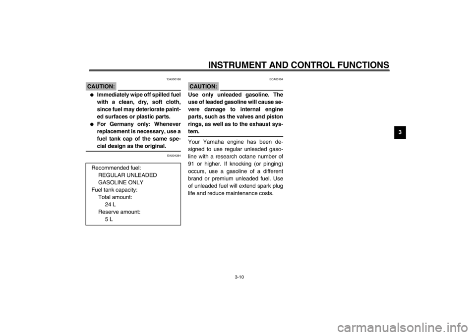
‘EAU00186
CAUTION:@ �
Immediately wipe off spilled fuel
with a clean, dry, soft cloth,
since fuel may deteriorate paint-
ed surfaces or plastic parts.
�
For Germany only: Whenever
replacement is necessary, use a
fuel tank cap of the same spe-
cial design as the original.
@
EAU04284ECA00104
CAUTION:_ Use only unleaded gasoline. The
use of leaded gasoline will cause se-
vere damage to internal engine
parts, such as the valves and piston
rings, as well as to the exhaust sys-
tem. _Your Yamaha engine has been de-
signed to use regular unleaded gaso-
line with a research octane number of
91 or higher. If knocking (or pinging)
occurs, use a gasoline of a different
brand or premium unleaded fuel. Use
of unleaded fuel will extend spark plug
life and reduce maintenance costs. Recommended fuel:
REGULAR UNLEADED
GASOLINE ONLY
Fuel tank capacity:
Total amount:
24 L
Reserve amount:
5 L
E_4km.book Page 10 Tuesday, August 28, 2001 9:51 AM
Page 26 of 102
INSTRUMENT AND CONTROL FUNCTIONS
3-11
3
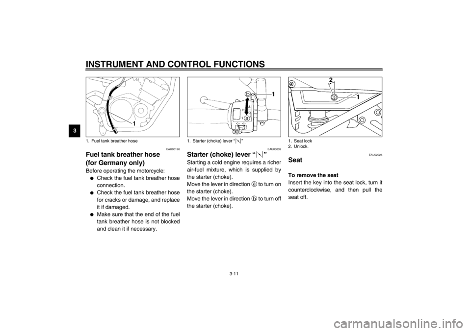
EAU00196
Fuel tank breather hose
(for Germany only) Before operating the motorcycle:�
Check the fuel tank breather hose
connection.
�
Check the fuel tank breather hose
for cracks or damage, and replace
it if damaged.
�
Make sure that the end of the fuel
tank breather hose is not blocked
and clean it if necessary.
EAU03839
Starter (choke) lever “” Starting a cold engine requires a richer
air-fuel mixture, which is supplied by
the starter (choke).
Move the lever in direction
a to turn on
the starter (choke).
Move the lever in direction
b to turn off
the starter (choke).
EAU02925
Seat To remove the seat
Insert the key into the seat lock, turn it
counterclockwise, and then pull the
seat off.
1. Fuel tank breather hose
1. Starter (choke) lever “”
1. Seat lock
2. Unlock.
E_4km.book Page 11 Tuesday, August 28, 2001 9:51 AM

2. Left handlebar switches (page 3-6)
3. Starter (choke) lever (page 3-11)
4. Speedometer unit (page 3-3)
5. Tachometer (page 3-4)")