Page 14 of 102
DESCRIPTION
2-3
2
Controls and instruments1. Clutch lever (page 3-7)
2. Left handlebar switches (page 3-6)
3. Starter (choke) lever (page 3-11)
4. Speedometer unit (page 3-3)
5. Tachometer (page 3-4)
6. Fuel gauge (page 3-5)7. Clock (page 3-5)
8. Right handlebar switches (page 3-7)
9. Brake lever (page 3-8)
10. Throttle grip (page 6-16)
11. Main switch/steering lock (page 3-1)
E_4km.book Page 3 Tuesday, August 28, 2001 9:51 AM
Page 15 of 102

3
INSTRUMENT AND CONTROL FUNCTIONS
Main switch/steering lock ..................................... 3-1
Indicator and warning lights ................................ 3-2
Speedometer unit ................................................ 3-3
Tachometer .......................................................... 3-4
Self-diagnosis device ........................................... 3-4
Fuel gauge ........................................................... 3-5
Clock .................................................................... 3-5
Anti-theft alarm (optional) .................................... 3-5
Handlebar switches ............................................. 3-6
Clutch lever .......................................................... 3-7
Shift pedal ............................................................ 3-8
Brake lever .......................................................... 3-8
Brake pedal .......................................................... 3-8Fuel tank cap ...................................................... 3-9
Fuel ..................................................................... 3-9
Fuel tank breather hose (for Germany only) ..... 3-11
Starter (choke) lever .......................................... 3-11
Seat ................................................................... 3-11
Helmet holder .................................................... 3-12
Storage compartment ....................................... 3-13
Adjusting the front fork ...................................... 3-13
Adjusting the shock absorber assembly ............ 3-14
Luggage strap holders ...................................... 3-15
Sidestand .......................................................... 3-15
Ignition circuit cut-off system ............................. 3-16
E_4km.book Page 1 Tuesday, August 28, 2001 9:51 AM
Page 20 of 102
 as the fuel level
decreases. When the")
INSTRUMENT AND CONTROL FUNCTIONS
3-5
3
EAU00110
Fuel gauge The fuel gauge indicates the amount of
fuel in the fuel tank. The needle moves
towards “E” (Empty) as the fuel level
decreases. When the needle reaches
“E”, approximately 5 L of fuel remain in
the fuel tank. If this occurs, refuel as
soon as possible.NOTE:@ Do not allow the fuel tank to empty it-
self completely. @
EAU04357
Clock The digital clock shows the time re-
gardless of the main switch position.
To set the clock:
1. Push or hold the hour setting but-
ton “H” to change the hours.
2. Push or hold the minute setting
button “M” to change the minutes.NOTE:_ To set the clock after the power source
has been cut, first set the time to
1:00 AM, and then set the clock to the
correct time. _
EAU00109
Anti-theft alarm (optional) This motorcycle can be equipped with
an optional anti-theft alarm by a
Yamaha dealer. Contact a Yamaha
dealer for more information.
1. Fuel gauge
1. Digital clock
2. Minute setting button “M”
3. Hour setting button “H”
E_4km.book Page 5 Tuesday, August 28, 2001 9:51 AM
Page 24 of 102

INSTRUMENT AND CONTROL FUNCTIONS
3-9
3
EAU02935
Fuel tank cap To open the fuel tank cap
Open the fuel tank cap lock cover, in-
sert the key into the lock, and then turn
it 1/4 turn clockwise. The lock will be re-
leased and the fuel tank cap can be
opened.
To close the fuel tank cap
1. Push the fuel tank cap into posi-
tion with the key inserted in the
lock. 2. Turn the key counterclockwise to
the original position, remove it,
and then close the lock cover.
NOTE:@ The fuel tank cap cannot be closed un-
less the key is in the lock. In addition,
the key cannot be removed if the cap is
not properly closed and locked. @
EWA00025
WARNING
@ Make sure that the fuel tank cap is
properly closed before riding. @
EAU03753
Fuel Make sure that there is sufficient fuel in
the tank. Fill the fuel tank to the bottom
of the filler tube as shown.
EW000130
WARNING
_ �
Do not overfill the fuel tank, oth-
erwise it may overflow when the
fuel warms up and expands.
�
Avoid spilling fuel on the hot
engine.
_
1. Fuel tank cap lock cover
2. Unlock.
1. Fuel tank filler tube
2. Fuel level
E_4km.book Page 9 Tuesday, August 28, 2001 9:51 AM
Page 26 of 102
INSTRUMENT AND CONTROL FUNCTIONS
3-11
3
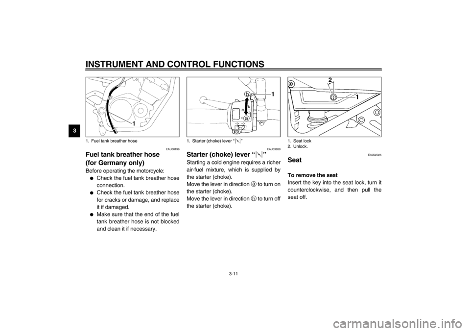
EAU00196
Fuel tank breather hose
(for Germany only) Before operating the motorcycle:�
Check the fuel tank breather hose
connection.
�
Check the fuel tank breather hose
for cracks or damage, and replace
it if damaged.
�
Make sure that the end of the fuel
tank breather hose is not blocked
and clean it if necessary.
EAU03839
Starter (choke) lever “” Starting a cold engine requires a richer
air-fuel mixture, which is supplied by
the starter (choke).
Move the lever in direction
a to turn on
the starter (choke).
Move the lever in direction
b to turn off
the starter (choke).
EAU02925
Seat To remove the seat
Insert the key into the seat lock, turn it
counterclockwise, and then pull the
seat off.
1. Fuel tank breather hose
1. Starter (choke) lever “”
1. Seat lock
2. Unlock.
E_4km.book Page 11 Tuesday, August 28, 2001 9:51 AM
Page 73 of 102

batte")
PERIODIC MAINTENANCE AND MINOR REPAIR
6-30
6
EC000102
CAUTION:@ �
Always keep the battery
charged. Storing a discharged
battery can cause permanent
battery damage.
�
To charge a sealed-type (MF)
battery, a special (constant-
voltage) battery charger is re-
quired. Using a conventional
battery charger will damage the
battery. If you do not have ac-
cess to a sealed-type (MF) bat-
tery charger, have a Yamaha
dealer charge your battery.
@
EAU04359*
Replacing the fuses The main fuse and the fuse box, which
contains the fuses for the individual cir-
cuits, are located behind cowling B.
(See page 6-6 for cowling removal and
installation procedures.)
If a fuse is blown, replace it as follows.
1. Turn the key to “OFF” and turn off
the electrical circuit in question.
2. Remove the blown fuse, and then
install a new fuse of the specified
amperage.1. Fuse box
2. Main fuse
1. Headlight fuse
2. Ignition fuse
3. Clock fuse
4. Hazard fuse
5. Main fuse
6. Spare fuse (× 3)
7. Signaling system fuseSpecified fuses:
Main fuse: 30 A
Headlight fuse: 15 A
Signaling system fuse: 20 A
Ignition fuse: 10 A
Clock fuse: 10 A
Hazard fuse: 10 A
E_4km.book Page 30 Tuesday, August 28, 2001 9:51 AM
Page 75 of 102

PERIODIC MAINTENANCE AND MINOR REPAIR
6-32
6 3. Place a new headlight bulb into
position, and then secure it with
the bulb holder.
EC000105
CAUTION:_ Do not touch the glass part of the
headlight bulb to keep it free from
oil, otherwise the transparency of
the glass, the luminosity of the bulb,
and the bulb life will be adversely af-
fected. Thoroughly clean off any dirt
and fingerprints on the headlight
bulb using a cloth moistened with
alcohol or thinner. _4. Install the headlight bulb cover,
and then connect the coupler.
5. Have a Yamaha dealer adjust the
headlight beam if necessary.
EAU01623
Replacing the tail/brake light
bulb 1. Remove the tail/brake light lens by
removing the screws.
2. Remove the defective bulb by
pushing it in and turning it counter-
clockwise.
3. Insert a new bulb into the socket,
push it in, and then turn it clock-
wise until it stops.
4. Install the lens by installing the
screws.
EC000108
CAUTION:_ Do not overtighten the screws, oth-
erwise the lens may break. _
EAU03497
Replacing a turn signal light
bulb 1. Remove the turn signal light lens
by removing the screw.
2. Remove the defective bulb by
pushing it in and turning it counter-
clockwise.
3. Insert a new bulb into the socket,
push it in, and then turn it clock-
wise until it stops.
4. Install the lens by installing the
screw.
ECA00065
CAUTION:_ Do not overtighten the screw, other-
wise the lens may break. _
1. Do not touch this area.
1. Screw (× 2)
1. Screw
E_4km.book Page 32 Tuesday, August 28, 2001 9:51 AM
Page 93 of 102
SPECIFICATIONS
8-4
8
Voltage, capacity 12 V, 12 Ah
Headlight typeQuar tz bulb (halogen)
Bulb voltage, wattage × quantity
Headlight 12 V, 60/55 W × 1
Tail/brake light 12 V, 5/21 W × 1
Auxiliary light 12 V, 4 W × 1
Turn signal light 12 V, 21 W × 4
Meter lighting 12 V, 3.4 W × 4
Neutral indicator light 12 V, 3.4 W × 1
High beam indicator light 12 V, 3.4 W × 1
Oil level warning light 12 V, 3.4 W × 1
Turn signal indicator light 12 V, 3.4 W × 2
Fuel level warning light 12 V, 3.4 W × 1
Fuses
Main fuse 30 A
Signaling system fuse 20 A
Headlight fuse 15 A
Hazard fuse 10 A
Ignition fuse 10 A
Clock fuse 10 A
E_4km.book Page 4 Tuesday, August 28, 2001 9:51 AM

2. Left handlebar switches (page 3-6)
3. Starter (choke) lever (page 3-11)
4. Speedometer unit (page 3-3)
5. Tachometer (page 3-4)")

Bulb voltage, wattage × quantity
Headlight 12 V, 60/55 W × 1
Tail/brake light 12 V, 5/21 W × 1
Auxiliary ligh")