Page 13 of 104
DESCRIPTION
2-2
2
Right view (XJ600S)8. Tail/brake light
9. Storage compartment (page 3-14)
10. Seat (page 3-12)
11. Fuel tank (page 3-9)
12. Headlight (page 6-30)
13. Brake pedal (page 3-9)
E_4br.book Page 2 Wednesday, July 25, 2001 1:40 PM
Page 14 of 104
DESCRIPTION
2-3
2
Controls and instruments (XJ600S)14. Clutch lever (page 3-7)
15. Left handlebar switches (page 3-6)
16. Starter (choke) lever (page 3-12)
17. Speedometer unit (page 3-4)
18. Tachometer (page 3-5)
19. Right handlebar switches (page 3-7)
20. Brake lever (page 3-8)
21. Throttle grip (page 6-13)
22. Main switch/steering lock (page 3-1)E_4br.book Page 3 Wednesday, July 25, 2001 1:40 PM
Page 16 of 104
DESCRIPTION
2-5
2
Right view (XJ600N)9. Tail/brake light
10. Storage compartment (page 3-13)
11. Seat (page 3-12)
12. Fuel tank (page 3-9)
13. Headlight (page 6-30)
14. Brake pedal (page 3-9)
E_4br.book Page 5 Wednesday, July 25, 2001 1:40 PM
Page 17 of 104
DESCRIPTION
2-6
2
Controls and instruments (XJ600N)15. Clutch lever (page 3-7)
16. Left handlebar switches (page 3-6)
17. Starter (choke) lever (page 3-12)
18. Speedometer unit (page 3-5)
19. Tachometer (page 3-5)
20. Right handlebar switches (page 3-7)
21. Brake lever (page 3-8)
22. Throttle grip (page 6-13)
23. Main switch (page 3-1)
E_4br.book Page 6 Wednesday, July 25, 2001 1:40 PM
Page 19 of 104

3
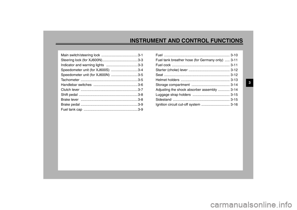
INSTRUMENT AND CONTROL FUNCTIONS
Main switch/steering lock ..................................... 3-1
Steering lock (for XJ600N).................................... 3-3
Indicator and warning lights ................................ 3-3
Speedometer unit (for XJ600S) ........................... 3-4
Speedometer unit (for XJ600N) ........................... 3-5
Tachometer .......................................................... 3-5
Handlebar switches ............................................. 3-6
Clutch lever .......................................................... 3-7
Shift pedal ............................................................ 3-8
Brake lever .......................................................... 3-8
Brake pedal .......................................................... 3-9
Fuel tank cap ....................................................... 3-9Fuel ................................................................... 3-10
Fuel tank breather hose (for Germany only) ..... 3-11
Fuel cock ........................................................... 3-11
Starter (choke) lever .......................................... 3-12
Seat ................................................................... 3-12
Helmet holders .................................................. 3-13
Storage compartment ....................................... 3-14
Adjusting the shock absorber assembly ............ 3-14
Luggage strap holders ...................................... 3-15
Sidestand .......................................................... 3-15
Ignition circuit cut-off system ............................. 3-16
E_4br.book Page 1 Wednesday, July 25, 2001 1:40 PM
Page 27 of 104
INSTRUMENT AND CONTROL FUNCTIONS
3-8
3
EAU00157
Shift pedal The shift pedal is located on the left
side of the engine and is used in com-
bination with the clutch lever when
shifting the gears of the 6-speed con-
stant-mesh transmission equipped on
this motorcycle.
EAU00160
Brake lever The brake lever is located at the right
handlebar grip. To apply the front
brake, pull the lever toward the handle-
bar grip.The brake lever is equipped with a po-
sition adjusting nut. To adjust the dis-
tance between the brake lever and the
handlebar grip, turn the adjusting nut
while holding the lever pushed away
from the handlebar grip. Make sure that
the mark “” on the adjusting nut is
aligned with the mark “” on the brake
lever.
1. Shift pedal
1. Brake lever
2. Brake lever position adjusting nut
1. Brake lever position adjusting nut
2. Properly aligned marks
E_4br.book Page 8 Wednesday, July 25, 2001 1:40 PM
Page 28 of 104
INSTRUMENT AND CONTROL FUNCTIONS
3-9
3
EAU00162
Brake pedal The brake pedal is on the right side of
the motorcycle. To apply the rear
brake, press down on the brake pedal.
EAU02935
Fuel tank cap To open the fuel tank cap
Open the fuel tank cap lock cover, in-
sert the key into the lock, and then turn
it 1/4 turn clockwise. The lock will be re-
leased and the fuel tank cap can be
opened.
To close the fuel tank cap
1. Push the fuel tank cap into position
with the key inserted in the lock.
2. Turn the key counterclockwise to
the original position, remove it,
and then close the lock cover.
NOTE:@ The fuel tank cap cannot be closed un-
less the key is in the lock. In addition,
the key cannot be removed if the cap is
not properly closed and locked. @
EWA00025
WARNING
@ Make sure that the fuel tank cap is
properly closed before riding. @
1. Brake pedal
1. Fuel tank cap lock cover
2. Unlock.
E_4br.book Page 9 Wednesday, July 25, 2001 1:40 PM
Page 38 of 104

4-1
4
EAU01114
4-PRE-OPERATION CHECKSThe condition of a vehicle is the owner’s responsibility. Vital components can start to deteriorate quickly and unexpectedly,
even if the vehicle remains unused (for example, as a result of exposure to the elements). Any damage, fluid leakage or loss
of tire air pressure could have serious consequences. Therefore, it is very important, in addition to a thorough visual inspec-
tion, to check the following points before each ride.
EAU03439
Pre-operation check list
ITEM CHECKS PAGE
Front brake
Check operation, fluid level and fluid leakage.
Fill with DOT 4 brake fluid if necessary.6-19–6-21
Rear brake6-18–6-21
ClutchCheck operation, condition and free play.
Adjust if necessary.6-17–6-18
Throttle grip and housing
Make sure that operation is smooth.
Check free play.
If necessary, have Yamaha dealer make adjustment or lubricate.
6-13, 6-24
Engine oilCheck oil level.
Fill with oil if necessary.6-7–6-10
Drive chainCheck chain slack and condition.
Adjust if necessary.6-21–6-23
Wheels and tiresCheck tire pressure, wear and damage. 6-14–6-17
Control and meter cablesCheck smooth operation.
Lubricate if necessary.6-23
Brake and shift pedal
shaftsCheck smooth operation.
Lubricate if necessary.6-24
Brake and clutch lever
pivotsCheck smooth operation.
Lubricate if necessary.6-25
Center and sidestand
pivotsCheck smooth operation.
Lubricate if necessary.6-25
E_4br.book Page 1 Wednesday, July 25, 2001 1:40 PM