Page 30 of 104

INSTRUMENT AND CONTROL FUNCTIONS
3-11
3
EAU00196
Fuel tank breather hose
(for Germany only) Before operating the motorcycle:�
Check the fuel tank breather hose
connection.
�
Check the fuel tank breather hose
for cracks or damage, and replace
it if damaged.
�
Make sure that the end of the fuel
tank breather hose is not blocked
and clean it if necessary.
EAU00207
Fuel cock The fuel cock supplies fuel from the
tank to the carburetors while also filter-
ing it.
The fuel cock lever positions are ex-
plained as follows and shown in the il-
lustrations.
ON
With the fuel cock lever in this position,
fuel flows to the carburetors when the
engine is running. Turn the fuel cock le-
ver to this position when starting the
engine and riding.RES
This indicates reserve. With the fuel
cock lever in this position, the fuel re-
serve is made available. Quickly turn
the fuel cock lever to this position if you
run out of fuel while riding, otherwise
the engine may stall and will have to be
primed (see “PRI”). After turning the
fuel cock lever to “RES”, refuel as soon
as possible and be sure to turn the fuel
cock lever back to “ON”!
1. Fuel tank breather hose
1. Arrow mark positioned over “ON”ON: Normal position
1. Arrow mark positioned over “RES”RES: Reserve position
E_4br.book Page 11 Wednesday, July 25, 2001 1:40 PM
Page 31 of 104
INSTRUMENT AND CONTROL FUNCTIONS
3-12
3
PRI
This indicates prime. With the fuel cock
lever in this position, the engine can be
“primed”. Turn the fuel cock lever to
this position when the engine has been
allowed to run out of fuel. This sends
fuel directly to the carburetors, which
will make starting easier. After the en-
gine has started, be sure to turn the le-
ver to “ON” (or “RES” if you have not
refueled yet).
EAU03839
Starter (choke) lever “” Starting a cold engine requires a richer
air-fuel mixture, which is supplied by
the starter (choke).
Move the lever in direction
a to turn on
the starter (choke).
Move the lever in direction
b to turn off
the starter (choke).
EAU02925
Seat To remove the seat
Insert the key into the seat lock, turn it
counterclockwise, and then pull the
seat off.
1. Arrow mark positioned over “PRI”PRI: Prime position
1. Starter (choke) lever “”
1. Unlock.
E_4br.book Page 12 Wednesday, July 25, 2001 1:40 PM
Page 32 of 104
INSTRUMENT AND CONTROL FUNCTIONS
3-13
3
To install the seat
Insert the projections on the front of the
seat into the seat holder, push the rear
of the seat down to lock it in place, and
then remove the key.
NOTE:@ Make sure that the seat is properly se-
cured before riding. @
EAU02936
Helmet holders The helmet holders are located under
the seat.
To secure a helmet to a helmet holder
1. Remove the seat. (See page 3-12
for seat removal and installation
procedures.)
2. Attach the helmet to the helmet
holder, and then securely install
the seat.
EWA00015
WARNING
@ Never ride with a helmet attached to
a helmet holder, since the helmet
may hit objects, causing loss of
control and possibly an accident. @To release a helmet from a helmet
holder
Remove the seat, remove the helmet
from the helmet holder, and then install
the seat.
1. Projection (× 2)
2. Seat holder
1. Helmet holder (× 2)
E_4br.book Page 13 Wednesday, July 25, 2001 1:40 PM
Page 33 of 104

INSTRUMENT AND CONTROL FUNCTIONS
3-14
3
EAU01688
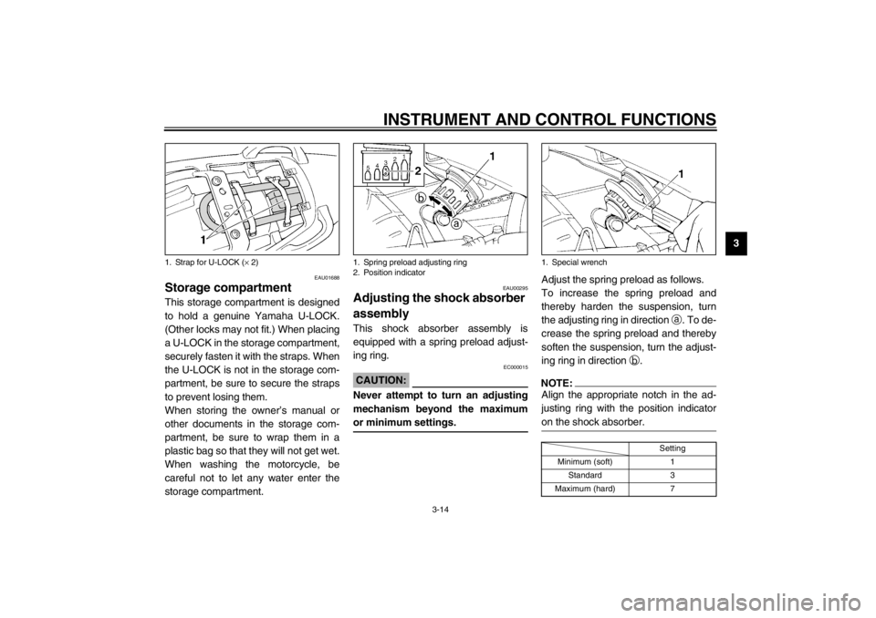
Storage compartment This storage compartment is designed
to hold a genuine Yamaha U-LOCK.
(Other locks may not fit.) When placing
a U-LOCK in the storage compartment,
securely fasten it with the straps. When
the U-LOCK is not in the storage com-
partment, be sure to secure the straps
to prevent losing them.
When storing the owner’s manual or
other documents in the storage com-
partment, be sure to wrap them in a
plastic bag so that they will not get wet.
When washing the motorcycle, be
careful not to let any water enter the
storage compartment.
EAU00295
Adjusting the shock absorber
assembly This shock absorber assembly is
equipped with a spring preload adjust-
ing ring.
EC000015
CAUTION:@ Never attempt to turn an adjusting
mechanism beyond the maximum
or minimum settings. @
Adjust the spring preload as follows.
To increase the spring preload and
thereby harden the suspension, turn
the adjusting ring in direction
a. To de-
crease the spring preload and thereby
soften the suspension, turn the adjust-
ing ring in direction
b.NOTE:@ Align the appropriate notch in the ad-
justing ring with the position indicator
on the shock absorber. @CI-10E
1. Strap for U-LOCK (× 2)
1. Spring preload adjusting ring
2. Position indicator
1. Special wrench
Setting
Minimum (soft) 1
Standard 3
Maximum (hard) 7
E_4br.book Page 14 Wednesday, July 25, 2001 1:40 PM
Page 64 of 104

PERIODIC MAINTENANCE AND MINOR REPAIR
6-17
6
EAU03773
Cast wheels To maximize the performance, durabil-
ity, and safe operation of your motor-
cycle, note the following points
regarding the specified wheels.�
The wheel rims should be checked
for cracks, bends or warpage be-
fore each ride. If any damage is
found, have a Yamaha dealer re-
place the wheel. Do not attempt
even the smallest repair to the
wheel. A deformed or cracked
wheel must be replaced.
�
The wheel should be balanced
whenever either the tire or wheel
has been changed or replaced. An
unbalanced wheel can result in
poor performance, adverse han-
dling characteristics, and a short-
ened tire life.
�
Ride at moderate speeds after
changing a tire since the tire sur-
face must first be “broken in” for it
to develop its optimal characteris-
tics.
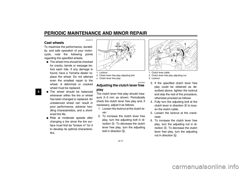
EAU00694
Adjusting the clutch lever free
play The clutch lever free play should mea-
sure 2–3 mm as shown. Periodically
check the clutch lever free play and, if
necessary, adjust it as follows.
1. Loosen the locknut at the clutch le-
ver.
2. To increase the clutch lever free
play, turn the adjusting bolt in di-
rection
a. To decrease the clutch
lever free play, turn the adjusting
bolt in direction
b.3. If the specified clutch lever free
play could be obtained as de-
scribed above, tighten the locknut
and skip the rest of the procedure,
otherwise proceed as follows.
4. Fully turn the adjusting bolt at the
clutch lever in direction
a to loos-
en the clutch cable.
5. Loosen the locknut at the crank-
case.
6. To increase the clutch lever free
play, turn the adjusting nut in di-
rection
a. To decrease the clutch
lever free play, turn the adjusting
nut in direction
b.1. Locknut
2. Clutch lever free play adjusting bolt
c. Clutch lever free play
1. Clutch lever cable
2. Clutch lever free play adjusting nut
3. Locknut
E_4br.book Page 17 Wednesday, July 25, 2001 1:40 PM
Page 65 of 104
PERIODIC MAINTENANCE AND MINOR REPAIR
6-18
6 7. Tighten the locknut at the clutch
lever and the crankcase.
EAU00712
Adjusting the brake pedal
position The top of the brake pedal should be
positioned approximately 40 mm below
the top of the footrest as shown. Peri-
odically check the brake pedal position
and, if necessary, have a Yamaha
dealer adjust it.
EW000109
WARNING
@ A soft or spongy feeling in the brake
pedal can indicate the presence of
air in the hydraulic system. If there
is air in the hydraulic system, have a
Yamaha dealer bleed the system be-
fore operating the motorcycle. Air in
the hydraulic system will diminish
the braking performance, which
may result in loss of control and an
accident.@
a. Distance between brake pedal and footrest
E_4br.book Page 18 Wednesday, July 25, 2001 1:40 PM
Page 68 of 104

PERIODIC MAINTENANCE AND MINOR REPAIR
6-21
6
�
Be careful that water does not en-
ter the brake fluid reservoir when
refilling. Water will significantly
lower the boiling point of the fluid
and may result in vapor lock.
�
Brake fluid may deteriorate paint-
ed surfaces or plastic parts. Al-
ways clean up spilled fluid
immediately.
�
As the brake pads wear, it is nor-
mal for the brake fluid level to
gradually go down. However, if the
brake fluid level goes down sud-
denly, have a Yamaha dealer
check the cause.
EAU03985*
Changing the brake fluid Have a Yamaha dealer change the
brake fluid at the intervals specified in
the NOTE after the periodic mainte-
nance and lubrication chart. In addition,
have the oil seals of the brake master
cylinders and calipers as well as the
brake hose replaced at the intervals
listed below or whenever they are dam-
aged or leaking.�
Oil seals: Replace every two
years.
�
Brake hose: Replace every four
years.
EAU00745
Drive chain slack The drive chain slack should be
checked before each ride and adjusted
if necessary.
To check the drive chain slack
1. Place the motorcycle on the
centerstand.
2. Shift the transmission into the neu-
tral position.
3. Spin the rear wheel several times
to locate the tightest portion of the
drive chain.
4. Measure the drive chain slack as
shown.a. Drive chain slack
E_4br.book Page 21 Wednesday, July 25, 2001 1:40 PM
Page 69 of 104

PERIODIC MAINTENANCE AND MINOR REPAIR
6-22
6 5. If the drive chain slack is incorrect,
adjust it as follows.
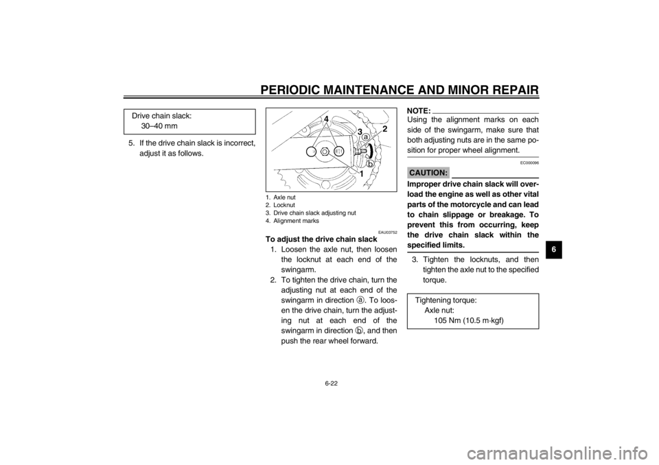
EAU03752
To adjust the drive chain slack
1. Loosen the axle nut, then loosen
the locknut at each end of the
swingarm.
2. To tighten the drive chain, turn the
adjusting nut at each end of the
swingarm in direction
a. To loos-
en the drive chain, turn the adjust-
ing nut at each end of the
swingarm in direction
b, and then
push the rear wheel forward.
NOTE:_ Using the alignment marks on each
side of the swingarm, make sure that
both adjusting nuts are in the same po-
sition for proper wheel alignment. _
EC000096
CAUTION:_ Improper drive chain slack will over-
load the engine as well as other vital
parts of the motorcycle and can lead
to chain slippage or breakage. To
prevent this from occurring, keep
the drive chain slack within the
specified limits. _3. Tighten the locknuts, and then
tighten the axle nut to the specified
torque. Drive chain slack:
30–40 mm
1. Axle nut
2. Locknut
3. Drive chain slack adjusting nut
4. Alignment marks
Tightening torque:
Axle nut:
105 Nm (10.5 m·kgf)
E_4br.book Page 22 Wednesday, July 25, 2001 1:40 PM