Page 478 of 694
5 - 4
CHAS
FRONT WHEEL AND REAR WHEEL
EC514200
Wheel axle
1. Measure:
�
Wheel axle bends
Out of specification
→
Replace.
Use the dial gauge
1
.
NOTE:
The bending value is shown by one half of the
dial gauge reading.
WARNING
Do not attempt to straighten a bent axle.
Wheel axle bending limit:
0.5 mm (0.020 in)
EC594200
Brake disc
1. Measure:
�
Brake disc deflection (only rear brake
disc)
Use the dial gauge
1
.
Out of specification
→
Inspect wheel
runout.
If wheel runout is in good condition,
replace the brake disc.
2. Measure:
�
Brake disc thickness
a
Out of limit
→
Replace.
Brake disc deflection limit:
Rear:
: 0.15 mm (0.006 in)
Brake disc thickness:
Front:
3.0 mm (0.12 in)
: 2.5 mm (0.10 in)
Rear:
4.0 mm (0.16 in)
: 3.5 mm (0.14 in)
Page 480 of 694

5 - 5
CHAS
FRONT WHEEL AND REAR WHEEL
EC595000
ASSEMBLY AND INSTALLATION
Front wheel
1. Install:
�
Bearing (left)
1
�
Spacer
2
�
Bearing (right)
3
�
Oil seal
4
NOTE:")
5 - 5
CHAS
FRONT WHEEL AND REAR WHEEL
EC595000
ASSEMBLY AND INSTALLATION
Front wheel
1. Install:
�
Bearing (left)
1
�
Spacer
2
�
Bearing (right)
3
�
Oil seal
4
NOTE:
�
Apply the lithium soap base grease on the
bearing and oil seal lip when installing.
�
Use a socket that matches the outside diam-
eter of the race of the bearing.
�
Left side of bearing shall be installed first.
�
Install the oil seal with its manufacture’s
marks or numbers facing outward.
CAUTION:
Do not strike the inner race of the bearing.
Contact should be made only with the outer
race.
2. Install:
�Brake disc 1
�Bolt (brake disc) 2
NOTE:
Tighten the bolts in stage, using a crisscross
pattern.
T R..12 Nm (1.2 m · kg, 8.7 ft · lb)
3. Install:
�Collar 1
NOTE:
�Apply the lithium soap base grease on the oil
seal lip.
�Install the collar with their projection a fac-
ing the wheel.
4. Install:
�Trip meter gear unit 1
NOTE:
Make sure the two projections a in the wheel
hub are meshed with the two slots b in the trip
meter gear unit.b a1
Page 482 of 694
5 - 6
CHASFRONT WHEEL AND REAR WHEEL
5. Install:
�Wheel
NOTE:
�Install the brake disc between the brake
pads correctly.
�Make sure that the projections a in the trip
meter gear unit fits over the stopper b on
the front fork outer tube.
6. Install:
�Wheel axle 1
NOTE:
Apply the lithium soap base grease on the
wheel axle.
7. Install:
�Nut (wheel axle) 1
T R..105 Nm (10.5 m · kg, 75 ft · lb)
8. Tighten:
�Bolt (axle holder) 1
NOTE:
Before tightening the bolt, fit the wheel axle to
the axle holder by stroking the front fork sev-
eral times with the front brake applied.
T R..23 Nm (2.3 m · kg, 17 ft · lb)
Page 484 of 694
5 - 7
CHASFRONT WHEEL AND REAR WHEEL
9. Install:
�Brake hose 1
To brake hose holder 2.
NOTE:
Before tightening the bolt (brake hose holder),
pass the brake hose in front of the axle boss
a, then fit it into the hose groove b so that the
brake hose does not contact the nut (wheel
axle).
T R..10 Nm (1.0 m · kg, 7.2 ft · lb)
10. Install:
�Brake hose cover 1
�Washer 2
�Bolt [brake hose cover (M8)] 3
�Bolt [brake hose cover (M6)] 4
T R..16 Nm (1.6 m · kg, 11 ft · lb)
T R..7 Nm (0.7 m · kg, 5.1 ft · lb)
11. Install:
�Trip meter cable 11
Page 486 of 694
5 - 8
CHAS
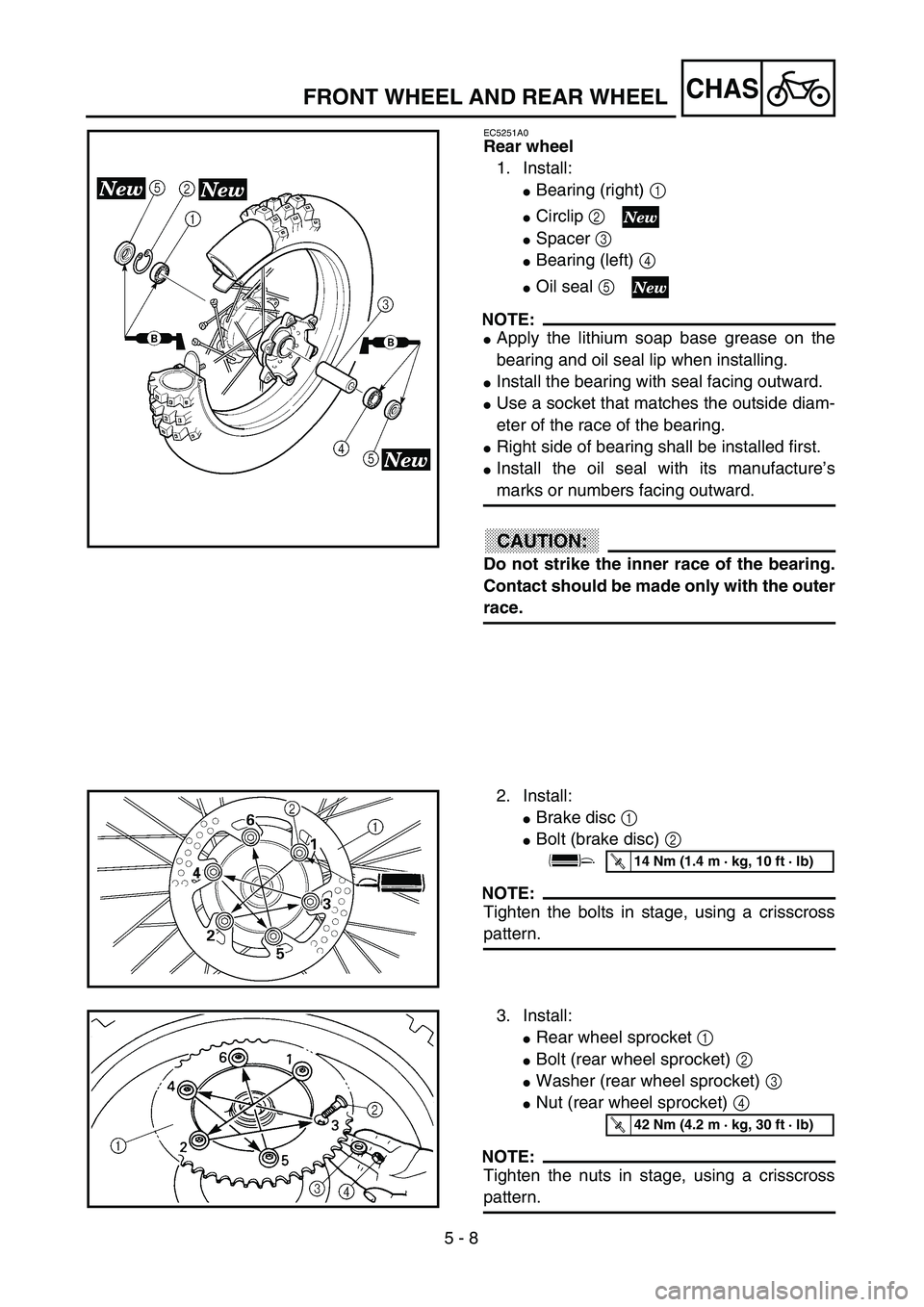
EC5251A0
Rear wheel
1. Install:
�Bearing (right) 1
�Circlip 2
�Spacer 3
�Bearing (left) 4
�Oil seal 5
NOTE:
�Apply the lithium soap base grease on the
bearing and oil seal lip when installing.
�Install the bearing with seal facing outward.
�Use a socket that matches the outside diam-
eter of the race of the bearing.
�Right side of bearing shall be installed first.
�Install the oil seal with its manufacture’s
marks or numbers facing outward.
CAUTION:
Do not strike the inner race of the bearing.
Contact should be made only with the outer
race.
2. Install:
�Brake disc 1
�Bolt (brake disc) 2
NOTE:
Tighten the bolts in stage, using a crisscross
pattern.
T R..14 Nm (1.4 m · kg, 10 ft · lb)
3. Install:
�Rear wheel sprocket 1
�Bolt (rear wheel sprocket) 2
�Washer (rear wheel sprocket) 3
�Nut (rear wheel sprocket) 4
NOTE:
Tighten the nuts in stage, using a crisscross
pattern.
T R..42 Nm (4.2 m · kg, 30 ft · lb)
FRONT WHEEL AND REAR WHEEL
Page 488 of 694
5 - 9
CHASFRONT WHEEL AND REAR WHEEL
4. Install:
�Collar 1
NOTE:
Apply the lithium soap base grease on the oil
seal lip.
5. Install:
�Wheel
NOTE:
Install the brake disc 1 between the brake
pads 2 correctly.
6. Install:
�Drive chain 1
NOTE:
Push the wheel 2 forward and install the drive
chain.
7. Install:
�Left drive chain puller 1
�Wheel axle 2
NOTE:
�Install the left drive chain puller, and insert
the wheel axle from left side.
�Apply the lithium soap base grease on the
wheel axle.
8. Install:
�Right drive chain puller 1
�Washer 2
�Nut (wheel axle) 3
NOTE:
Temporarily tighten the nut (wheel axle) at this
point.
Page 492 of 694
5 - 11
CHASFRONT BRAKE AND REAR BRAKE
EC5A0000
FRONT BRAKE AND REAR BRAKE
EC5A8000
FRONT BRAKE
Extent of removal:1 Brake hose removal2 Brake caliper removal
3 Brake master cylinder removal
Extent of removal Order Part name Q’ty Remarks
Preparation for removalFRONT BRAKE REMOVAL
Hold the machine by placing the
suitable stand under the engine.
Drain the brake fluid.
WARNING
Support the machine securely so there is nodanger of it falling over.
Refer to “REMOVAL POINTS”.
1 Brake hose cover 1
2 Brake hose holder 1
3 Bolt (brake hose holder) 2 Only loosening.
4 Union bolt 2
5 Brake hose 1
6 Pad pin plug 1 Remove when loosening the pad pin.
7 Pad pin 1 Loosen when disassembling the caliper.
8 Brake caliper 1
9 Brake lever 1
10 Brake master cylinder bracket 1
11 Brake master cylinder 1
2
3
1
3
2
Page 494 of 694
5 - 12
CHAS
EC5A8100
REAR BRAKE
Extent of removal:1 Brake caliper removal2 Brake hose removal
3 Brake master cylinder removal
Extent of removal Order Part name Q’ty Remarks
Preparation for removalREAR BRAKE REMOVAL
Hold the machine by placing the
suitable stand under the engine.
WARNING
Support the machine securely so there is nodanger of it falling over.
Rear wheel Refer to “FRONT WHEEL AND REAR
WHEEL” section.
Drain the brake fluid. Refer to “REMOVAL POINTS”.
1 Pad pin plug 1 Remove when loosening the pad pin.
2 Pad pin 1 Loosen when disassembling the caliper.
3 Brake caliper 1
4 Brake hose holder 2
5 Union bolt 2
6 Brake hose 1
7 Brake pedal 1
8 Reservoir tank 1
9 Reservoir hose 1
10Brake master cylinder
1
3
1
321
FRONT BRAKE AND REAR BRAKE


 5 - 11
CHASFRONT BRAKE AND REAR BRAKE
EC5A0000
FRONT BRAKE AND REAR BRAKE
EC5A8000
FRONT BRAKE
Extent of removal:1 Brake hose removal2 Brake caliper removal
3 Brake master cylinder removal
Extent of r")
 5 - 12
CHAS
EC5A8100
REAR BRAKE
Extent of removal:1 Brake caliper removal2 Brake hose removal
3 Brake master cylinder removal
Extent of removal Order Part name Q’ty Remarks
Preparation for removalRE")