Page 200 of 694
 3 - 17
INSP
ADJ
ENGINE OIL REPLACEMENT
7. If the oil filter is to be replaced during this
oil change, remove the following parts
and reinstall them.
8. Install:
�Copper washer 1
�Oil strainer (frame)")
3 - 17
INSP
ADJ
ENGINE OIL REPLACEMENT
7. If the oil filter is to be replaced during this
oil change, remove the following parts
and reinstall them.
8. Install:
�Copper washer 1
�Oil strainer (frame) 2
�Oil hose 3
�Bolt (oil hose) 4
�Oil hose clamp 5
�Lower engine bracket
9. Install:
�Copper washer
�Oil filter element drain bolt
�Crankcase oil drain bolt
�Frame oil drain bolt
10. Fill:
�Engine oil
11. Check:
�Oil leakage
12. Install:
�Oil tank cap
13. Check:
�Engine oil level Replacement steps:
�Remove the oil filter element cover 1 and
oil filter element 2.
�Check the O-rings 3, if cracked or dam-
aged, replace them with a new one.
�Install the oil filter element and oil filter ele-
ment cover.
T R..
Oil filter element cover:
10 Nm (1.0 m • kg, 7.2 ft • lb)
Oil quantity:
Total amount:
1.7 L (1.50 Imp qt, 1.80 US qt)
Periodic oil change:
1.5 L (1.32 Imp qt, 1.59 US qt)
With oil filter replacement:
1.6 L (1.41 Imp qt, 1.69 US qt)
T R..90 Nm (9.0 m · kg, 65 ft · lb)
T R..10 Nm (1.0 m · kg, 7.2 ft · lb)
T R..2 Nm (0.2 m · kg, 1.4 ft · lb)
T R..10 Nm (1.0 m · kg, 7.2 ft · lb)
T R..10 Nm (1.0 m · kg, 7.2 ft · lb)
T R..20 Nm (2.0 m · kg, 14 ft · lb)
T R..23 Nm (2.3 m · kg, 17 ft · lb)
Page 202 of 694
 3 - 18
INSP
ADJ
OIL PRESSURE INSPECTION
1. Check:
�Oil pressure
Checking steps:
�Slightly loosen the oil pressure check bolt
1.
�Start the engine and keep it idling until oil
starts to seep from the o")
3 - 18
INSP
ADJ
OIL PRESSURE INSPECTION
1. Check:
�Oil pressure
Checking steps:
�Slightly loosen the oil pressure check bolt
1.
�Start the engine and keep it idling until oil
starts to seep from the oil pressure check
bolt. If no oil comes out after one minute,
turn the engine off so it will not seize.
�Check oil passages and oil pump for dam-
age or leakage.
�Start the engine after solving the prob-
lem(s) and recheck the oil pressure.
�Tighten the oil pressure check bolt.
T R..
Oil pressure check bolt:
10 Nm (1.0 m • kg, 7.2 ft • lb)
PILOT SCREW ADJUSTMENT
1. Adjust:
�Pilot screw 1
* For EUROPE
** For CDN, ZA, AUS and NZAdjustment steps:
NOTE:
To optimize the fuel flow at a smaller throttle
opening, each machine’s pilot screw has
been individually set at the factory. Before
adjusting the pilot screw, turn it in fully and
count the number of turns. Record this num-
ber as the factory-set number of turns out.
�Turn in the pilot screw until it is lightly
seated.
�Turn out the pilot screw by the factory-set
number of turns.
Pilot screw:
2 turns out
* 1 turn out
** 1-1/8 turns out
(example)
OIL PRESSURE INSPECTION/
PILOT SCREW ADJUSTMENT
Page 236 of 694
3 - 34
INSP
ADJ
DRIVE CHAIN INSPECTION
5. Check:
�Drive chain stiffness a
Clean and oil the drive chain and hold
as illustrated.
Stiff → Replace the drive chain.
6. Install:
�Chain joint 1
�O-ring 2
�Drive chain 3
NOTE:
When installing the drive chain, apply the lith-
ium soap base grease on the chain joint and
O-rings.
7. Install:
�Link plate 4
NOTE:
�Press the link plate onto the chain joint using
a drive chain rivetter 5.
�Rivet the end of the chain joint using a drive
chain rivetter 6.
�After rivetting the chain joint, make sure its
movement is smooth.
8. Lubricate:
�Drive chain
Drive chain lubricant:
SAE 10W-30 motor oil or suit-
able chain lubricants
Page 406 of 694
4 - 69
ENGOIL PUMP
INSPECTION
Oil pump
1. Inspect:
�Oil pump drive gear 1
�Oil pump drive shaft 2
�Rotor housing 3
�Oil pump cover 4
Cracks/wear/damage → Replace.
1
32
4
2. Measure:
�Tip clearance a
(between the inner rotor 1 and outer
rotor 2)
�Side clearance b
(between the outer rotor 2 and rotor
housing 3)
�Housing and rotor clearance c
(between the rotor housing 3 and
rotors 1 2)
Out of specification → Replace the oil
pump assembly.
Tip clearance a:
0.12 mm or less
(0.0047 in or less)
: 0.20 mm (0.008 in)
Side clearance b:
0.09 ~ 0.17 mm (0.0035 ~ 0.0067 in)
: 0.24 mm (0.009 in)
Housing and rotor clearance c:
0.03 ~ 0.10 mm (0.0012 ~ 0.0039 in)
: 0.17 mm (0.0067 in)
3. Check:
�Unsmooth → Repeat steps #1 and #2
or replace the defective parts.
Page 458 of 694
4 - 95
ENGCRANKCASE AND CRANKSHAFT
2. Check:
�Shifter operation
�Transmission operation
Unsmooth operation → Repair.
3. Install:
�Oil strainer 1
�Bolt (oil strainer) 2
T R..10 Nm (1.0 m · kg, 7.2 ft · lb)
4. Apply:
�Sealant
On the right crankcase 1.
NOTE:
Clean the contacting surface of left and right
crankcase before applying the sealant.
5. Install:
�Dowel pin 1
�O-ring 2
�Right crankcase
To left crankcase.
NOTE:
�Fit the right crankcase onto the left crank-
case. Tap lightly on the case with soft ham-
mer.
�When installing the crankcase, the connect-
ing rod should be positioned at TDC (top
dead center).
Quick gasket®:
ACC-QUICK-GS-KT
YAMAHA Bond No. 1215:
90890-85505
Page 460 of 694
4 - 96
ENGCRANKCASE AND CRANKSHAFT
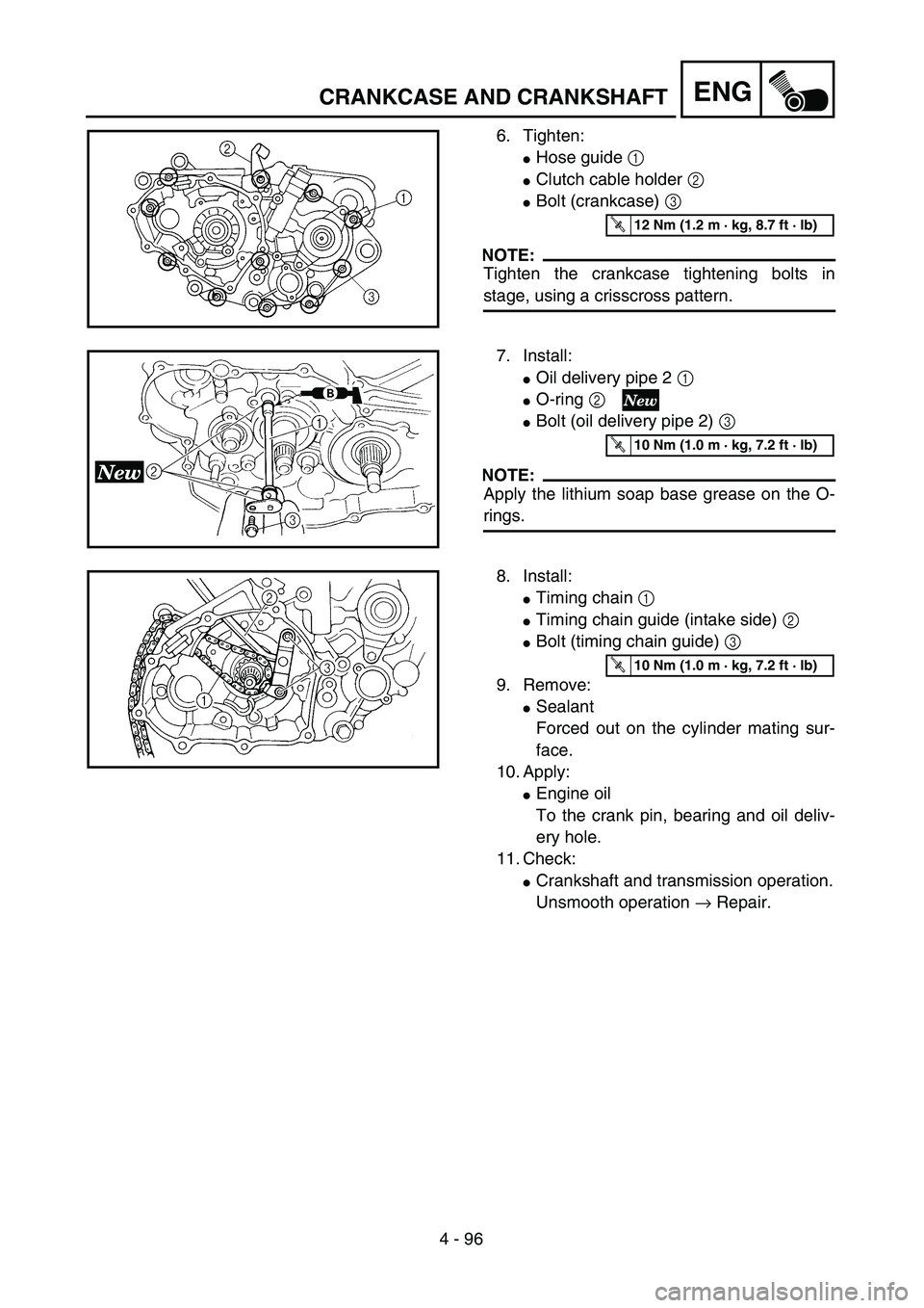
6. Tighten:
�Hose guide 1
�Clutch cable holder 2
�Bolt (crankcase) 3
NOTE:
Tighten the crankcase tightening bolts in
stage, using a crisscross pattern.
T R..12 Nm (1.2 m · kg, 8.7 ft · lb)
7. Install:
�Oil delivery pipe 2 1
�O-ring 2
�Bolt (oil delivery pipe 2) 3
NOTE:
Apply the lithium soap base grease on the O-
rings.
T R..10 Nm (1.0 m · kg, 7.2 ft · lb)
8. Install:
�Timing chain 1
�Timing chain guide (intake side) 2
�Bolt (timing chain guide) 3
9. Remove:
�Sealant
Forced out on the cylinder mating sur-
face.
10. Apply:
�Engine oil
To the crank pin, bearing and oil deliv-
ery hole.
11. Check:
�Crankshaft and transmission operation.
Unsmooth operation → Repair.
T R..10 Nm (1.0 m · kg, 7.2 ft · lb)
Page 466 of 694
4 - 99
ENGTRANSMISSION, SHIFT CAM AND SHIFT FORK
EC4H4810
Shift fork, shift cam and segment
1. Inspect:
�Shift fork 1
Wear/damage/scratches → Replace.
2. Inspect:
�Shift cam 1
�Segment 2
Wear/damage → Replace.
3. Check:
�Shift fork movement
Unsmooth operation → Replace shift
fork.
NOTE:
For a malfunctioning shift fork, replace not only
the shift fork itself but the two gears each adja-
cent to the shift fork.
EC4H5000
ASSEMBLY AND INSTALLATION
Transmission
1. Install:
�5th pinion gear (27T) 1
�3rd pinion gear (21T) 2
�Collar 3
�4th pinion gear (24T) 4
�2nd pinion gear (16T) 5
To main axle 6.
NOTE:
�Apply the molybdenum disulfide oil on the
4th and 5th pinion gears inner circumference
and on the end surface.
�Apply the molybdenum disulfide oil on the
2nd and 3rd pinion gears inner circumfer-
ence.
Page 470 of 694
4 - 101
ENGTRANSMISSION, SHIFT CAM AND SHIFT FORK
5. Install:
�Shift fork 1 (L) 1
�Shift fork 2 (C) 2
�Shift fork 3 (R) 3
�Shift cam 4
To main axle and drive axle.
NOTE:
�Apply the molybdenum disulfide oil on the
shift fork grooves.
�Mesh the shift fork #1 (L) with the 4th wheel
gear 5 and #3 (R) with the 5th wheel gear
7 on the drive axle.
�Mesh the shift fork #2 (C) with the 3rd pinion
gear 6 on the main axle.
6. Install:
�Transmission assembly 1
To left crankcase 2.
NOTE:
Apply the engine oil on the bearings and guide
bars.
7. Check:
�Shifter operation
�Transmission operation
Unsmooth operation → Repair.