Page 200 of 694

3 - 17
INSP
ADJ
ENGINE OIL REPLACEMENT
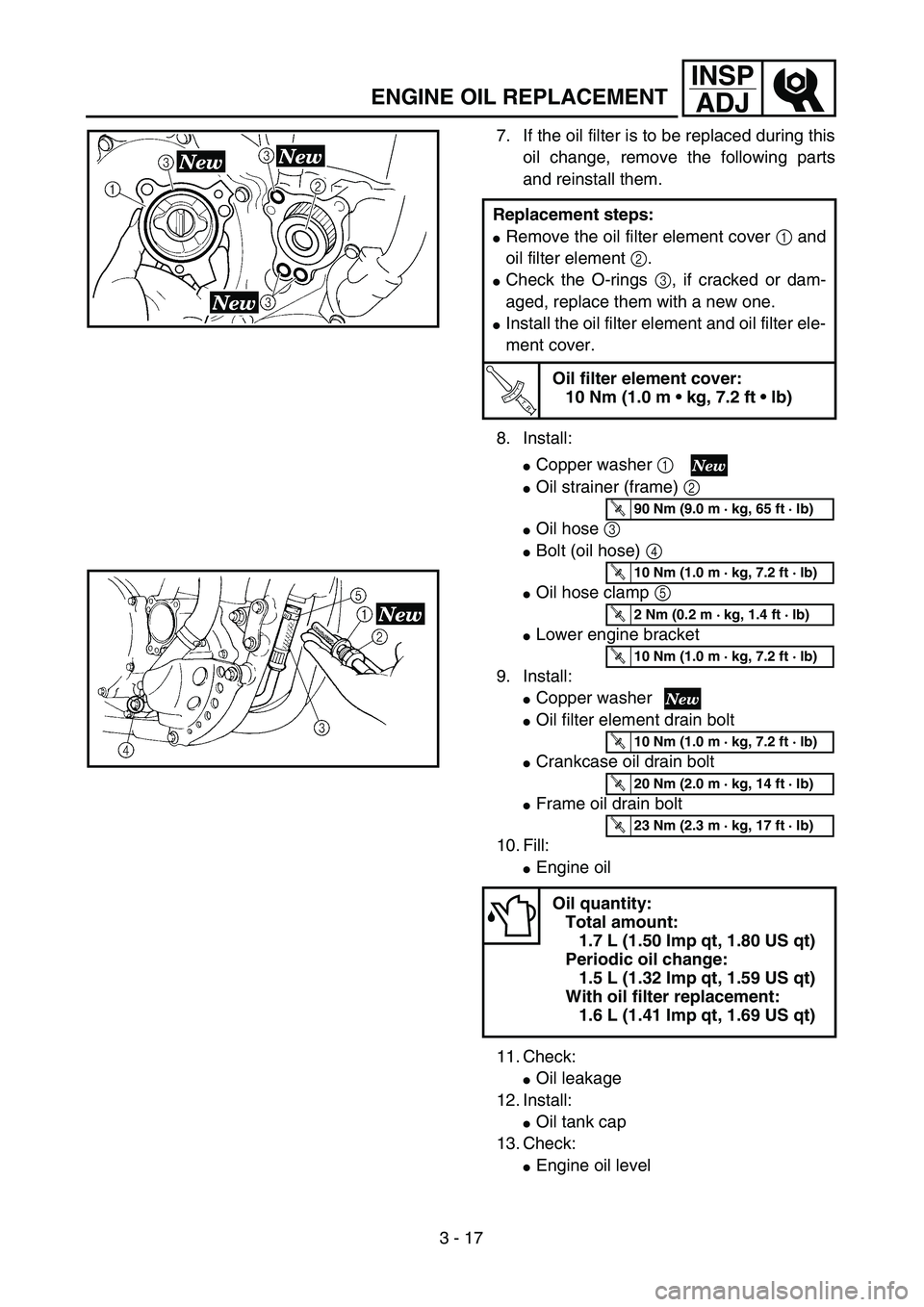
7. If the oil filter is to be replaced during this
oil change, remove the following parts
and reinstall them.
8. Install:
�Copper washer 1
�Oil strainer (frame) 2
�Oil hose 3
�Bolt (oil hose) 4
�Oil hose clamp 5
�Lower engine bracket
9. Install:
�Copper washer
�Oil filter element drain bolt
�Crankcase oil drain bolt
�Frame oil drain bolt
10. Fill:
�Engine oil
11. Check:
�Oil leakage
12. Install:
�Oil tank cap
13. Check:
�Engine oil level Replacement steps:
�Remove the oil filter element cover 1 and
oil filter element 2.
�Check the O-rings 3, if cracked or dam-
aged, replace them with a new one.
�Install the oil filter element and oil filter ele-
ment cover.
T R..
Oil filter element cover:
10 Nm (1.0 m • kg, 7.2 ft • lb)
Oil quantity:
Total amount:
1.7 L (1.50 Imp qt, 1.80 US qt)
Periodic oil change:
1.5 L (1.32 Imp qt, 1.59 US qt)
With oil filter replacement:
1.6 L (1.41 Imp qt, 1.69 US qt)
T R..90 Nm (9.0 m · kg, 65 ft · lb)
T R..10 Nm (1.0 m · kg, 7.2 ft · lb)
T R..2 Nm (0.2 m · kg, 1.4 ft · lb)
T R..10 Nm (1.0 m · kg, 7.2 ft · lb)
T R..10 Nm (1.0 m · kg, 7.2 ft · lb)
T R..20 Nm (2.0 m · kg, 14 ft · lb)
T R..23 Nm (2.3 m · kg, 17 ft · lb)
Page 202 of 694

3 - 18
INSP
ADJ
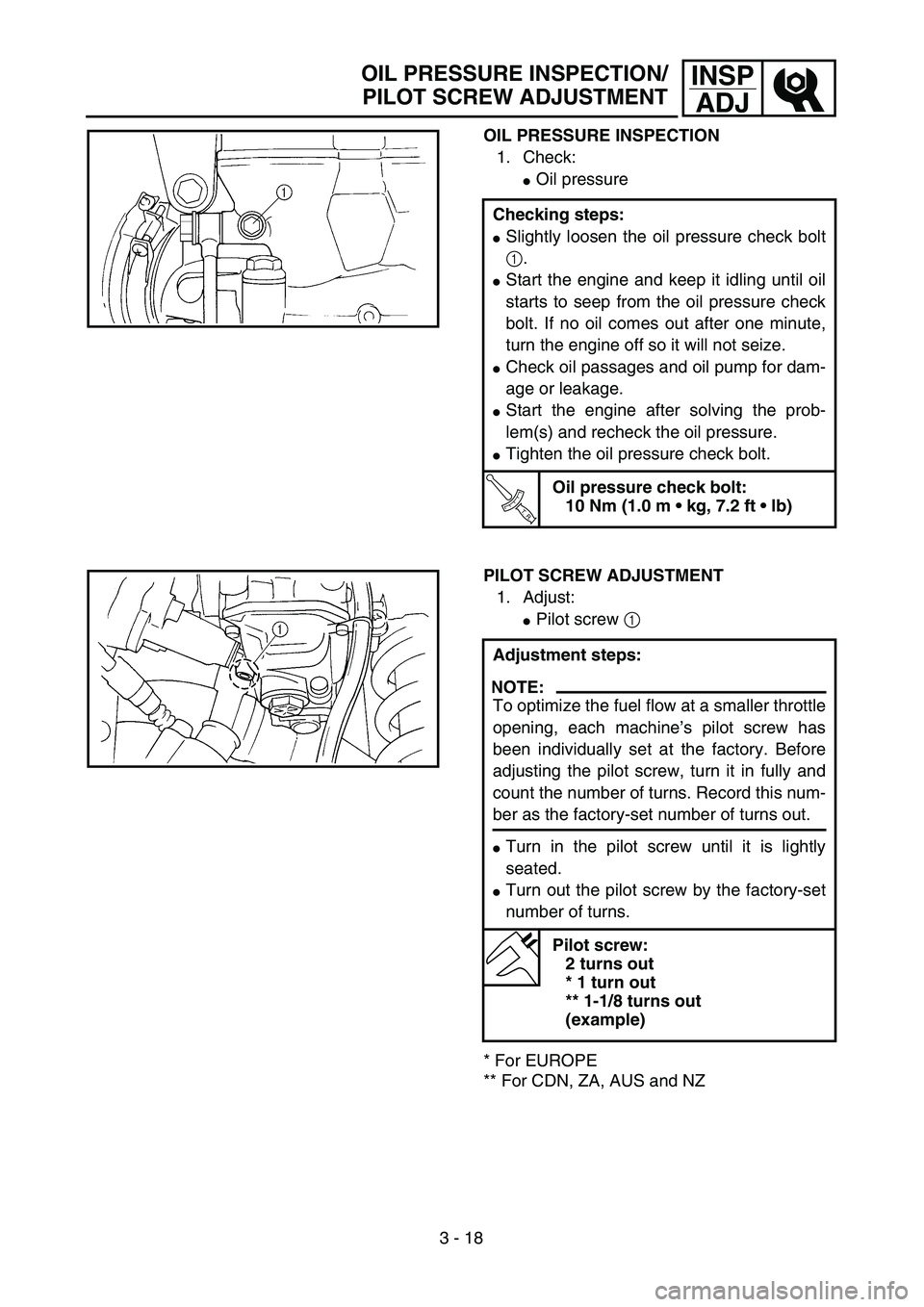
OIL PRESSURE INSPECTION
1. Check:
�Oil pressure
Checking steps:
�Slightly loosen the oil pressure check bolt
1.
�Start the engine and keep it idling until oil
starts to seep from the oil pressure check
bolt. If no oil comes out after one minute,
turn the engine off so it will not seize.
�Check oil passages and oil pump for dam-
age or leakage.
�Start the engine after solving the prob-
lem(s) and recheck the oil pressure.
�Tighten the oil pressure check bolt.
T R..
Oil pressure check bolt:
10 Nm (1.0 m • kg, 7.2 ft • lb)
PILOT SCREW ADJUSTMENT
1. Adjust:
�Pilot screw 1
* For EUROPE
** For CDN, ZA, AUS and NZAdjustment steps:
NOTE:
To optimize the fuel flow at a smaller throttle
opening, each machine’s pilot screw has
been individually set at the factory. Before
adjusting the pilot screw, turn it in fully and
count the number of turns. Record this num-
ber as the factory-set number of turns out.
�Turn in the pilot screw until it is lightly
seated.
�Turn out the pilot screw by the factory-set
number of turns.
Pilot screw:
2 turns out
* 1 turn out
** 1-1/8 turns out
(example)
OIL PRESSURE INSPECTION/
PILOT SCREW ADJUSTMENT
Page 212 of 694

3 - 23
INSP
ADJ
VALVE CLEARANCE INSPECTION AND ADJUSTMENT
�Locate the rounded-off value and the
measured valve clearance in the chart
“PAD SELECTION TABLE”. The field
where these two coordinates intersect
shows the new pad number to use.
NOTE:
Use the new pad number only as a guide
when verifying the valve clearance adjust-
ment.
�Install the new pads 7 and the valve lift-
ers 8.
NOTE:
�Apply the engine oil on the valve lifters.
�Apply the molybdenum disulfied oil on the
valve stem ends.
�Valve lifter must turn smoothly when
rotated with a finger.
�Be careful to reinstall valve lifters and
pads in their original place.
�Install the decompression shaft 9, copper
washer 0, bolt (decompression shaft) A,
guide B, bolt (guide) C and decompres-
sion cable D.
NOTE:
Apply the engine oil on the decompression
shaft.
T R..
Bolt (decompression shaft):
7 Nm (0.7 m • kg, 5.1 ft • lb)
Bolt (guide):
10 Nm (1.0 m • kg, 7.2 ft • lb)
�Install the camshafts (exhaust and intake).
Refer to “CAMSHAFTS” section in the
CHAPTER 4.
Page 236 of 694
3 - 34
INSP
ADJ
DRIVE CHAIN INSPECTION
5. Check:
�Drive chain stiffness a
Clean and oil the drive chain and hold
as illustrated.
Stiff → Replace the drive chain.
6. Install:
�Chain joint 1
�O-ring 2
�Drive chain 3
NOTE:
When installing the drive chain, apply the lith-
ium soap base grease on the chain joint and
O-rings.
7. Install:
�Link plate 4
NOTE:
�Press the link plate onto the chain joint using
a drive chain rivetter 5.
�Rivet the end of the chain joint using a drive
chain rivetter 6.
�After rivetting the chain joint, make sure its
movement is smooth.
8. Lubricate:
�Drive chain
Drive chain lubricant:
SAE 10W-30 motor oil or suit-
able chain lubricants
Page 240 of 694

3 - 36
INSP
ADJFRONT FORK INSPECTION/
FRONT FORK OIL SEAL AND DUST SEAL CLEANING/
FRONT FORK INTERNAL PRESSURE RELIEVING
EC36C000
FRONT FORK INSPECTION
1. Inspect:
�Front fork smooth action
Operate the front brake and stroke the
front fork.
Unsmooth action/oil leakage → Repair
or replace.
EC36D001
FRONT FORK OIL SEAL AND DUST SEAL
CLEANING
1. Remove:
�Protector
�Dust seal 1
NOTE:
Use a thin screw driver, and be careful not to
damage the inner fork tube and dust seal.
2. Clean:
�Dust seal a
�Oil seal b
NOTE:
�Clean the dust seal and oil seal after every
run.
�Apply the lithium soap base grease on the
inner tube.
FRONT FORK INTERNAL PRESSURE
RELIEVING
NOTE:
If the front fork initial movement feels stiff during
a run, relieve the front fork internal pressure.
1. Elevate the front wheel by placing a suit-
able stand under the engine.
2. Remove the air bleed screw 1 and
release the internal pressure from the
front fork.
3. Install:
�Air bleed screw
T R..1 Nm (0.1 m · kg, 0.7 ft · lb)
Page 246 of 694

3 - 39
INSP
ADJREAR SHOCK ABSORBER INSPECTION/REAR SHOCK
ABSORBER SPRING PRELOAD ADJUSTMENT
EC36K000
REAR SHOCK ABSORBER INSPECTION
1. Inspect:
�Swingarm smooth action
Abnormal noise/unsmooth action →
Grease the pivoting points or repair the
pivoting points.
Damage/oil leakage → Replace.
EC36M013
REAR SHOCK ABSORBER SPRING
PRELOAD ADJUSTMENT
1. Elevate the rear wheel by placing the
suitable stand under the engine.
2. Remove:
�Rear frame
3. Loosen:
�Locknut 1
4. Adjust:
�Spring preload
By turning the adjuster 2.
* For EUROPE
** For AUS, NZ and ZA
NOTE:
�Be sure to remove all dirt and mud from
around the locknut and adjuster before
adjustment.
�The length of the spring (installed) changes
1.5 mm (0.06 in) per turn of the adjuster.
CAUTION:
Never attempt to turn the adjuster beyond
the maximum or minimum setting.
5. Tighten:
�Locknut
6. Install:
�Rear frame Stiffer →Increase the spring preload.
(Turn the adjuster 2 in.)
Softer →Decrease the spring preload.
(Turn the adjuster 2 out.)
Spring length (installed) a:
Standard length Extent of adjustment
244 mm (9.61 in)
* 247 mm (9.72 in)
** 243.5 mm (9.59 in)240.5 ~ 258.5 mm
(9.47 ~ 10.18 in)
T R..29 Nm (2.9 m · kg, 21 ft · lb)
Page 255 of 694

INSP
ADJ
CONTROLE DE PRESSION DES PNEUS/
CONTROLE ET SERRAGE DES RAYONS/CONTROLE DE LA ROUE
REIFENLUFTDRUCK KONTROLLIEREN/
SPEICHEN KONTROLLIEREN UND FESTZIEHEN/RÄDER KONTROLLIEREN
CONTROLLO DELLA PRESSIONE DEI PNEUMATICI/
ISPEZIONE E SERRAGGIO DEI RAGGI/ISPEZIONE DELLE RUOTE
REIFENLUFTDRUCK KONTROL-
LIEREN
1. Messen:
�Reifenluftdruck
Unvorschriftsmäßig → Ein-
stellen.
HINWEIS:
�Den Reifenluftdruck bei kalten Rei-
fen kontrollieren.
�Bei zu niedrigem Reifendruck liegt
die Reifenwulst nicht fest an, was
dazu führen kann, daß sich der
Reifen von der Felge löst.
�Ein geneigter Reifenventilschaft
deutet an, daß der Reifen ver-
rutscht ist.
�Bei geneigtem Reifenventilschaft
muß die Reifenposition berichtigt
werden.
Standard-Reifenluft-
druck
100 kPa (1,0 bar)
SPEICHEN KONTROLLIEREN
UND FESTZIEHEN
1. Kontrollieren:
�Speichen 1
Verzug/Beschädigung →
Erneuern.
Speichen locker → Nach-
spannen.
2. Festziehen:
�Speichen
HINWEIS:
Die Speichen müssen vor und nach
dem Einfahren nachgezogen wer-
den. Nach jeder Übungsfahrt bzw.
Rennen die Speichenspannung prü-
fen.
T R..3 Nm (0,3 m · kg)
RÄDER KONTROLLIEREN
1. Messen:
�Felgenschlag
Das Rad anheben und dre-
hen.
Übermäßig → Erneuern. CONTROLE DE PRESSION DES
PNEUS
1. Mesurer:
�Pression des pneus
Hors spécification → Régler.
N.B.:
�Vérifier le pneu alors qu’il est froid.
�Des butées de bourrelet lâches permet-
tent au pneu de se détacher de sa posi-
tion sur la jante lorsque la pression des
pneus est basse.
�Une tige de soupape de pneu inclinée
indique que le pneu se détache de sa
position sur la jante.
�Si la tige de soupape de pneu est incli-
née, le pneu a tendance à se détacher
de sa position. Corriger la position du
pneu.
Pression des pneus stan-
dard:
100 kPa
(1,0 kgf/cm
2, 15 psi)
CONTROLE ET SERRAGE DES
RAYONS
1. Contrôler:
�Rayons 1
Déformation/endommagement
→ Remplacer.
Rayons desserrés → Resserrer.
2. Serrer:
�Rayon
N.B.:
Ne pas oublier de retendre les rayons
avant et après le rodage. Après un entraî-
nement ou une course, contrôler si les
rayons ne sont pas détendus.
T R..3 Nm (0,3 m · kg, 2,2 ft · lb)
CONTROLE DE LA ROUE
1. Mesure:
�Voile de roue
Soulever la roue et la tourner.
Voile excessif → Remplacer.CONTROLLO DELLA PRESSIONE
DEI PNEUMATICI
1. Misurare:
�Pressione dei pneumatici
Fuori specifica → Regolare.
NOTA:
�Controllare i pneumatici a freddo.
�I fermi del tallone consentono alla
ruota di scivolare dalla sua posizione
sul cerchio quando la pressione dei
pneumatici è bassa.
�Uno stelo della valvola inclinato
indica che il pneumatico scivola dalla
sua posizione sul cerchione.
�Se lo stelo della valvola è inclinato,
indica che il pneumatico ha la ten-
denza a scivolare fuori posizione. Cor-
reggere la posizione dei pneumatici.
Pressione standard pneu-
matici:
100 kPa
(1,0 kgf/cm
2, 15 psi)
ISPEZIONE E SERRAGGIO DEI
RAGGI
1. Ispezionare:
�Raggi 1
Deformazione/danno → Sosti-
tuire.
Raggi allentati → Serrare.
2. Serrare:
�Raggi
NOTA:
Accertarsi di serrare i raggi prima e dopo
il rodaggio. Dopo un allenamento o una
gara controllare l’eventuale allentamento
dei raggi.
T R..3 Nm (0,3 m · kg, 2,2 ft · lb)
ISPEZIONE DELLE RUOTE
1. Ispezionare:
�Scentratura
Sollevare la ruota e farla girare.
Scentratura anomala → Sosti-
tuirla.
3 - 43
Page 260 of 694
3 - 46
INSP
ADJ
LUBRICATION
LUBRICATION
To ensure smooth operation of all compo-
nents, lubricate your machine during setup,
after break-in, and after every race.
1All control cable
2Clutch lever pivot
3Shift pedal pivot
4Footrest pivot
5Throttle-to-handlebar contact
6Drive chain
7Tube guide cable winding portion
8Throttle cable end
9Clutch cable end
0Decompression cable endÅUse Yamaha cable lube or equivalent on these
areas.
ıUse SAE 10W-30 motor oil or suitable chain
lubricants.
ÇLubricate the following areas with high quality,
lightweight lithium-soap base grease.
CAUTION:
Wipe off any excess grease, and avoid get-
ting grease on the brake discs.
AAA
AAB
CC