Page 30 of 114
3-14
INSTRUMENT AND CONTROL FUNCTIONS
3
To install the fuel tank cap
1. Align the match marks, insert the
fuel tank cap into the tank open-
ing, and then push down on the
cap.
2. Turn the key counterclockwise to
the original position, and then
remove it.
3. Close the lid.
EWA00028
wBe sure that the fuel tank cap is
properly installed and locked
before riding the scooter.
1
1. Match marks
EAU03753
FuelFuelMake sure that there is sufficient fuel
in the tank. Fill the fuel tank to the
bottom of the filler tube as shown.
EW000130
w8 8
Do not overfill the fuel tank,
otherwise it may overflow
when the fuel warms up and
expands.
8 8
Avoid spilling fuel on the hot
engine.
1
2
1. Filler tube
2. Fuel level
EAU00185
cCImmediately wipe off spilled fuel
with a clean, dry, soft cloth, since
fuel may deteriorate painted sur-
faces or plastic parts.
5SJ-28199-E0 1/24/02 6:14 PM Page 29
Page 32 of 114

3-16
INSTRUMENT AND CONTROL FUNCTIONS
3
EC000114
cCThe following precautions must be
observed to prevent a fire hazard
or other damages.
8 8
Use only unleaded gasoline.
The use of leaded gasoline will
cause unrepairable damage to
the catalytic converter.
8 8
Never park the scooter near
possible fire hazards such as
grass or other materials that
easily burn.
8 8
Do not allow the engine to idle
too long.
EAU03091
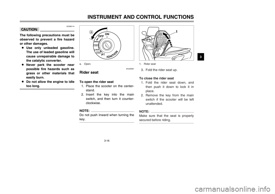
Rider seatRider seatTo open the rider seat
1. Place the scooter on the center-
stand.
2. Insert the key into the main
switch, and then turn it counter-
clockwise.NOTE:
Do not push inward when turning the
key.
IGNITION
P
LOCK
ON
OFF
OPENPUSHPUSH
a
a. Open.
3. Fold the rider seat up.
To close the rider seat
1. Fold the rider seat down, and
then push it down to lock it in
place.
2. Remove the key from the main
switch if the scooter will be left
unattended.NOTE:
Make sure that the seat is properly
secured before riding.
1
1. Rider seat
5SJ-28199-E0 1/24/02 6:14 PM Page 31
Page 33 of 114
3-17
INSTRUMENT AND CONTROL FUNCTIONS
3
EAU03096*
Adjusting the rider seatRider seat, adjustingThe rider seat can be adjusted as fol-
lows to change the riding position.
1. Open the rider seat.
1
1. Rider seat
EAU03331
Storage compartmentsStorage compartmentsFront storage compartment A
To open the storage compartment
when it is locked, insert the key in the
lock, turn it counterclockwise, and
then grasp the lock while pushing the
button in.
To open the storage compartment
when it is unlocked, simply grasp the
lock while pushing the button in.
1
2
a
1. Button
2. Lid
a. Lock.
2. Remove the bolts and collars.
3. Slide the rider seat forward or
backward to the desired position.
4. Install the collars and securely
tighten the bolts.
5. Close the rider seat.
11
2
2
1. Bolt (
×4)
2. Collar (×4)
Compartment A
5SJ-28199-E0 1/24/02 6:14 PM Page 32
Page 34 of 114
3-18
INSTRUMENT AND CONTROL FUNCTIONS
3
To lock the storage compartment,
push the lid into the original position,
insert the key in the lock, turn it clock-
wise, and then remove it.
1
2
a
1. Button
2. Lid
a. Lock.
Front storage compartment B
To open the storage compartment,
slide the lever up, and then pull on
the lever.
To close the storage compartment,
push the lid into the original position.
EWA00034
wDo not store heavy items in this
compartment.
1
2
1. Lever
2. Lid
Rear storage compartment
Two helmets can be stored in the
storage compartment under the
seats. (See page 3-16 for rider seat
opening and closing procedures.)
1
1. Rider seat
Compartment B
Compartment A
5SJ-28199-E0 1/24/02 6:14 PM Page 33
Page 77 of 114
EAU00703
Adjusting the front and rear
brake lever free playFront and rear brake lever free play, adjustingThe front and rear brake lever free
play should measure 2–5 mm as
shown. Periodically check the front
and rear brake lever free play and, if
necessary, adjust them as follows.
a b
c 1
2
1. Locknut
2. Adjusting bolt
c. Brake lever free play
6-27
PERIODIC MAINTENANCE AND MINOR REPAIR
6
FRONT
8Ride at moderate speeds after
changing a tire since the tire sur-
face must first be “broken in” for
it to develop its optimal charac-
teristics.
1. Loosen the locknut at the brake
lever.
2. To increase the brake lever free
play, turn the adjusting bolt in
direction a. To decrease the
brake lever free play, turn the
adjusting bolt in direction b.
3. Tighten the locknut.
EW000101
wIf proper adjustment cannot be
obtained as described, have a
Yamaha dealer make this adjust-
ment.
1
c
a
b
2
1. Locknut
2. Adjusting bolt
c. Brake lever free playREAR
5SJ-28199-E0 1/24/02 6:14 PM Page 76
Page 80 of 114

6-30
PERIODIC MAINTENANCE AND MINOR REPAIR
6 8Refill with the same type of brake
fluid. Mixing fluids may result in a
harmful chemical reaction and
lead to poor braking perfor-
mance.
8Be careful that water does not
enter the brake fluid reservoir
when refilling. Water will signifi-
cantly lower the boiling point of
the fluid and may result in vapor
lock.
8Brake fluid may deteriorate paint-
ed surfaces or plastic parts.
Always clean up spilled fluid
immediately.
8As the brake pads wear, it is nor-
mal for the brake fluid level to
gradually go down. However, if
the brake fluid level goes down
suddenly, have a Yamaha dealer
check the cause.
EAU03976
Changing the brake fluidBrake fluid, changingHave a Yamaha dealer change the
brake fluid at the intervals specified in
the NOTE after the periodic mainte-
nance and lubrication chart. In addi-
tion, have the oil seals of the master
cylinders and calipers as well as the
brake hoses replaced at the intervals
listed below or whenever they are
damaged or leaking.
8Oil seals: Replace every two
years.
8Brake hoses: Replace every four
years.
EAU02962
Checking and lubricating the
cablesCables, checking and lubricatingThe operation of all control cables
and the condition of the cables
should be checked before each ride,
and the cables and cable ends
should be lubricated if necessary. If a
cable is damaged or does not move
smoothly, have a Yamaha dealer
check or replace it.
EW000112
wDamage to the outer sheath may
interfere with proper cable opera-
tion and will cause the inner cable
to rust. Replace a damaged cable
as soon as possible to prevent
unsafe conditions.
Recommended lubricant:
Engine oil
5SJ-28199-E0 1/24/02 6:14 PM Page 79
Page 86 of 114

6-36
PERIODIC MAINTENANCE AND MINOR REPAIR
6
EAU04110
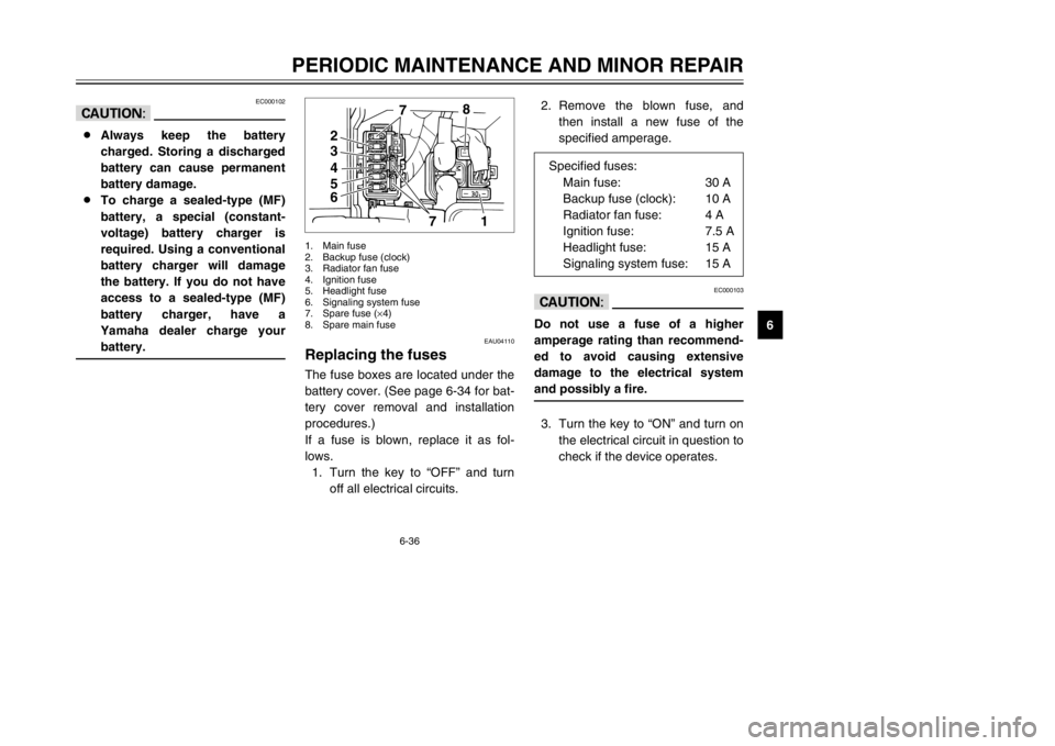
Replacing the fusesFuses, replacingThe fuse boxes are located under the
battery cover. (See page 6-34 for bat-
tery cover removal and installation
procedures.)
If a fuse is blown, replace it as fol-
lows.
1. Turn the key to “OFF” and turn
off all electrical circuits.
4
5
67
1
32
78
1. Main fuse
2. Backup fuse (clock)
3. Radiator fan fuse
4. Ignition fuse
5. Headlight fuse
6. Signaling system fuse
7. Spare fuse (×4)
8. Spare main fuse
EC000102
cC8Always keep the battery
charged. Storing a discharged
battery can cause permanent
battery damage.
8To charge a sealed-type (MF)
battery, a special (constant-
voltage) battery charger is
required. Using a conventional
battery charger will damage
the battery. If you do not have
access to a sealed-type (MF)
battery charger, have a
Yamaha dealer charge your
battery.
2. Remove the blown fuse, and
then install a new fuse of the
specified amperage.
EC000103
cCDo not use a fuse of a higher
amperage rating than recommend-
ed to avoid causing extensive
damage to the electrical system
and possibly a fire.3. Turn the key to “ON” and turn on
the electrical circuit in question to
check if the device operates. Specified fuses:
Main fuse: 30 A
Backup fuse (clock): 10 A
Radiator fan fuse: 4 A
Ignition fuse: 7.5 A
Headlight fuse: 15 A
Signaling system fuse: 15 A
5SJ-28199-E0 1/24/02 6:14 PM Page 85
Page 89 of 114
3. Remove the socket (together
with the turn signal light bulb) by
turning it counterclockwise.
4. Remove the defective bulb by
pushing it in and turning it coun-
terclockwise.
5. Insert a new bulb into the socket,
push it in, and then turn it clock-
wise until it stops.
6. Install the socket (together with
the bulb) by turning it clockwise.
7. Install the panel.
1
1. Socket
6-39
PERIODIC MAINTENANCE AND MINOR REPAIR
6
EAU03111
Replacing a front turn signal
light bulbTurn signal light bulb (front), replacing1. Place the scooter on the center-
stand.
2. Remove panel A. (See page
6-11 for panel removal and
installation procedures.) 7. Install the panel.
8. Have a Yamaha dealer adjust
the headlight beam if necessary.
5SJ-28199-E0 1/24/02 6:14 PM Page 88