Page 1082 of 1690

17±3
AVENSIS REPAIR MANUAL (RM1018E)
OIL PUMP ASSY(1ZZ±FE/3ZZ±FE)
REPLACEMENT
1.DRAIN ENGINE OIL
(a)Remove the oil pan drain")
170FR±01
B08737
A30890
±
LUBRICATION OIL PUMP ASSY(1ZZ±FE/3ZZ±FE)
17±3
AVENSIS REPAIR MANUAL (RM1018E)
OIL PUMP ASSY(1ZZ±FE/3ZZ±FE)
REPLACEMENT
1.DRAIN ENGINE OIL
(a)Remove the oil pan drain plug and drain engine oil.
2.REMOVAL & INSTALLATION CHAIN SUB±ASSY (See page 14±49)
3.REMOVE CHAIN VIBRATION DAMPER NO.1
(a)Remove the 2 bolts and the chain vibration damper No. 1.
4.REMOVE OIL PUMP ASSY
(a)Remove the 5 bolts.
(b)Remove the oil pump assy and the gasket.
5.INSTALL OIL PUMP ASSY
(a)Place a new gasket on the cylinder block.
(b)Align the keyway of the oil pump drive rotor with the rect-angular portion of the crankshaft and slide the oil pump
into place.
(c)Install the oil pump with the 5 bolts. Torque: 9.0 N �m (92 kgf �cm, 80 in. �lbf)
6.INSTALL CHAIN VIBRATION DAMPER NO.1
(a)Install the chain vibration damper No. 1 with 2 bolts. Torque: 9.0 N �m (92 kgf �cm,8.0 in. �lbf)
7.INSTALL OIL PAN DRAIN PLUG
(a)Clean and install the oil pan drain plug with a new gasket.
Torque: 37 N �m (377 kgf �cm,27 ft �lbf)
8.ADD ENGINE OIL (See page 17±4)
9.ADD ENGINE COOLANT (See page 16±7)
10. CHECK FOR ENGINE OIL LEAKS
11.CHECK FOR ENGINE COOLANT LEAKS (See page 16±1)
Page 1112 of 1690

41±1
AVENSIS REPAIR MANUAL (RM1018E)
MANUAL TRANSAXLE SYSTEM (MTM)
PROBLEM SYMPTOMS TABLE
Use the table below to help find t")
4100Y±05
±
MANUAL TRANSMISSION/TRANSAXLE MANUAL TRANSAXLE SYSTEM (MTM)
41±1
AVENSIS REPAIR MANUAL (RM1018E)
MANUAL TRANSAXLE SYSTEM (MTM)
PROBLEM SYMPTOMS TABLE
Use the table below to help find the cause of the problem. The numbers indi\
cate the likelihood of the possible
cause in descending order. Check each part in the order shown. Replace these parts as necessary.
�: (C50 MANUAL TRANSAXLE Repair Manual Pub. No. 826E or C250 MANUAL TRANS\
AXLE Repair
Manual Pub. No. RM1020E or E354 MANUAL TRANSAXLE Repair Manual Pub. No. RM944E\
)
SymptomSuspect AreaSee page
Noise
6. Oil (Level low)
7. Oil (Wrong) C50/C250
E354/E357
8. Gear (Worn or damaged)
9. Bearing (Worn or damaged)41±2
41±3
41±5 �
�
Oil leakage
1. Oil (Level too high)
2. Gasket (Damaged)
3. Oil seal (Worn or damaged) C50/ C250 E354/E357
4. O±Ring (Worn or damaged)41±2
�
41±3
41±5 �
Hard to shift or will not shift
1. Control cable (Faulty)
2. Synchronizer ring (Worn or damaged)
3. Shift key spring (Damaged)41±7
�
�
Jumps out of gear
1. Locking ball spring (Damaged)
2. Shift fork (Worn)
3. Gear (Worn or damaged)
4. Bearing (Worn or damaged)�
�
�
�
Page 1192 of 1690

(09083±00150)Test Lead SetAIR CONDITIONING SYSTEM
ABS WITH EBD SYSTEM
ELECTRONIC MOTOR POWER
STEERING SYSTEM
MULTIPLEX COMMUNICATION")
02±2
± PREPARATIONDIAGNOSTICS
AVENSIS REPAIR MANUAL (RM1018E)
(09083±00150)Test Lead SetAIR CONDITIONING SYSTEM
ABS WITH EBD SYSTEM
ELECTRONIC MOTOR POWER
STEERING SYSTEM
MULTIPLEX COMMUNICATION
SYSTEM
ENGINE IMMOBILISER SYSTEM
ABS WITH EBD & BA & TRC & VSC
SYSTEM
WIRELESS DOOR LOCK CONTROL
SYSTEM
COMBINATION METER
KEY REMINDER WARNING SYSTEM
POWER DOOR LOCK CONTROL
SYSTEM
SFI SYSTEM(1AZ±FE)
SFI SYSTEM(1AZ±FSE)
ECD SYSTEM(1CD±FTV)
SFI SYSTEM(1ZZ±FE/3ZZ±FE)
ELECTRONIC CONTROLLED
AUTOMATIC TRANSAXLE
[ECT](U241E(1AZ±FE))
ELECTRONIC CONTROLLED
AUTOMATIC TRANSAXLE
[ECT](U241E(1AZ±FSE))
ELECTRONIC CONTROLLED
AUTOMATIC TRANSAXLE
[ECT](U341E)
09082±00050TOYOTA Electrical Tester SetPOWER DOOR LOCK CONTROL
SYSTEM
(09083±00150)Test Lead SetAIR CONDITIONING SYSTEM
ABS WITH EBD SYSTEM
ELECTRONIC MOTOR POWER
STEERING SYSTEM
MULTIPLEX COMMUNICATION
SYSTEM
ENGINE IMMOBILISER SYSTEM
ABS WITH EBD & BA & TRC & VSC
SYSTEM
WIRELESS DOOR LOCK CONTROL
SYSTEM
COMBINATION METER
KEY REMINDER WARNING SYSTEM
POWER DOOR LOCK CONTROL
SYSTEM
SFI SYSTEM(1AZ±FE)
SFI SYSTEM(1AZ±FSE)
ECD SYSTEM(1CD±FTV)
SFI SYSTEM(1ZZ±FE/3ZZ±FE)
ELECTRONIC CONTROLLED
AUTOMATIC TRANSAXLE
[ECT](U241E(1AZ±FE))
ELECTRONIC CONTROLLED
AUTOMATIC TRANSAXLE
[ECT](U241E(1AZ±FSE))
ELECTRONIC CONTROLLED
AUTOMATIC TRANSAXLE
[ECT](U341E)
Page 1465 of 1690
F44782
Transponder Key Amplifier� Tapered±Head Bolt
Steering Column Clamp Upper
Ignition or Starter Switch Assy
Un±lock Warning
Switch Assy
Steering Column Upper W/Switch Bracket Assy Ignition Switch Lock Cylinder Assy
Non±reusable part �
Steering Column Assy
50±6
± STEERING COLUMNSTEERING COLUMN ASSY
AVENSIS REPAIR MANUAL (RM1018E)
Page 1467 of 1690
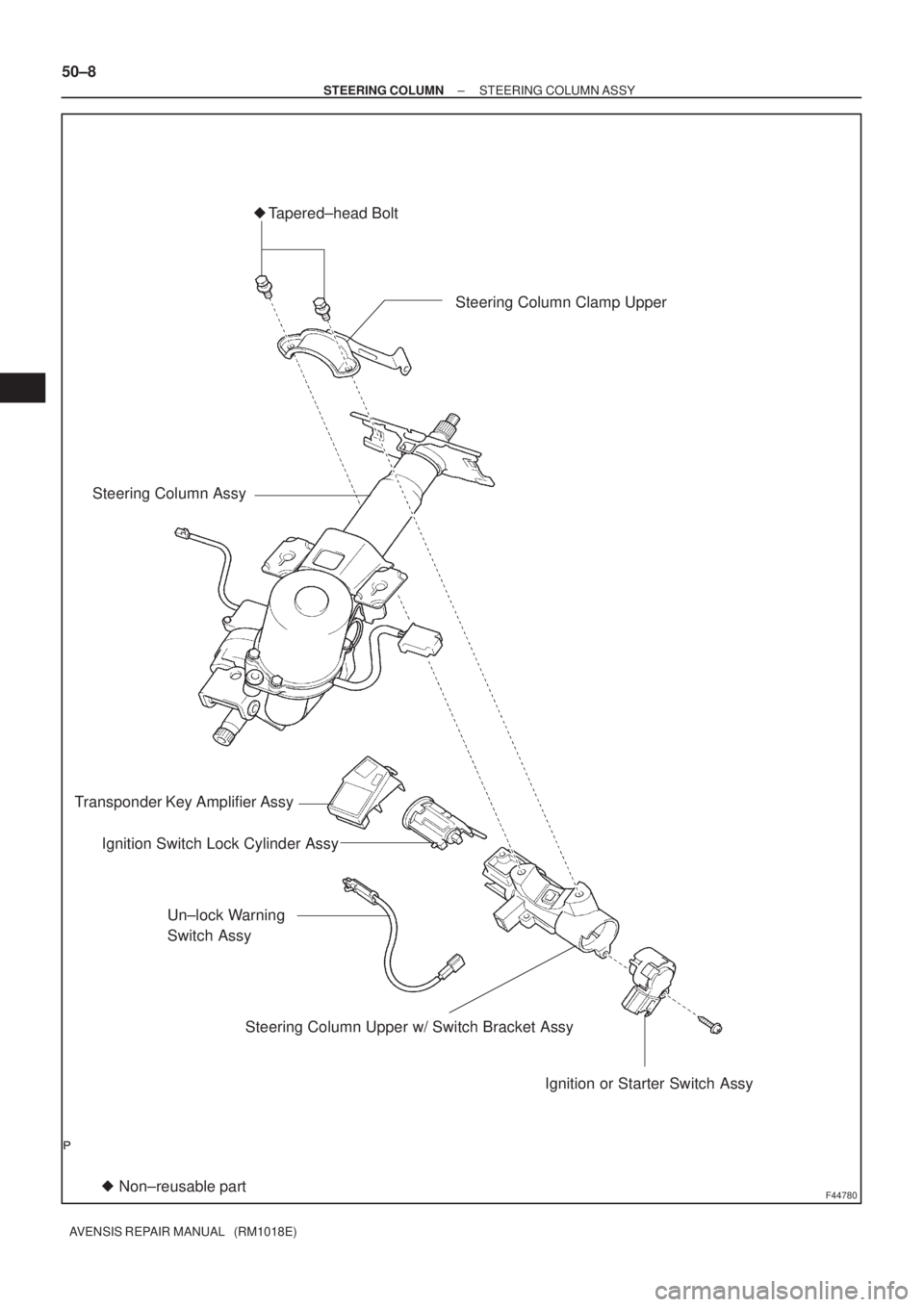
F44780
Transponder Key Amplifier AssyTapered±head Bolt
Ignition or Starter Switch Assy Steering Column Assy�
Non±reusable part �Steering Column Clamp Upper
Un±lock Warning
Switch Assy
Steering Column Upper w/ Switch Bracket Assy Ignition Switch Lock Cylinder Assy
50±8
± STEERING COLUMNSTEERING COLUMN ASSY
AVENSIS REPAIR MANUAL (RM1018E)
Page 1473 of 1690

33. REMOVE STEERING INTERMEDIATE SHAFT ASSY NO.2 (LHD")
F44793Matchmarks
F44794
Screw
Extractor
F44795
SST
F44796
F44797
50±14
±
STEERING COLUMN STEERING COLUMN ASSY
AVENSIS REPAIR MANUAL (RM1018E)
33. REMOVE STEERING INTERMEDIATE SHAFT ASSY NO.2 (LHD STEERING POSITION TYPE)
(a) Place matchmarks on the steering intermediate shaft
assy No. 2 and steering main shaft.
(b) Remove the bolt and steering intermediate shaft assy No. 2.
(c) W/VSC:
Remove the steering sensor (See page 32±65).
34. REMOVE STEERING COLUMN UPPER W/SWITCH BRACKET ASSY
(a) Using a centering punch, mark the center of the 2 ta- pered±head bolts.
(b) Using a 3 ± 4 mm (0.12 ± 0.16 in.)drill, drill into the 2 bolts.
(c) Using a screw extractor, remove the 2 bolts and steering column upper with switch bracket assy.
NOTICE:
Do not give the strong force to the motor part.
35. INSPECT STEERING COLUMN ASSY (ELECTRIC POWER STEERING)
(a) Using SST and a torque wrench, check the rotating torque.
SST 09616±00011
Rotating torque (1 turn for 2 sec.):
0.4 ± 1.1 N �m (4 ± 11 kgf �cm, 3.5 ± 9.5 in. �lbf)
36. REMOVE TRANSPONDER KEY AMPLIFIER
(a) Widen the claw hung on the upper bracket by approx. 1.0 mm (0.039 in.) using a screwdriver.
(b) Pull the transponder key amplifier toward the rear of the
vehicle with the claw open.
NOTICE:
Take care not to use excessive force to prevent the case
from being damaged.
37. REMOVE IGNITION SWITCH LOCK CYLINDER ASSY
(a) Place the ignition switch lock cylinder assy at the ACC position.
(b) Push down the stop pin with a screwdriver, and pull out the cylinder assy.
Page 1474 of 1690

38. REMOVE UN±LOCK WARNING SWITCH ASSY
(a) Slide the unlock warning switch assy out of")
F44798
F44799
F44793Matchmarks
±
STEERING COLUMN STEERING COLUMN ASSY
50±15
AVENSIS REPAIR MANUAL (RM1018E)
38. REMOVE UN±LOCK WARNING SWITCH ASSY
(a) Slide the unlock warning switch assy out of the steering column upper br\
acket.
39. REMOVE IGNITION OR STARTER SWITCH ASSY
(a) Remove the 2 screws and ignition or starter switch assy.
40. INSTALL IGNITION OR STARTER SWITCH ASSY
(a) Install the ignition or starter switch assy to the steering column upper w/swit\
ch bracket assy with the
2 screws.
41. INSTALL UN±LOCK WARNING SWITCH ASSY
(a) Install the un±lock warning switch assy.
(b) Connect the un±lock warning switch assy connector to the ignition or \
starter switch assy.
42. INSTALL IGNITION SWITCH LOCK CYLINDER ASSY
(a) Make sure of the ignition switch lock cylinder assy at the ACC position.\
(b) Install the ignition switch lock cylinder assy.
43. INSPECT STEERING LOCK OPERATION
(a) Check that the steering lock mechanism is activated when removing the ke\
y.
(b) Check that the steering lock mechanism is deactivated when inserting the\
key and turning it to ACC position.
44. INSTALL TRANSPONDER KEY AMPLIFIER
(a) Align the transponder key amplifier with the installationposition of the upper bracket with the amplifier inclined.
(b) Push the transponder key amplifier up and connect it to the upper bracket.
NOTICE:
Take care not to push the amplifier up with excessive force
to prevent it from being damaged.
45. INSTALL STEERING COLUMN UPPER W/SWITCH BRACKET ASSY
(a) Temporarily install the steering column upper with switch bracket assy and steering column upper clamp with 2 new
tapered±head bolts.
(b) Tighten the 2 tapared±head bolts until the bolt heads break off.
46. INSTALL STEERING SLIDING YOKE SUB±ASSY (RHD STEERING POSITION TYPE)
(a) W/VSC:
Install the steering sensor (See page 32±65).
(b) Align matchmarks on the steering sliding yoke and steer- ing main shaft.
(c) Oil Pressure Power Steering
(1) Install the steering sliding yoke with the bolt.
Torque: 28 N �m (286 kgf �cm, 21 ft �lbf)
Page 1557 of 1690
730GU±01
73±26
± THEFT DETERRENT & DOOR LOCKKEY REMINDER WARNING SYSTEM
AVENSIS REPAIR MANUAL (RM1018E)
KEY REMINDER WARNING SYSTEM
ON±VEHICLE INSPECTION
1. FUNCTION CHECK
(a) Check that the key reminder warning buzzer sounds.
(1) With the driver side door closed, insert the key into the ignition switch lock cylinder, and then turn
the key to LOCK.
(2) Then, check that the buzzer sounds intermittently when the driver side door is opened.
(b) Check that the key reminder warning buzzer stops.
(1) Check that the buzzer stops sounding when any of the following operations is done while the
buzzer is sounding.
�Close the driver side door (front door courtesy lamp switch assy is off).
�Turn the ignition switch ON.
�Pull out the key from the ignition switch lock cylinder.


KEY REMINDER WARNING SYSTEM
ON±VEHICLE INSPECTION
1. FUNCTION CHECK
(a) Check that the key")