Page 125 of 1690
D30057
1CD±FTV Engine Type:
Flywheel Sub±assyClutch Disc Assy
Clutch Release Fork Sub±assy Clutch Cover Assy
Release Bearing
Hub Clip Clutch Release
Bearing Assy
Release Fork Support
Clutch Release
Fork Boot
37 (375, 27)
19 (194, 14)
x6
Release hub grease
N�m (kgf�cm, ft�lbf) : Specified torque
�Non±reusable part
Clutch spline grease
± CLUTCHCLUTCH UNIT (MTM)
42±25
AVENSIS REPAIR MANUAL (RM1018E)
Page 126 of 1690
4200G±05
D26951
EXCEPT 1CD±FTV Engine Type:1CD±FTV Engine Type:
������D25280Matchmarks
42±26
±
CLUTCH CLUTCH UNIT (MTM)
AVENSIS REPAIR MANUAL (RM1018E)
OVERHAUL
1. REMOVE MANUAL TRANSAXLE ASSY
(a)1ZZ±FE, 3ZZ±FE Engine (See page 41±15)
(b)1AZ±FE, 1AZ±FSE Engine (See page 41±24)
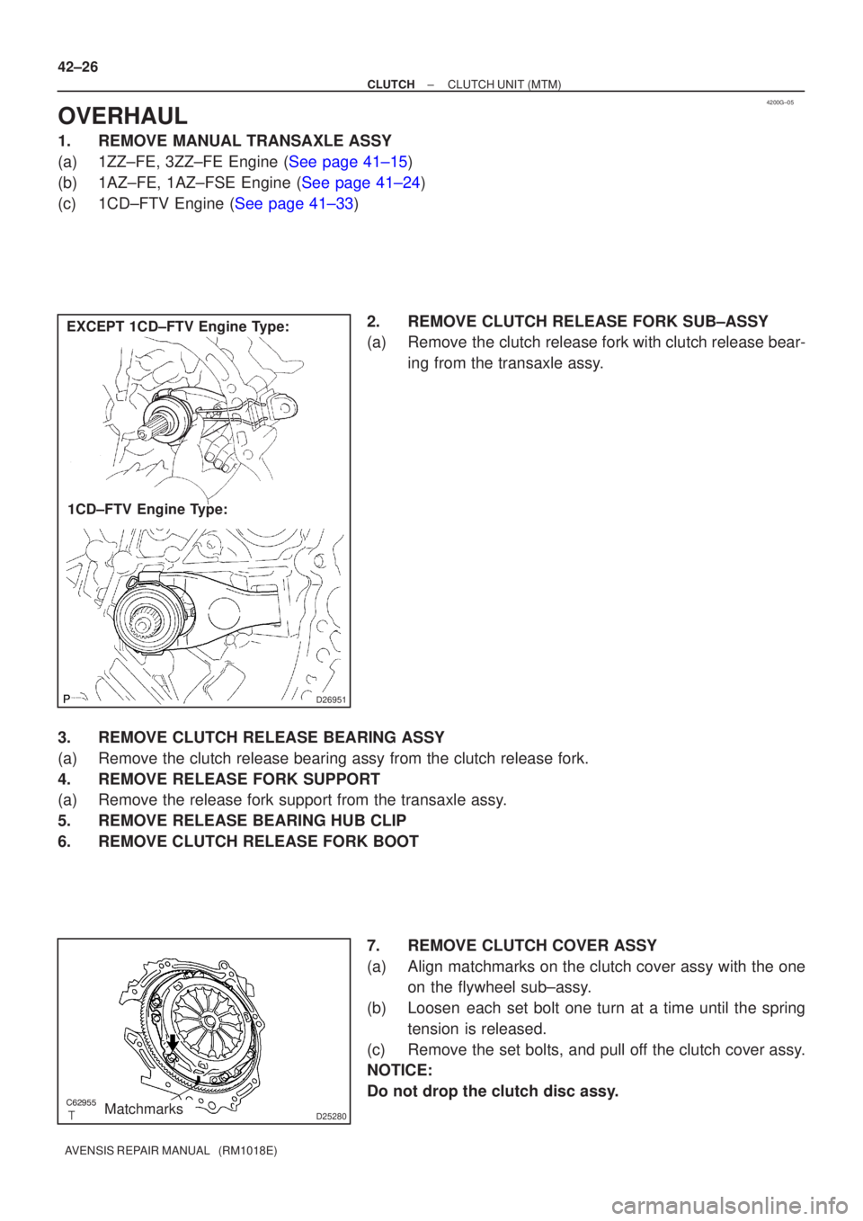
(c)1CD±FTV Engine (See page 41±33) 2. REMOVE CLUTCH RELEASE FORK SUB±ASSY
(a) Remove the clutch release fork with clutch release bear-ing from the transaxle assy.
3. REMOVE CLUTCH RELEASE BEARING ASSY
(a) Remove the clutch release bearing assy from the clutch release fork.
4. REMOVE RELEASE FORK SUPPORT
(a) Remove the release fork support from the transaxle assy.
5. REMOVE RELEASE BEARING HUB CLIP
6. REMOVE CLUTCH RELEASE FORK BOOT 7. REMOVE CLUTCH COVER ASSY
(a) Align matchmarks on the clutch cover assy with the oneon the flywheel sub±assy.
(b) Loosen each set bolt one turn at a time until the spring tension is released.
(c) Remove the set bolts, and pull off the clutch cover assy.
NOTICE:
Do not drop the clutch disc assy.
Page 127 of 1690
C62956
D30058
1CD±FTV Engine Type: Others:
Transaxle Side
������
D25281
AB
C62958
± CLUTCHCLUTCH UNIT (MTM)
42±27
AVENSIS REPAIR MANUAL (RM1018E)
8. REMOVE CLUTCH DISC ASSY
NOTICE:
Keep the lining part of the clutch disc assy, the pressure plate and surface of the flywheel sub±assy
away from oil and foreign attachment.
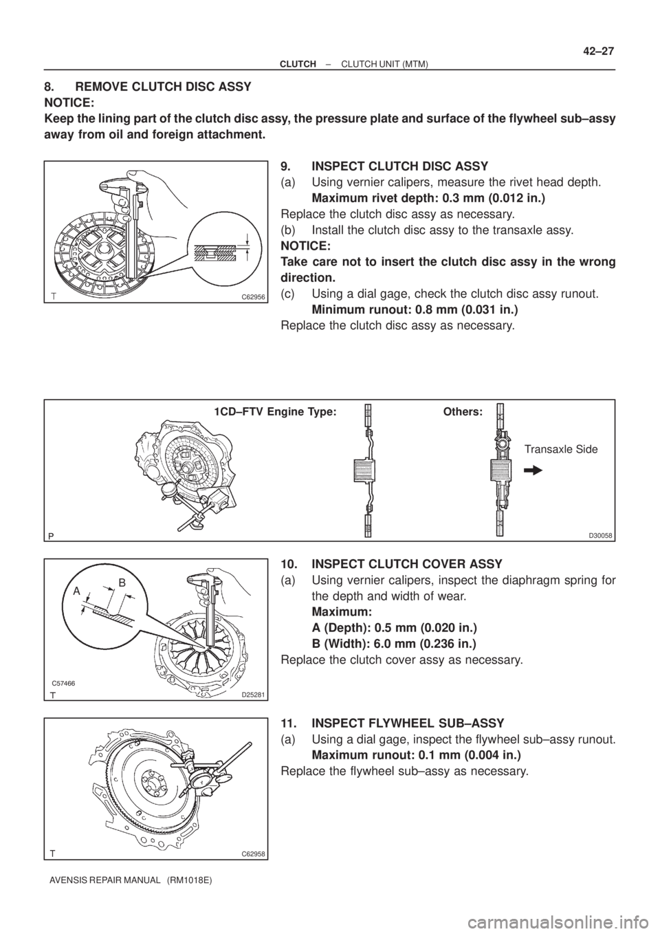
9. INSPECT CLUTCH DISC ASSY
(a) Using vernier calipers, measure the rivet head depth.
Maximum rivet depth: 0.3 mm (0.012 in.)
Replace the clutch disc assy as necessary.
(b) Install the clutch disc assy to the transaxle assy.
NOTICE:
Take care not to insert the clutch disc assy in the wrong
direction.
(c) Using a dial gage, check the clutch disc assy runout.
Minimum runout: 0.8 mm (0.031 in.)
Replace the clutch disc assy as necessary.
10. INSPECT CLUTCH COVER ASSY
(a) Using vernier calipers, inspect the diaphragm spring for
the depth and width of wear.
Maximum:
A (Depth): 0.5 mm (0.020 in.)
B (Width): 6.0 mm (0.236 in.)
Replace the clutch cover assy as necessary.
11. INSPECT FLYWHEEL SUB±ASSY
(a) Using a dial gage, inspect the flywheel sub±assy runout.
Maximum runout: 0.1 mm (0.004 in.)
Replace the flywheel sub±assy as necessary.
Page 128 of 1690
Q01060
D30059
1CD±FTV Engine Type: Others:
Flywheel Side
SST(s)
D26323
SST(s)
Matchmarks 7
1 (Temporally), 4
3
6
2.58
D00205
SST(s)
42±28
± CLUTCHCLUTCH UNIT (MTM)
AVENSIS REPAIR MANUAL (RM1018E)
12. INSPECT CLUTCH RELEASE BEARING ASSY
(a) Turn the release bearing by hand while applying force in
the axial direction.
HINT:
The bearing is permanently lubricated and requires no cleaning
or lubrication.
Replace the release bearing assy as necessary.
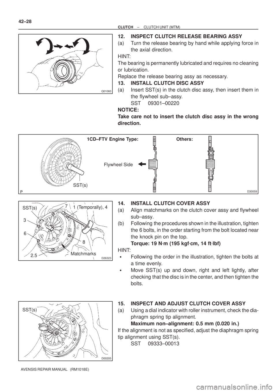
13. INSTALL CLUTCH DISC ASSY
(a) Insert SST(s) in the clutch disc assy, then insert them in
the flywheel sub±assy.
SST 09301±00220
NOTICE:
Take care not to insert the clutch disc assy in the wrong
direction.
14. INSTALL CLUTCH COVER ASSY
(a) Align matchmarks on the clutch cover assy and flywheel
sub±assy.
(b) Following the procedures shown in the illustration, tighten
the 6 bolts, in the order starting from the bolt located near
the knock pin on the top.
Torque: 19 N�m (195 kgf�cm, 14 ft�lbf)
HINT:
�Following the order in the illustration, tighten the bolts at
a time evenly.
�Move SST(s) up and down, right and left lightly, after
checking that the disc is in the center, and then tighten the
bolts.
15. INSPECT AND ADJUST CLUTCH COVER ASSY
(a) Using a dial indicator with roller instrument, check the dia-
phragm spring tip alignment.
Maximum non±alignment: 0.5 mm (0.020 in.)
If the alignment is not as specified, adjust the diaphragm spring
tip alignment using SST(s).
SST 09333±00013
Page 183 of 1690
160ME±01
A79148
SST
16±46
±
COOLING WATER PUMP ASSY(1CD±FTV)
AVENSIS REPAIR MANUAL (RM1018E)
WATER PUMP ASSY(1CD±FTV)
REPLACEMENT
1.REMOVE RADIATOR SUPPORT OPENING COVER
2.REMOVE ENGINE ROOM COVER SIDE
3.DRAIN ENGINE COOLANT(See page 16±44)
4.REMOVE FRONT WHEEL RH
5.REMOVE ENGINE UNDER COVER SUB±ASSY NO.1
6.REMOVE ENGINE UNDER COVER RH
7.REMOVE ENGINE COVER NO.1
(a)Remove the 5 nuts and the engine cover.
8.REMOVE INJECTOR DRIVER (See page 14±286)
9.REMOVE V (COOLER COMPRESSOR TO CRANKSHAFT PULLEY) BELT NO.1 (See page 14±269)
10.REMOVE GENERATOR V BELT (See page 14±269)
11.SEPARATE POWER STEERING IDLE PULLEY BRACKET (See page 14±286)
12.SEPARATE ENGINE MOUNTING INSULATOR SUB±ASSY RH(See page 14±307)
13.REMOVE CRANKSHAFT PULLEY(See page 14±307) SST 09213±54015 (90105±08076), 09330±00021, 09950±50013 (0995\
1±05010, 09952±05010, 09953±05020, 09954±05031)
14. REMOVE IDLER PULLEY SUB±ASSY
(a) Remove the bolt, the washer and the pulley.
15.REMOVE TIMING BELT NO.2 COVER(See page 14±307)
16.REMOVE TIMING BELT NO.1 COVER(See page 14±307)
17. REMOVE TIMING BELT GUIDE
18.REMOVE TRANSVERSE ENGINE ENGINE MOUNTING BRACKET(See page 14±307)
19.SET NO. 1 CYLINDER TO TDC/COMPRESSION(See page 14±307)
20.REMOVE TIMING CHAIN COVER PLATE(See page 14±307)
21.REMOVE TIMING BELT(See page 14±307)
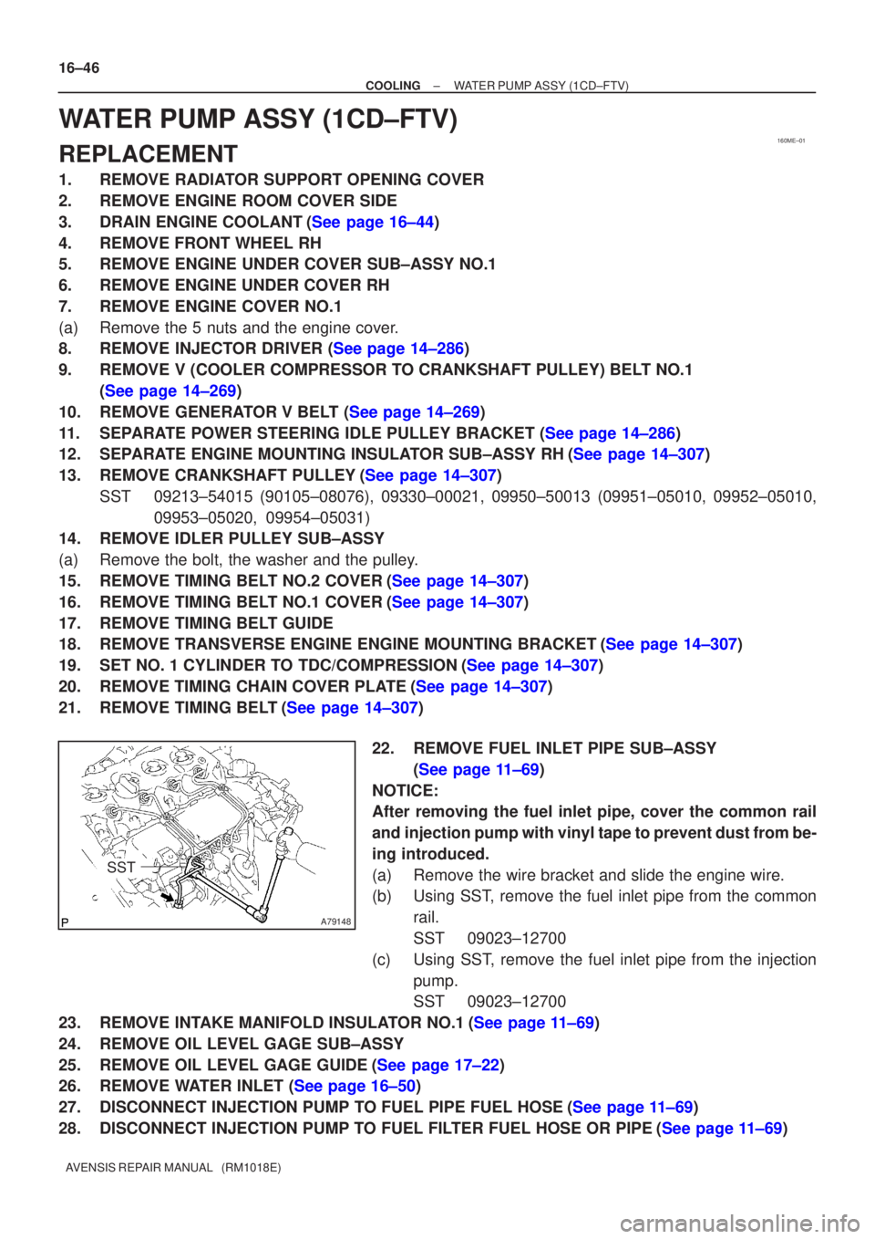
22. REMOVE FUEL INLET PIPE SUB±ASSY(See page 11±69)
NOTICE:
After removing the fuel inlet pipe, cover the common rail
and injection pump with vinyl tape to prevent dust from be-
ing introduced.
(a) Remove the wire bracket and slide the engine wire.
(b) Using SST, remove the fuel inlet pipe from the common rail.
SST 09023±12700
(c) Using SST, remove the fuel inlet pipe from the injection pump.
SST 09023±12700
23.REMOVE INTAKE MANIFOLD INSULATOR NO.1(See page 11±69)
24. REMOVE OIL LEVEL GAGE SUB±ASSY
25.REMOVE OIL LEVEL GAGE GUIDE(See page 17±22)
26.REMOVE WATER INLET (See page 16±50)
27.DISCONNECT INJECTION PUMP TO FUEL PIPE FUEL HOSE(See page 11±69)
28.DISCONNECT INJECTION PUMP TO FUEL FILTER FUEL HOSE OR PIPE(See page 11±69)
Page 186 of 1690
±
COOLING WATER PUMP ASSY(1CD±FTV)
16±49
AVENSIS REPAIR MANUAL (RM1018E)
41.SET NO. 1 CYLINDER TO TDC/COMPRESSION
SST09960±10010 (09962±01000, 09963±01000)
42.INSTALL TIMING BELT(See page 14±307)
43.CHECK VALVE TIMING(See page 14±307)
44.INSTALL TIMING CHAIN COVER PLATE(See page 14±307)
45.INSTALL TRANSVERSE ENGINE ENGINE MOUNTING BRACKET(See page 14±307)
46.INSTALL TIMING BELT GUIDE(See page 14±307)
47.INSTALL TIMING BELT NO.1 COVER(See page 14±307)
48.INSTALL TIMING BELT NO.2 COVER(See page 14±307)
49.INSTALL IDLER PULLEY SUB±ASSY(See page 11±69)
50.INSTALL CRANKSHAFT PULLEY(See page 14±307) SST 09213±54015 (90105±08076), 09330±00021
51.INSTALL ENGINE MOUNTING INSULATOR SUB±ASSY RH(See page 14±307)
52.INSTALL POWER STEERING IDLE PULLEY BRACKET (See page 14±286)
53.ADJUST V (COOLER COMPRESSOR TO CRANKSHAFT PULLEY) BELT NO.1 (See page 14±269)
54.INSTALL INJECTOR DRIVER(See page 11±69)
55. INSTALL FRONT WHEEL RH Torque: 103 N �m (1,050 kgf �cm, 76 ft �lbf)
56. INSTALL ENGINE COVER NO.1
Torque: 8.0 N �m (82 kgf �cm, 71 in. �lbf)
57.ADD ENGINE COOLANT(See page 16±44)
58.CHECK FOR ENGINE COOLANT LEAKS(See page 16±44)
59.CHECK FOR FUEL LEAKS(See page 11±60)
Page 188 of 1690
3005C±02
±
DRIVE SHAFT / PROPELLER SHAFT DRIVE SHAFT, PROPELLER SHAFT, AXLE
30±1
AVENSIS REPAIR MANUAL (RM1018E)
DRIVE SHAFT, PROPELLER SHAFT, AXLE
PROBLEM SYMPTOMS TABLE
Use the table below to help you find the cause of the problem. The numbers \
indicate the priority of
the likely cause of the problem. Check each part in order. If necessary, replace these parts.
SymptomSuspect AreaSee page
Wander
5. Wheel
6. Front wheel alignment
7. Rear wheel alignment
8. Hub bearing (Worn)
9. Front shock absorber
10.Rear shock absorber28±1
26±6
27±4
30±2
26±10
27±8
Front wheel shimmy
1. Wheel (Imbalance)
2. Hub bearing (Worn)
3. Lower suspension arm ATM:
4. Lower suspension arm MTM:
5. Lower ball joint (Worm)
6. Front shock absorber28±1
30±2
26±16
26±21
26±24
26±10
Noise (Front)
1. Front drive shaft
2. Front shock absorber
3. Hub bearing (Worn)
4. Lower ball joint (Worm)30±6
26±10 30±2
26±24
Noise (Rear)1. Hub bearing (Worn)
2. Rear shock absorber30±2
27±8
Page 191 of 1690
300JY±01
������F45751
SST
C80291
F44775
C67088
30±22
±
DRIVE SHAFT / PROPELLER SHAFT FRONT AXLE HUB SUB±ASSY LH
AVENSIS REPAIR MANUAL (RM1018E)
REPLACEMENT
HINT:
Replace the RH side by the same procedures as the LH side.
1. REMOVE FRONT WHEEL
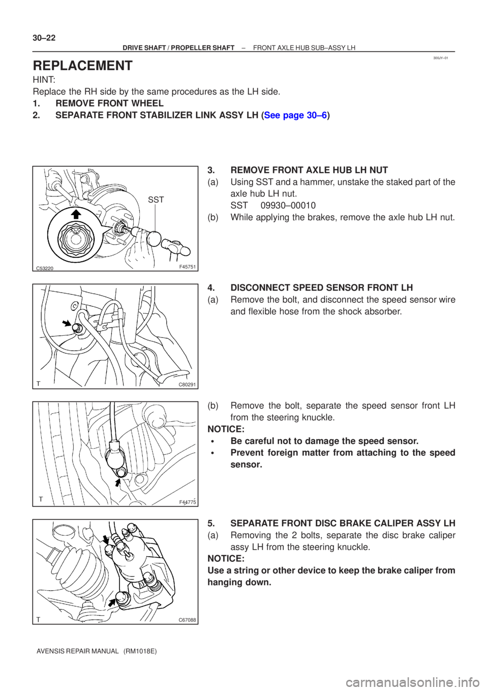
2.SEPARATE FRONT STABILIZER LINK ASSY LH (See page 30±6) 3. REMOVE FRONT AXLE HUB LH NUT
(a) Using SST and a hammer, unstake the staked part of theaxle hub LH nut.
SST 09930±00010
(b) While applying the brakes, remove the axle hub LH nut.
4. DISCONNECT SPEED SENSOR FRONT LH
(a) Remove the bolt, and disconnect the speed sensor wire and flexible hose from the shock absorber.
(b) Remove the bolt, separate the speed sensor front LH from the steering knuckle.
NOTICE:
�Be careful not to damage the speed sensor.
�Prevent foreign matter from attaching to the speed
sensor.
5. SEPARATE FRONT DISC BRAKE CALIPER ASSY LH
(a) Removing the 2 bolts, separate the disc brake caliper assy LH from the steering knuckle.
NOTICE:
Use a string or other device to keep the brake caliper from
hanging down.