Page 1574 of 1690

73±34
± THEFT DETERRENT & DOOR LOCKTHEFT DETERRENT SYSTEM
AVENSIS REPAIR MANUAL (RM1018E)
3. FORCED DOOR LOCK CONTROL
(a) The forced door lock control prevents the vehicle from being tampered with. Immediately after a door
is unlocked (alarm starts), the door is forced to lock by a forced door lock signal.
(1) Conditions that force the doors to lock:
When no key is in the ignition key cylinder and 0.4 seconds have elapsed after the previous out-
put of a forced door lock signal, the doors will be forced to lock if any of the following conditions
is present.
�The theft deterrent system is in the armed state of active arming mode.
�All the doors are locked.�Any door is unlocked.
�Any door is unlocked.
HINT:
Only Europe:
Forced door lock control does not operate if any door is unlocked by key.
4. ALARM MEMORY FUNCTION
(a) If the alarm is set off (tampering is detected) while the theft deterrent system is set, the alarm memory
function will record it. Whenever you cancel the theft deterrent system, the alarm memory function
causes the taillights to light up for 2 seconds in order to inform you that the alarm has been set off.
(1) Conditions of the alarm memory function that cause the taillights to light up:
When the theft deterrent system has entered into the alarm sounding state (tampering has been
detected) even once, the taillights will light up for 2 seconds if any of the following conditions is
present.
�Switched to the disarmed state from the armed state.
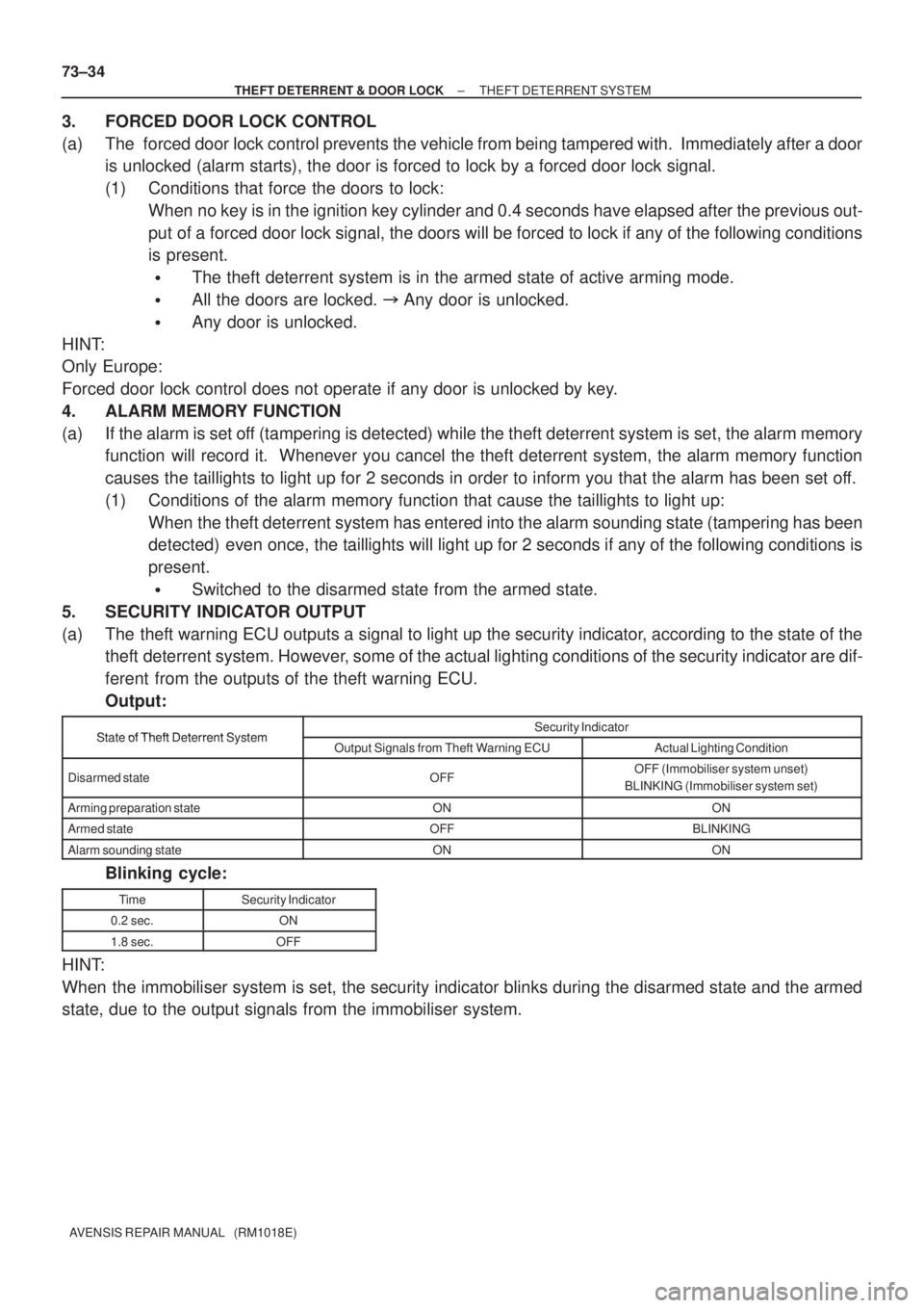
5. SECURITY INDICATOR OUTPUT
(a) The theft warning ECU outputs a signal to light up the security indicator, according to the state of the
theft deterrent system. However, some of the actual lighting conditions of the security indicator are dif-
ferent from the outputs of the theft warning ECU.
Output:
State of Theft Deterrent SystemSecurity IndicatorState of Theft Deterrent SystemOutput Signals from Theft Warning ECUActual Lighting Condition
Disarmed stateOFFOFF (Immobiliser system unset)
BLINKING (Immobiliser system set)
Arming preparation stateONON
Armed stateOFFBLINKING
Alarm sounding stateONON
Blinking cycle:
TimeSecurity Indicator
0.2 sec.ON
1.8 sec.OFF
HINT:
When the immobiliser system is set, the security indicator blinks during the disarmed state and the armed
state, due to the output signals from the immobiliser system.
Page 1578 of 1690

730EZ±03
I34799
±
THEFT DETERRENT & DOOR LOCK TRANSMITTER SUB±ASSY MODULE SET DOOR
CONTROL73±19
AVENSIS REPAIR MANUAL (RM1018E)
INSPECTION
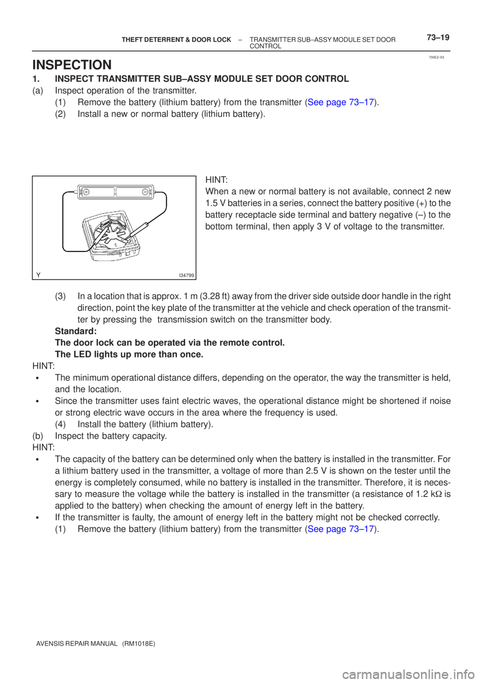
1.INSPECT TRANSMITTER SUB±ASSY MODULE SET DOOR CONTROL
(a)Inspect operation of the transmitter.
(1)Remove the battery (lithium battery) from the transmitter (See page 73±17).
(2)Install a new or normal battery (lithium battery).
HINT:
When a new or normal battery is not available, connect 2 new
1.5 V batteries in a series, connect the battery positive (+) to the
battery receptacle side terminal and battery negative (±) to the
bottom terminal, then apply 3 V of voltage to the transmitter.
(3)In a location that is approx. 1 m (3.28 ft) away from the driver side ou\
tside door handle in the right direction, point the key plate of the transmitter at the vehicle and che\
ck operation of the transmit-
ter by pressing the transmission switch on the transmitter body.
Standard:
The door lock can be operated via the remote control.
The LED lights up more than once.
HINT:
�The minimum operational distance differs, depending on the operator, the way the transmitter is held,
and the location.
�Since the transmitter uses faint electric waves, the operational distanc\
e might be shortened if noise
or strong electric wave occurs in the area where the frequency is used.
(4)Install the battery (lithium battery).
(b)Inspect the battery capacity.
HINT:
�The capacity of the battery can be determined only when the battery is inst\
alled in the transmitter. For
a lithium battery used in the transmitter, a voltage of more than 2.5 V is shown on the tester until the
energy is completely consumed, while no battery is installed in the transmitte\
r. Therefore, it is neces-
sary to measure the voltage while the battery is installed in the transmitte\
r (a resistance of 1.2 k �is
applied to the battery) when checking the amount of energy left in the \
battery.
�If the transmitter is faulty, the amount of energy left in the battery might not be checked correctl\
y.
(1)Remove the battery (lithium battery) from the transmitter (See page 73±17).
Page 1586 of 1690

730EV±02
±
THEFT DETERRENT & DOOR LOCK WIRELESS DOOR LOCK CONTROL SYSTEM
73±15
AVENSIS REPAIR MANUAL (RM1018E)
ON±VEHICLE INSPECTION
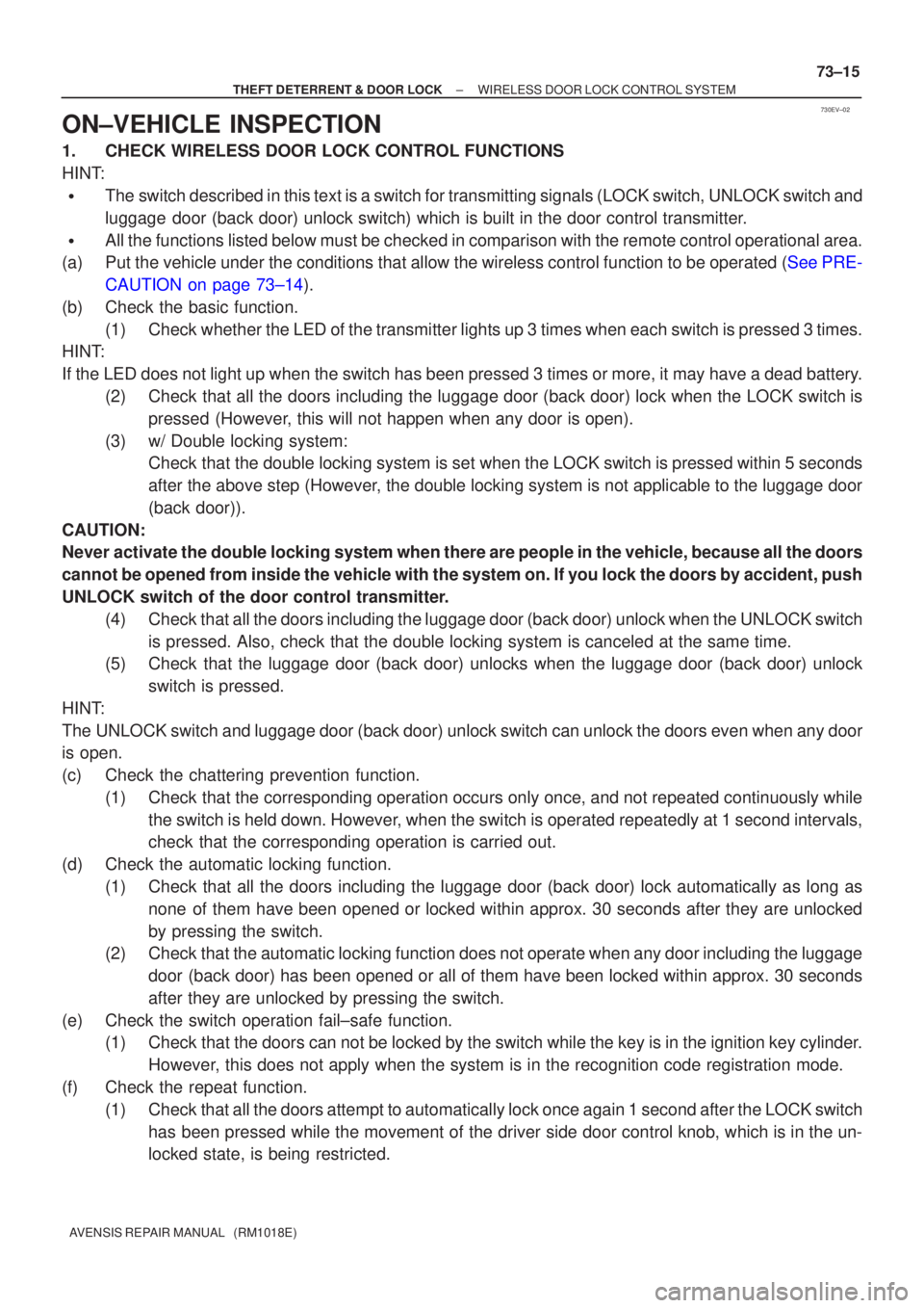
1.CHECK WIRELESS DOOR LOCK CONTROL FUNCTIONS
HINT:
�The switch described in this text is a switch for transmitting signals (LO\
CK switch, UNLOCK switch and
luggage door (back door) unlock switch) which is built in the door control t\
ransmitter.
�All the functions listed below must be checked in comparison with the re\
mote control operational area.
(a)Put the vehicle under the conditions that allow the wireless control fun\
ction to be operated (See PRE-
CAUTION on page 73±14).
(b) Check the basic function. (1) Check whether the LED of the transmitter lights up 3 times when each switch i\
s pressed 3 times.
HINT:
If the LED does not light up when the switch has been pressed 3 times or more, it may have a dead bat\
tery.
(2) Check that all the doors including the luggage door (back door) lock when t\
he LOCK switch ispressed (However, this will not happen when any door is open).
(3) w/ Double locking system: Check that the double locking system is set when the LOCK switch is pressed within 5 seconds
after the above step (However, the double locking system is not applicable to the luggage door
(back door)).
CAUTION:
Never activate the double locking system when there are people in the vehicle, because all the doors
cannot be opened from inside the vehicle with the system on. If you lock\
the doors by accident, push
UNLOCK switch of the door control transmitter. (4) Check that all the doors including the luggage door (back door) unlock when\
the UNLOCK switchis pressed. Also, check that the double locking system is canceled at th\
e same time.
(5) Check that the luggage door (back door) unlocks when the luggage door (bac\
k door) unlock
switch is pressed.
HINT:
The UNLOCK switch and luggage door (back door) unlock switch can unlock t\
he doors even when any door
is open.
(c) Check the chattering prevention function. (1) Check that the corresponding operation occurs only once, and not repeated continuously whilethe switch is held down. However, when the switch is operated repeatedly at 1 second intervals,
check that the corresponding operation is carried out.
(d) Check the automatic locking function. (1) Check that all the doors including the luggage door (back door) lock automatically as long asnone of them have been opened or locked within approx. 30 seconds after they\
are unlocked
by pressing the switch.
(2) Check that the automatic locking function does not operate when any door incl\
uding the luggage
door (back door) has been opened or all of them have been locked within ap\
prox. 30 seconds
after they are unlocked by pressing the switch.
(e) Check the switch operation fail±safe function. (1) Check that the doors can not be locked by the switch while the key is in the \
ignition key cylinder.
However, this does not apply when the system is in the recognition code registra\
tion mode.
(f) Check the repeat function. (1) Check that all the doors attempt to automatically lock once again 1 second af\
ter the LOCK switchhas been pressed while the movement of the driver side door control knob, which is in the un-
locked state, is being restricted.
Page:
< prev 1-8 9-16 17-24