Page 408 of 1690
A77285
Unleaded Gasoline
Timing
Marks
Leaded Gasoline
Timing
Marks
Timing
Marks
Timing
Marks
A52505
A77388
SST
± ENGINE MECHANICALCHAIN SUB±ASSY (1AZ±FE)
14±147
AVENSIS REPAIR MANUAL (RM1018E)
39. INSTALL CRANKSHAFT TIMING GEAR OR SPROCKET
40. SET NO. 1 CYLINDER TO TDC/COMPRESSION
(a) Turn the camshafts with a wrench on the hexagonal lobe,
and align the timing marks of the camshaft timing gear
with each timing mark located on the No. 1 and No. 2
bearing caps as shown in the illustration.
(b) Using the crankshaft pulley bolt, turn the crankshaft and
position the key on the crankshaft upward.
41. INSTALL CHAIN VIBRATION DAMPER NO.1
42. INSTALL CHAIN SUB±ASSY
Page 423 of 1690

14±343
AVENSIS REPAIR MANUAL (RM1018E)
20.REMOVE TIMING BELT(See page 14±")
SST
A09582
B07973
Cut PositionPry
SST
A08528
SST
A09583
Angle
SensorInward
±
ENGINE MECHANICAL CRANKSHAFT SEAL(1CD±FTV)
14±343
AVENSIS REPAIR MANUAL (RM1018E)
20.REMOVE TIMING BELT(See page 14±307)
21.REMOVE CRANKSHAFT TIMING PULLEY
(a)If the timing pulley cannot be removed by hand, use SSTto remove the pulley.
SST09950±50013 (09951±05010, 09952±05010, 09953±05010, 09953±05020, 09954±05021)
22.REMOVE CRANKSHAFT SEAL
(a)Using a knife, cut off the oil seal lip.
(b)Using a screwdriver, pry out the oil seal.
NOTICE:
Be careful not to damage the crankshaft. Warp tip of the
screwdriver with tape.
23.INSTALL CRANKSHAFT SEAL
(a)Using SST and a hammer, tap in the oil seal until its sur- face is flush with the oil pump edge.
SST09316±60011 (09316±00011)
24.INSTALL CRANKSHAFT TIMING PULLEY
(a)Align the keyway of the timing pulley with the key located on the crankshaft, slide the pulley into place.
(b)Using SST and a hammer, tap in the timing pulley with the angle sensor facing inward.
SST09223±46011
25.SET NO. 1 CYLINDER TO TDC/COMPRESSION(See page 14±307) SST 09960±10010 (09962±01000, 09963±01000)
26.INSTALL TIMING BELT(See page 14±307)
27.CHECK VALVE TIMING(See page 14±307)
28.INSTALL TIMING CHAIN COVER PLATE(See page 14±307)
Page 453 of 1690
A79431
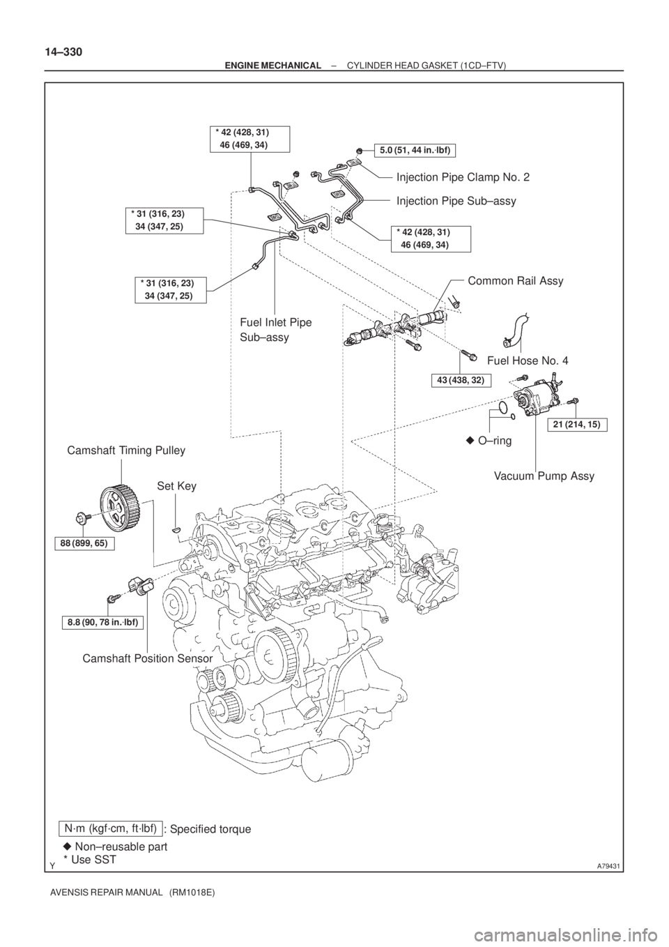
N´m (kgf´cm, ft´lbf)
: Specified torque
� Non±reusable part
* Use SST
5.0 (51, 44 in.�lbf)
* 31 (316, 23)
34 (347, 25)
* 31 (316, 23)
34 (347, 25)
Injection Pipe Clamp No. 2
Injection Pipe Sub±assy
* 42 (428, 31)
46 (469, 34)
Fuel Inlet Pipe
Sub±assy
� O±ring
43 (438, 32)
21 (214, 15)
Common Rail Assy
Fuel Hose No. 4
Camshaft Position Sensor
Set Key Camshaft Timing Pulley
88 (899, 65)
Vacuum Pump Assy
8.8 (90, 78 in.�lbf)
* 42 (428, 31)
46 (469, 34)
14±330
± ENGINE MECHANICALCYLINDER HEAD GASKET (1CD±FTV)
AVENSIS REPAIR MANUAL (RM1018E)
Page 478 of 1690

14±89
AVENSIS REPAIR MANUA")
A62170
Set KeyUpward
A62171
Yellow
Color Link
Timing Mark
A62172
SST
A62173
Yellow Color Mark
Timing Mark
A30867
± ENGINE MECHANICALCYLINDER HEAD GASKET (1ZZ±FE/3ZZ±FE)
14±89
AVENSIS REPAIR MANUAL (RM1018E)
(2) Using a crankshaft pulley bolt, turn the crankshaft
and set the set key on the crankshaft upward.
(b) Install the timing chain on the crankshaft timing sprocket
with the yellow color link and the timing mark on the crank-
shaft timing sprocket aligned.
HINT:
Three yellow color links are on the chain.
(c) Using SST, install the crankshaft timing sprocket.
SST 09223±22010
(d) Install the timing chain to the camshaft timing sprockets
with the yellow color links and the timing marks on the
camshaft timing sprockets aligned.
55. INSTALL CHAIN VIBRATION DAMPER NO.1
(a) Install chain vibration damper with the 2 bolts.
Torque: 9.0 N�m (92 kgf�cm, 80 in.�lbf)
56. INSTALL CHAIN TENSIONER SLIPPER
(a) Install the chain tensioner slipper with the bolt.
Torque: 19 N�m (194 kgf�cm, 14 ft�lbf)
57. INSTALL CRANKSHAFT POSITION SENSOR PLATE
NO.1
(a) Install the plate with the ºFº mark facing forward.
Page 481 of 1690

AVENSIS REPAIR MANUAL (RM1018E)
62.INSTALL TRANSVERSE")
A12816
A11858
A62837SST
A62180
DisconnectHook
PinTurn
A62181
Plunger
Turn
Push
14±92
±
ENGINE MECHANICAL CYLINDER HEAD GASKET(1ZZ±FE/3ZZ±FE)
AVENSIS REPAIR MANUAL (RM1018E)
62.INSTALL TRANSVERSE ENGINE ENGINE MOUNTING BRACKET
(a)Install the transverse engine engine mounting bracket
with the 3 bolts.
Torque: 47 N �m (479 kgf �cm, 35 ft �lbf)
63.INSTALL WATER PUMP ASSY (See page 16±9)
64. INSTALL V±RIBBED BELT TENSIONER ASSY
(a) Install the V±ribbed belt tensioner with the nut and bolt. Torque:
29 N�m (296 kgf �cm, 21 ft �lbf) for Nut
69 N �m (704 kgf �cm, 51 ft �lbf) for Bolt
65. INSTALL CRANKSHAFT PULLEY
(a) Align the keyway of the pulley with the key located on the crankshaft and slide the pulley into place.
(b) Using SST, install the crankshaft pulley bolt. SST 09960±10010 (09962±01000, 09963±01000)
Torque: 138 N �m (1,407 kgf �cm, 102 ft �lbf)
(c) Turn the crankshaft counterclockwise and take the hook off the knock pin to release the plunger.
(d) Turn the crankshaft clockwise, and check that the plunger is extended.
HINT:
If the plunger does not be extended, press the slipper into the
chain tensioner using a screwdriver so that the hook is took off
from the knock pin and let the plunger can be extended.
Page 557 of 1690

14±299
AVENSIS REPAIR MANUAL (RM1018E)
132.INSTALL VACUUM PUMP ASSY
(a)Install 2 new O±rings")
A79196
New O±Ring
New O±Ring
A79182
Collar
Groove
±
ENGINE MECHANICAL PARTIAL ENGINE ASSY(1CD±FTV)
14±299
AVENSIS REPAIR MANUAL (RM1018E)
132.INSTALL VACUUM PUMP ASSY
(a)Install 2 new O±rings to the vacuum pump.
(b)Align the key of the vacuum pump with the keyway of the
exhaust camshaft, insert the vacuum pump into place.
Secure the pump with the 2 bolts.
Torque: 21 N �m (214 kgf �cm, 15 ft �lbf)
133.INSTALL EGR VALVE ASSY
(a)Install a new gasket and the EGR valve with the bolt and 2 nuts. Torque: 18 N �m (184 kgf �cm, 13 ft �lbf)
134.INSTALL INTAKE AIR CONNECTOR SUB±ASSY
(a)Install a new gasket and the intake air connector with diesel throttle b\
ody with the bolt and 2 nuts. Torque: 21 N �m (214 kgf �cm, 15 ft �lbf)
135.INSTALL WATER OUTLET SUB±ASSY
(a)Install a new gasket and the water outlet with the 2 bolts. Torque: 21 N �m (214 kgf �cm,15 ft �lbf)
136.INSTALL OIL COOLER ASSY (See page 17±32)
137.INSTALL EXHAUST MANIFOLD
(a)Install a new gasket, the exhaust manifold and the 8 col-lars with new 8 nuts.
Torque: 47 N �m (479 kgf �cm, 35 ft �lbf)
HINT:
When installing the collars, pay attention to the mounting
orientation. Ring groove of the collar should be outside. Refer
to the illustration on the left.
138.INSTALL EGR PIPE SUB±ASSY NO.1
(a)Install 2 new gaskets and the EGR pipe with the bolt and 4 new nuts. Torque:
37 N�m (375 kgf �cm,27 ft �lbf) for bolt
25 N �m (250 kgf �cm,18 ft �lbf) for nut
139.INSTALL TURBOCHARGER SUB±ASSY (See page 13±11)
140.INSTALL TURBO OIL INLET PIPE SUB±ASSY (See page 13±11)
141.INSTALL TURBOCHARGER STAY (See page 13±11)
142.INSTALL EXHAUST MANIFOLD CONVERTER SUB±ASSY (See page 13±11)
143.INSTALL MANIFOLD STAY NO.2 (See page 13±11)
144.INSTALL EXHAUST MANIFOLD HEAT INSULATOR NO.2 (See page 13±11)
145.INSTALL TURBO INSULATOR NO.1 (See page 13±11)
146.INSTALL TURBO INSULATOR NO.2 (See page 13±11)
Page 596 of 1690

AVENSIS REPAIR MANUAL (RM1018E)
(b)Install the No. 1 timing belt cover and the gasket with the 5 bolt")
A09602
Seal
Packing
Gasket
Groove
A61186
SST
14±312
±
ENGINE MECHANICAL TIMING BELT(1CD±FTV)
AVENSIS REPAIR MANUAL (RM1018E)
(b)Install the No. 1 timing belt cover and the gasket with the 5 bolts and 5 seal washers.
Torque: 7.4 N �m (75 kgf �cm,65 in. �lbf)
(c)After installing the belt cover, check that there is no peel- ings of the gasket.
28.INSTALL TIMING BELT NO.2 COVER
(a)Check the timing belt cover gasket for cracks or deteriora- tions etc.
If the gasket has cracks or has deteriorated, replace it by the
following steps: (1)Using a screwdriver and gasket scraper, remove allthe old gasket.
(2)Thoroughly clean all components to remove all the loose material.
(3)Remove the backing paper from a new gasket and affix the gasket to the timing belt cover as shown in
the illustration.
NOTICE:
�Affix the gasket at the center of the groove.
�At the corners, try to keep the gasket thickness uni-
form.
(4)After installing the gasket, press it down so that the adhesive firmly sticks to the timing belt cover.
(5)If there is a gap where the end of the gasket meets,
use a seal packing to close the gap.
Seal packing: Part No. 08826±00080 or equivalent
(b)Install the No. 2 timing belt cover and the gasket with the 7 bolts and 7 seal washers.
Torque: 7.4 N �m (75 kgf �cm,65 in. �lbf)
29.INSTALL IDLER PULLEY SUB±ASSY Torque: 40 N �m (408 kgf �cm, 30 ft �lbf)
30.INSTALL CRANKSHAFT PULLEY
(a)Align the keyway of the pulley with the key located on the crankshaft, slide the pulley into place.
(b)Using SST, install the pulley bolt. SST09213±54015 (90105±08076), 09330±00021
Torque: 180 N´m (1,835 kgf´cm, 133 ft´lbf)
HINT:
When using a bolt (91651±60855), a plate washer (5 mm or
0.20 in.) must be inserted between the pulley bolt and SST.
31.INSTALL ENGINE MOUNTING INSULATOR SUB±ASSY RH Torque:52 N´m (530 kgf´cm, 38 ft´lbf)
32.INSTALL POWER STEERING IDLE PULLEY BRACKET (See page 14±286)
33. ADJUST V (COOLER COMPRESSOR TO CRANKSHAFT PULLEY) BELT NO.1 (See page 14±269)
Page 599 of 1690
14±97
AVENSIS REPAIR MANUAL (RM1018E)
9. REMOVE TIMING GEAR COVER OIL SE")
A62183
Cut Position
Pry
A62184
SST
A62837SST
A64005
± ENGINE MECHANICALTIMING CHAIN OR BELT COVER OIL
SEAL (1ZZ±FE/3ZZ±FE)14±97
AVENSIS REPAIR MANUAL (RM1018E)
9. REMOVE TIMING GEAR COVER OIL SEAL
(a) Using a knife, cut off the oil seal lip.
(b) Using a screwdriver with the tip wrapped in tape, pry out
the oil seal.
NOTICE:
After the removal, check if the crankshaft is not damaged.
If it is damaged, smooth the surface with 400±grit sandpa-
per.
10. INSTALL TIMING GEAR COVER OIL SEAL
(a) Apply MP grease to a new oil seal lip.
NOTICE:
Keep the lip free of foreign objects.
(b) Using SST, tap in the oil seal until its surface is flush with
the timing chain cover edge.
SST 09223±22010
NOTICE:
Wipe off extra grease on the crankshaft.
11. INSTALL CRANKSHAFT PULLEY
(a) Align the keyway of the pulley with the key located on the
crankshaft and slide the pulley into place.
(b) Using SST, install the crankshaft pulley bolt.
SST 09960±10010 (09962±01000, 09963±01000)
Torque: 138 N�m (1,407 kgf�cm, 102 ft�lbf)
12. INSTALL ENGINE MOUNTING INSULATOR
SUB±ASSY RH
(a) Install the engine mounting insulator with the 4 bolts and
2 nuts.
Torque: 52 N�m (530 kgf�cm, 38 ft�lbf)
13. INSTALL FRONT WHEEL RH
Torque: 103 N�m (1,050 kgf�cm, 76 ft�lbf)
14. CHECK FOR ENGINE OIL LEAKS

14±147
AVENSIS REPAIR MANUAL (RM1018")