Page 358 of 1690

AVENSIS REPAIR MANUAL (RM1018E)
REPLACEMENT
1.REMOVE FRONT WHEEL RH
2.REMOVE ENGINE UNDER COVER SUB±ASSY NO.1
3.ENGINE UNDER COVE")
141C8±01
SSTA61187
14±318
±
ENGINE MECHANICAL CAMSHAFT(1CD±FTV)
AVENSIS REPAIR MANUAL (RM1018E)
REPLACEMENT
1.REMOVE FRONT WHEEL RH
2.REMOVE ENGINE UNDER COVER SUB±ASSY NO.1
3.ENGINE UNDER COVER RH
4.REMOVE RADIATOR SUPPORT OPENING COVER
5.REMOVE ENGINE ROOM COVER SIDE
6.REMOVE ENGINE COVER NO.1
(a)Remove the 5 nuts and the engine cover.
7.REMOVE AIR CLEANER ASSY (See page 11±60)
8.REMOVE VACUUM RESERVOIR SUB±ASSY
(a)Disconnect the 2 vacuum hoses and the connector.
(b)Remove the 2 bolts and the vacuum reservoir.
9.REMOVE AIR TUBE NO.1 (See page 14±270)
10.REMOVE INJECTOR DRIVER (See page 14±286)
11. REMOVE V (COOLER COMPRESSOR TO CRANKSHAFT PULLEY) BELT NO.1 (See page 14±269)
12.REMOVE GENERATOR V BELT (See page 14±269)
13.SEPARATE POWER STEERING IDLE PULLEY BRACKET (See page 14±286)
14.REMOVE ENGINE MOUNTING INSULATOR SUB±ASSY RH (See page 14±307)
15.REMOVE CRANKSHAFT PULLEY (See page 14±307) SST 09213±54015 (90105±08076), 09330±00021, 09950±50013 (0995\
1±05010, 09952±05010, 09953±05020, 09954±05031)
16.REMOVE IDLER PULLEY SUB±ASSY (See page 14±307)
17.REMOVE TIMING BELT NO.2 COVER (See page 14±307)
18.REMOVE TIMING BELT NO.1 COVER (See page 14±307)
19. REMOVE TIMING BELT GUIDE
20.REMOVE TRANSVERSE ENGINE ENGINE MOUNTING BRACKET (See page 14±307)
21.SET NO. 1 CYLINDER TO TDC/COMPRESSION (See page 14±307)
22.REMOVE TIMING CHAIN COVER PLATE (See page 14±307)
23.REMOVE TIMING BELT (See page 14±307)
24.REMOVE CAMSHAFT POSITION SENSOR (See page 10±63)
25. REMOVE CAMSHAFT TIMING PULLEY
(a) Using SST, remove the pulley bolt.SST 09960±10010 (09962±01000, 09963±01000)
(b) Remove the timing pulley.
HINT:
Using a plastic±faced hammer, tap out the pulley.
(c) Remove the set key.
Page 363 of 1690

14±323
AVENSIS REPAIR MANUAL (RM1018E)
(c)Install the oil seal retainer with the 4 bolts. Tighten the 4
bolts uniformly in se")
A62592
SST
A09663
:Seal Packing
±
ENGINE MECHANICAL CAMSHAFT(1CD±FTV)
14±323
AVENSIS REPAIR MANUAL (RM1018E)
(c)Install the oil seal retainer with the 4 bolts. Tighten the 4
bolts uniformly in several steps.
Torque: 8.8 N �m (90 kgf �cm, 78 in. �lbf)
46.INSTALL CAMSHAFT TIMING PULLEY
(a)Install the pulley set key to the groove of the camshaft.
(b)Align the keyway of the timing pulley with the key located on the camshaft, slide the pulley into place.
(c)Using SST, install the pulley bolt. SST09960±10010 (09962±01000, 09963±01000)
Torque: 88 N �m (899 kgf �cm, 65 ft �lbf)
47.INSTALL CAMSHAFT POSITION SENSOR (See page 10±63)
48.INSTALL INJECTOR ASSY (See page 11±60)
49.INSTALL NOZZLE LEAKAGE PIPE ASSY(See page 11±60) SST09992±00242
50.INSTALL CYLINDER HEAD COVER SUB±ASSY
(a)Remove any old packing (FIPG) material.
(b)Apply seal packing to the cylinder head.Seal packing: Part No. 08826±00080 or equivalent
(c)Install the gasket to the cylinder head cover.
(d)Install the cylinder head cover with the 10 bolts.
Torque: 13 N �m (135 kgf �cm, 9.7 ft �lbf)
51.INSTALL NOZZLE HOLDER SEAL
(a)Install 4 new nozzle holder seals.
52.INSTALL VACUUM PUMP ASSY Torque: 21 N �m (214 kgf �cm,15 ft �lbf)
53.INSTALL INJECTION PIPE SUB±ASSY NO.1 (See page 11±60)
NOTICE:
When assembling the pipes, perform the operation with the
engine cold under room temperature.
(a) Remove the vinyl or the plastic bag from the injector and vinyl tape from the common rail.
(b) Temporarily install the injection pipe.
Page 376 of 1690

A62191
Advanced
Side Path Retard
Side Path
A62192
Hold Pressure
DecompressAdvanced
Side Path Retard
Side Path
A62193
Straight Pin Fringe Bolt
A62194
Straight Pin
Key Groove
14±70
± ENGINE MECHANICALCAMSHAFT (1ZZ±FE/3ZZ±FE)
AVENSIS REPAIR MANUAL (RM1018E)
(c) Put air pressure into two broken paths (the advance side
path and the retard side path) with about 150 kPa {1.5
kgf�cm}.
CAUTION:
Cover the paths with shop rag to avoid oil splashing.
(d) Confirm if the camshaft timing gear assembly revolves in
the timing advance direction when weakening the air
pressure of the timing retard path.
HINT:
When the lock pin is released, the camshaft timing gear re-
volves in the advance direction.
(e) When the camshaft timing gear comes to the most ad-
vanced position, take out the air pressure of the timing re-
tard side path, next, take out that of timing advance side
path.
CAUTION:
Camshaft timing gear assembly occasionally shifts to the
retard side abruptly, if the air compression of the advanced
side path is released first. It often causes the breakage of
the lock pin.
(f) Remove the fringe bolt of camshaft timing gear assembly.
NOTICE:
�Be sure not to remove the other 4 bolts.
�In case of reusing the camshaft timing gear, release
the straight pin lock first, and then install the gear.
17. INSTALL CAMSHAFT TIMING GEAR ASSY
(a) Put the camshaft timing gear assembly and the camshaft
together with the straight pin off the key groove.
(b) Turn the camshaft timing gear assembly clockwise (as
shown in the illustration) while pushing it lightly against
the camshaft. Push further at the position where the pin
gets into the groove.
CAUTION:
Be sure not to turn the camshaft timing gear to the retard
angle side (to the right angle).
Page 392 of 1690
A77382
Groove90�
A77383
Groove
A66833
B11424
± ENGINE MECHANICALCHAIN SUB±ASSY (1AZ±FE)
14±145
AVENSIS REPAIR MANUAL (RM1018E)
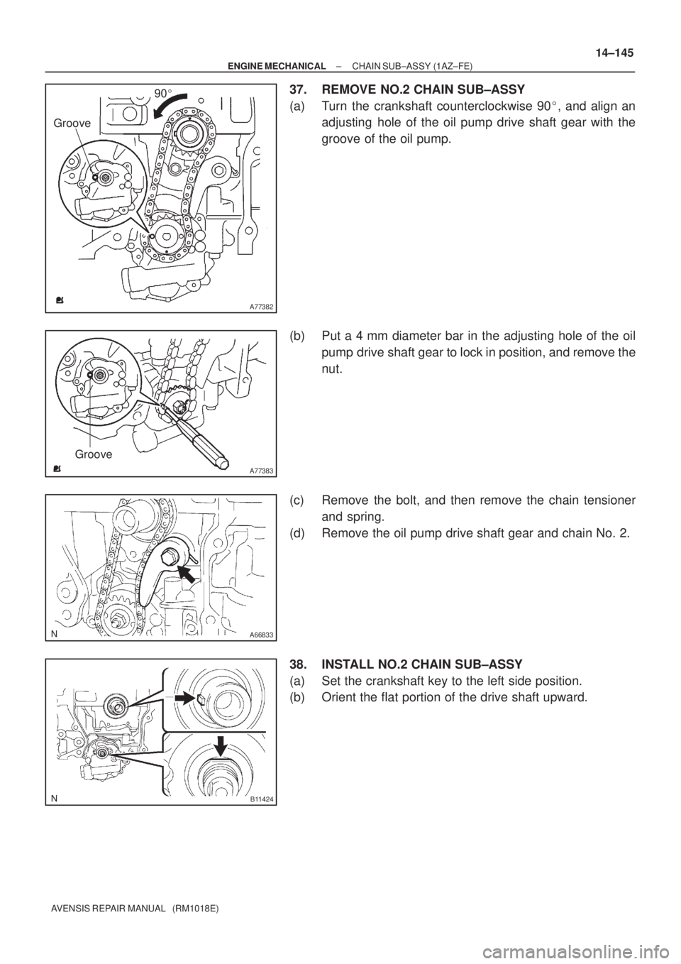
37. REMOVE NO.2 CHAIN SUB±ASSY
(a) Turn the crankshaft counterclockwise 90�, and align an
adjusting hole of the oil pump drive shaft gear with the
groove of the oil pump.
(b) Put a 4 mm diameter bar in the adjusting hole of the oil
pump drive shaft gear to lock in position, and remove the
nut.
(c) Remove the bolt, and then remove the chain tensioner
and spring.
(d) Remove the oil pump drive shaft gear and chain No. 2.
38. INSTALL NO.2 CHAIN SUB±ASSY
(a) Set the crankshaft key to the left side position.
(b) Orient the flat portion of the drive shaft upward.
Page 393 of 1690
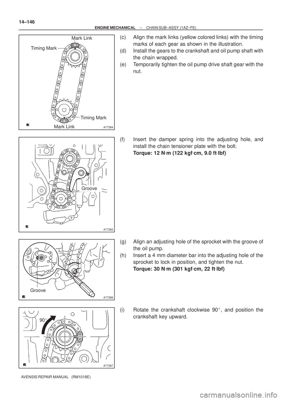
A77384
Mark Link
Timing Mark
Timing Mark
Mark Link
A77385
Groove
A77386
Groove
A77387
90� 14±146
± ENGINE MECHANICALCHAIN SUB±ASSY (1AZ±FE)
AVENSIS REPAIR MANUAL (RM1018E)
(c) Align the mark links (yellow colored links) with the timing
marks of each gear as shown in the illustration.
(d) Install the gears to the crankshaft and oil pump shaft with
the chain wrapped.
(e) Temporarily tighten the oil pump drive shaft gear with the
nut.
(f) Insert the damper spring into the adjusting hole, and
install the chain tensioner plate with the bolt.
Torque: 12 N�m (122 kgf�cm, 9.0 ft�lbf)
(g) Align an adjusting hole of the sprocket with the groove of
the oil pump.
(h) Insert a 4 mm diameter bar into the adjusting hole of the
sprocket to lock in position, and tighten the nut.
Torque: 30 N�m (301 kgf�cm, 22 ft�lbf)
(i) Rotate the crankshaft clockwise 90�, and position the
crankshaft key upward.
Page 394 of 1690
A77285
Unleaded Gasoline
Timing
Marks
Leaded Gasoline
Timing
Marks
Timing
Marks
Timing
Marks
A52505
A77388
SST
± ENGINE MECHANICALCHAIN SUB±ASSY (1AZ±FE)
14±147
AVENSIS REPAIR MANUAL (RM1018E)
39. INSTALL CRANKSHAFT TIMING GEAR OR SPROCKET
40. SET NO. 1 CYLINDER TO TDC/COMPRESSION
(a) Turn the camshafts with a wrench on the hexagonal lobe,
and align the timing marks of the camshaft timing gear
with each timing mark located on the No. 1 and No. 2
bearing caps as shown in the illustration.
(b) Using the crankshaft pulley bolt, turn the crankshaft and
position the key on the crankshaft upward.
41. INSTALL CHAIN VIBRATION DAMPER NO.1
42. INSTALL CHAIN SUB±ASSY
Page 406 of 1690
A77382
Groove90�
A77383
Groove
A66833
B11424
± ENGINE MECHANICALCHAIN SUB±ASSY (1AZ±FE)
14±145
AVENSIS REPAIR MANUAL (RM1018E)
37. REMOVE NO.2 CHAIN SUB±ASSY
(a) Turn the crankshaft counterclockwise 90�, and align an
adjusting hole of the oil pump drive shaft gear with the
groove of the oil pump.
(b) Put a 4 mm diameter bar in the adjusting hole of the oil
pump drive shaft gear to lock in position, and remove the
nut.
(c) Remove the bolt, and then remove the chain tensioner
and spring.
(d) Remove the oil pump drive shaft gear and chain No. 2.
38. INSTALL NO.2 CHAIN SUB±ASSY
(a) Set the crankshaft key to the left side position.
(b) Orient the flat portion of the drive shaft upward.
Page 407 of 1690
A77384
Mark Link
Timing Mark
Timing Mark
Mark Link
A77385
Groove
A77386
Groove
A77387
90� 14±146
± ENGINE MECHANICALCHAIN SUB±ASSY (1AZ±FE)
AVENSIS REPAIR MANUAL (RM1018E)
(c) Align the mark links (yellow colored links) with the timing
marks of each gear as shown in the illustration.
(d) Install the gears to the crankshaft and oil pump shaft with
the chain wrapped.
(e) Temporarily tighten the oil pump drive shaft gear with the
nut.
(f) Insert the damper spring into the adjusting hole, and
install the chain tensioner plate with the bolt.
Torque: 12 N�m (122 kgf�cm, 9.0 ft�lbf)
(g) Align an adjusting hole of the sprocket with the groove of
the oil pump.
(h) Insert a 4 mm diameter bar into the adjusting hole of the
sprocket to lock in position, and tighten the nut.
Torque: 30 N�m (301 kgf�cm, 22 ft�lbf)
(i) Rotate the crankshaft clockwise 90�, and position the
crankshaft key upward.


14±147
AVENSIS REPAIR MANUAL (RM1018")