Page 207 of 1690

34. FULLY TIGHTEN UPPER CONTROL ARM ASSY
(a) Fully tighten the bolt.
Torque: 74 N �m (755 kgf �")
±
DRIVE SHAFT / PROPELLER SHAFT REAR AXLE CARRIER SUB±ASSY LH
30±35
AVENSIS REPAIR MANUAL (RM1018E)
34. FULLY TIGHTEN UPPER CONTROL ARM ASSY
(a) Fully tighten the bolt.
Torque: 74 N �m (755 kgf �cm, 55 ft �lbf)
NOTICE:
When installing the bolt, hold the nut not to rotate.
35. FULLY TIGHTEN REAR SUSPENSION ARM ASSY NO.1 LH
(a) Fully tighten the nut (ball joint side). Torque: 105 N �m (1,071 kgf �cm, 77 ft �lbf)
(b) Install the clip.
NOTICE:
If the holes for the clip are not aligned, tighten the nut up to 60 � further.
(c) Fully tighten the bolt and nut.
Torque: 74 N �m (755 kgf �cm, 55 ft �lbf)
NOTICE:
When installing the bolt, hold the nut not to rotate.
36. FULLY TIGHTEN LOWER CONTROL ARM ASSY LH
(a) Fully tighten the nut. Torque: 60 N �m (612 kgf �cm, 44 ft �lbf)
(b) Install the clip.
NOTICE:
If the holes for the clip are not aligned, tighten the nut up to 60 � further.
(c) Fully tighten the bolt (member side). Torque: 105 N �m (1,071 kgf �cm, 77 ft �lbf)
NOTICE:
When installing the bolt, hold the nut not to rotate.
37.INSPECT AND ADJUST PARKING BRAKE LEVER TRAVEL (See page 33±2)
38.INSPECT AND ADJUST REAR WHEEL ALIGNMENT (See page 27±4)
39. CHECK ABS SPEED SENSOR SIGNAL
(a)ABD WITH EBD SYSTEM (See page 05±699)
(b)ABD WITH EBD & BA & TRC & VSC SYSTEM ( See page 05±756)
Page 208 of 1690

REAR AXLE LH HUB BOLT
REPLACEMENT")
300K0±01
������F45577
Hold
Turn
SST
������F45578
Hold
Turn
Nut
Washer
30±36
±
DRIVE SHAFT / PROPELLER SHAFT REAR AXLE LH HUB BOLT
AVENSIS REPAIR MANUAL (RM1018E)
REAR AXLE LH HUB BOLT
REPLACEMENT
HINT:
�COMPONENTS: See page 30±30
�Replace the RH side by the same procedures as the LH side.
1. REMOVE REAR WHEEL
2. SEPARATE REAR DISC BRAKE CALIPER ASSY LH
(a) Removing the 2 bolts and rear disc brake caliper assy.
NOTICE:
Use a string or other device to keep the brake caliper from hanging down\
.
3. REMOVE REAR DISC
4. REMOVE REAR AXLE LH HUB BOLT
(a) Turn the axle hub to move the LH hub bolt and SST, thatare to be removed, to the place shown in the illustration.
NOTICE:
Do not replace the hub bolt in any places other than that in
the illustration.
(b) Using SST and a hammer handle or an equivalent to hold the axle hub, remove the LH hub bolt.
SST 09628±10011
5. INSTALL REAR AXLE LH HUB BOLT
(a) Install a washer and nut to a new LH hub bolt as shown in the illustration.
(b) Using a hammer handle or an equivalent to hold the axle
hub, install the LH hub bolt by torquing the nut.
6. INSTALL REAR DISC
7. INSTALL REAR DISC BRAKE CALIPER ASSY LH
(a) Install the rear disc brake caliper assy with the 2 bolts. Torque: 47 N �m (475 kgf �cm, 34 ft �lbf)
8. INSTALL REAR WHEEL Torque: 103 N �m (1,050 kgf �cm, 76 ft �lbf)
Page 228 of 1690
100FM±02
A78489
A78490
10±66
± ENGINE CONTROL SYSTEMACCELERATOR PEDAL ASSY (1AZ±FSE/1CD±FTV)
AVENSIS REPAIR MANUAL (RM1018E)
ACCELERATOR PEDAL ASSY (1AZ±FSE/1CD±FTV)
REPLACEMENT
1. REMOVE ACCELERATOR PEDAL
(a) Using a clip remover, remove the clip.
(b) Open the floor carpet.
(c) Disconnect the accelerator position sensor connector.
(d) Remove the 2 bolts, and then remove the accelerator
pedal.
2. INSTALL ACCELERATOR PEDAL
Torque: 5.4 N�m (55 kgf�cm, 48 in.�lbf)
Page 229 of 1690
100FP±01
A79139
A79141
± ENGINE CONTROL SYSTEMCAMSHAFT POSITION SENSOR (1CD±FTV)
10±63
AVENSIS REPAIR MANUAL (RM1018E)
CAMSHAFT POSITION SENSOR (1CD±FTV)
REPLACEMENT
1. SEPARATE RETURN TUBE SUB±ASSY
(a) Remove the bolt and separate the return tube sub±assy.
2. REMOVE CAMSHAFT POSITION SENSOR
(a) Remove the bolt and disconnect the wire harness.
(b) Disconnect the connector, remove the bolt and the cam-
shaft position sensor.
3. INSTALL CAMSHAFT POSITION SENSOR
Torque:
8.8 N�m (90 kgf�cm, 79 in.�lbf) for camshaft position sensor
5.0 N�m (51 kgf�cm, 44 in.�lbf) for wire harness
4. INSTALL RETURN TUBE SUB±ASSY
Torque: 9.0 N�m (92 kgf�cm, 80 in.�lbf)
Page 230 of 1690
100FQ±01
A79142
10±64
± ENGINE CONTROL SYSTEMCRANKSHAFT POSITION SENSOR (1CD±FTV)
AVENSIS REPAIR MANUAL (RM1018E)
CRANKSHAFT POSITION SENSOR (1CD±FTV)
REPLACEMENT
1. REMOVE ENGINE UNDER COVER RH
2. REMOVE CRANKSHAFT POSITION SENSOR
(a) Disconnect the connector, remove the bolt and the crank-
shaft position sensor.
3. INSTALL CRANKSHAFT POSITION SENSOR
Torque: 8.8 N�m (90 kgf�cm, 78 in.�lbf)
Page 237 of 1690
100FR±01
A79186
±
ENGINE CONTROL SYSTEM ECM
10±65
AVENSIS REPAIR MANUAL (RM1018E)
ECM
REPLACEMENT
HINT:
1CD±FTV Engine Type:
Each injector assembly has a characteristic fuel injecting behavior. The ECM stores compensation codes
which are used to optimize fuel injection for the injectors. When replacing t\
he ECM, the compensation codes
must be set to the new ECM.
1.REMOVE GLOVE COMPARTMENT DOOR ASSY (See page 71±11)
2.REMOVE ECM
(a)Disconnect the 4 ECM connectors (1ZZ±FE, 3ZZ±FE,1AZ±FE, 1CD±FTV).
(b)Disconnect the 5 ECM connectors (1AZ±FSE).
(c)Disconnect the wire harness clamp.
(d)Remove the bolt and screw, then remove the ECM.
(e)Remove the 2 screws and the ECM bracket No. 1 from the ECM.
(f)Remove the 2 screws and the ECM bracket No. 2 from the ECM.
3.INSTALL ECM Torque: 5.5 N �m (56 kgf �cm, 49 in. �lbf)
4.INSTALL GLOVE COMPARTMENT DOOR ASSY (See page 71±11)
5.REGISTRATION OF INJECTOR COMPENSATION CODE (1CD±FTV ENGINE TYPE) (See page 05±528)
Page 238 of 1690
100FN±01
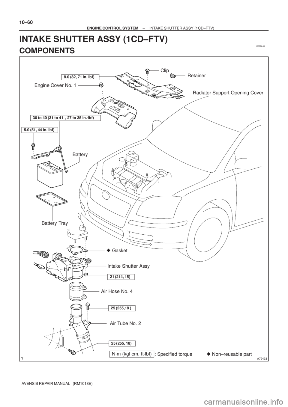
A79433N´m (kgf´cm, ft´lbf)
: Specified torque� Non±reusable part � Gasket
25 (255, 18)
25 (255,18 )
21 (214, 15)
30 to 40 (31 to 41 , 27 to 35 in.�lbf)
5.0 (51, 44 in.�lbf)
8.0 (82, 71 in.�lbf)
Radiator Support Opening Cover Engine Cover No. 1
Battery
Battery Tray
Intake Shutter Assy
Air Hose No. 4
Clip
Retainer
Air Tube No. 2
10±60
± ENGINE CONTROL SYSTEMINTAKE SHUTTER ASSY (1CD±FTV)
AVENSIS REPAIR MANUAL (RM1018E)
INTAKE SHUTTER ASSY (1CD±FTV)
COMPONENTS
Page 239 of 1690
100FO±01
A80092
B08171
A64328
2 to 7 mm0 to 4 mm
± ENGINE CONTROL SYSTEMINTAKE SHUTTER ASSY (1CD±FTV)
10±61
AVENSIS REPAIR MANUAL (RM1018E)
Removal & Installation and Disassembly & Reassembly
1. REMOVE RADIATOR SUPPORT OPENING COVER
2. REMOVE ENGINE COVER NO.1
(a) Remove the 5 nuts and the engine cover.
3. REMOVE BATTERY
4. REMOVE AIR HOSE NO.4
(a) Loosen the 2 hose clamps.
(b) Remove the 2 bolts and separate the air tube No. 2.
(c) Remove the air hose No. 4.
5. REMOVE INTAKE SHUTTER ASSY
(a) Disconnect the 2 connectors.
(b) Remove the 3 nuts, then remove the intake shutter and
the gasket.
6. INSTALL INTAKE SHUTTER ASSY
(a) Install a new gasket and the intake shutter with the 3 nuts.
Torque: 21 N�m (214 kgf�cm, 15 ft�lbf)
7. INSTALL AIR HOSE NO.4
(a) Install the air hose No. 4 to the air tube No. 2.
(b) Install the air tube No. 2 with the 2 bolts.
Torque: 25 N�m (255 kgf�cm, 18 ft�lbf)
(c) Install the air hose and hose clamp as shown in the il-
lustration.

AVENSIS REPAIR MANUAL (RM1018E)
ACCELERATOR PEDAL ASSY (1AZ±FSE/1CD±FTV)
REPLACEMENT
1. REMOVE ACC")

10±63
AVENSIS REPAIR MANUAL (RM1018E)
CAMSHAFT POSITION SENSOR (1CD±FTV)
REPLACEMENT
1. SEPARATE RETURN TUBE SUB")

AVENSIS REPAIR MANUAL (RM1018E)
CRANKSHAFT POSITION SENSOR (1CD±FTV)
REPLACEMENT
1. REMOVE ENGINE UNDER COVER R")

ECM
REPLACEMENT
HINT:
1CD±FTV Engine Type:
Each injector assembly has a characteristic fuel injecting behavior.")

10±61
AVENSIS REPAIR MANUAL (RM1018E)
Removal & Installation and Disassembly & Reassembly
1.")