Page 456 of 1767
7 CHECK MASS AIR FLOW SENSOR
1. Reconnect harness connectors disconnected.
2. Start engine and warm it up to normal operating temperature.
3. Check voltage between ECM terminal 35 (Mass air flow sensor signal) and ground.
SEF400Y
4. If the voltage is out of specification, disconnect MAFS harness connector and connect it again.
Then repeat above check.
OK or NG
OKEGO TO 8.
NGEReplace mass air flow sensor.
8 CHECK INTERMITTENT INCIDENT
Refer to ªTROUBLE DIAGNOSIS FOR INTERMITTENT INCIDENTº, EC-78.
EINSPECTION END
DTC 0102 MASS AIR FLOW SENZD30DDTi
Diagnostic Procedure (Cont'd)
EC-94
Page 505 of 1767
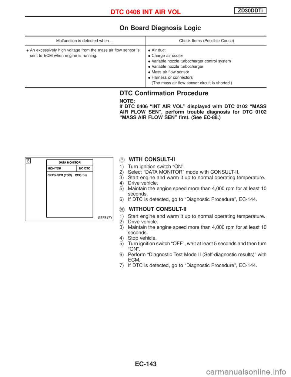
On Board Diagnosis Logic
Malfunction is detected when ... Check Items (Possible Cause)
IAn excessively high voltage from the mass air flow sensor is
sent to ECM when engine is running.IAir duct
ICharge air cooler
IVariable nozzle turbocharger control system
IVariable nozzle turbocharger
IMass air flow sensor
IHarness or connectors
(The mass air flow sensor circuit is shorted.)
DTC Confirmation Procedure
NOTE:
If DTC 0406 ªINT AIR VOLº displayed with DTC 0102 ªMASS
AIR FLOW SENº, perform trouble diagnosis for DTC 0102
ªMASS AIR FLOW SENº first. (See EC-88.)
WITH CONSULT-II
1) Turn ignition switch ªONº.
2) Select ªDATA MONITORº mode with CONSULT-II.
3) Start engine and warm it up to normal operating temperature.
4) Drive vehicle.
5) Maintain the engine speed more than 4,000 rpm for at least 10
seconds.
6) If DTC is detected, go to ªDiagnostic Procedureº, EC-144.
WITHOUT CONSULT-II
1) Start engine and warm it up to normal operating temperature.
2) Drive vehicle.
3) Maintain the engine speed more than 4,000 rpm for at least 10
seconds.
4) Stop vehicle.
5) Turn ignition switch ªOFFº, wait at least 5 seconds and then turn
ªONº.
6) Perform ªDiagnostic Test Mode II (Self-diagnostic results)º with
ECM.
7) If DTC is detected, go to ªDiagnostic Procedureº, EC-144.SEF817Y
DTC 0406 INT AIR VOLZD30DDTi
EC-143
Page 506 of 1767
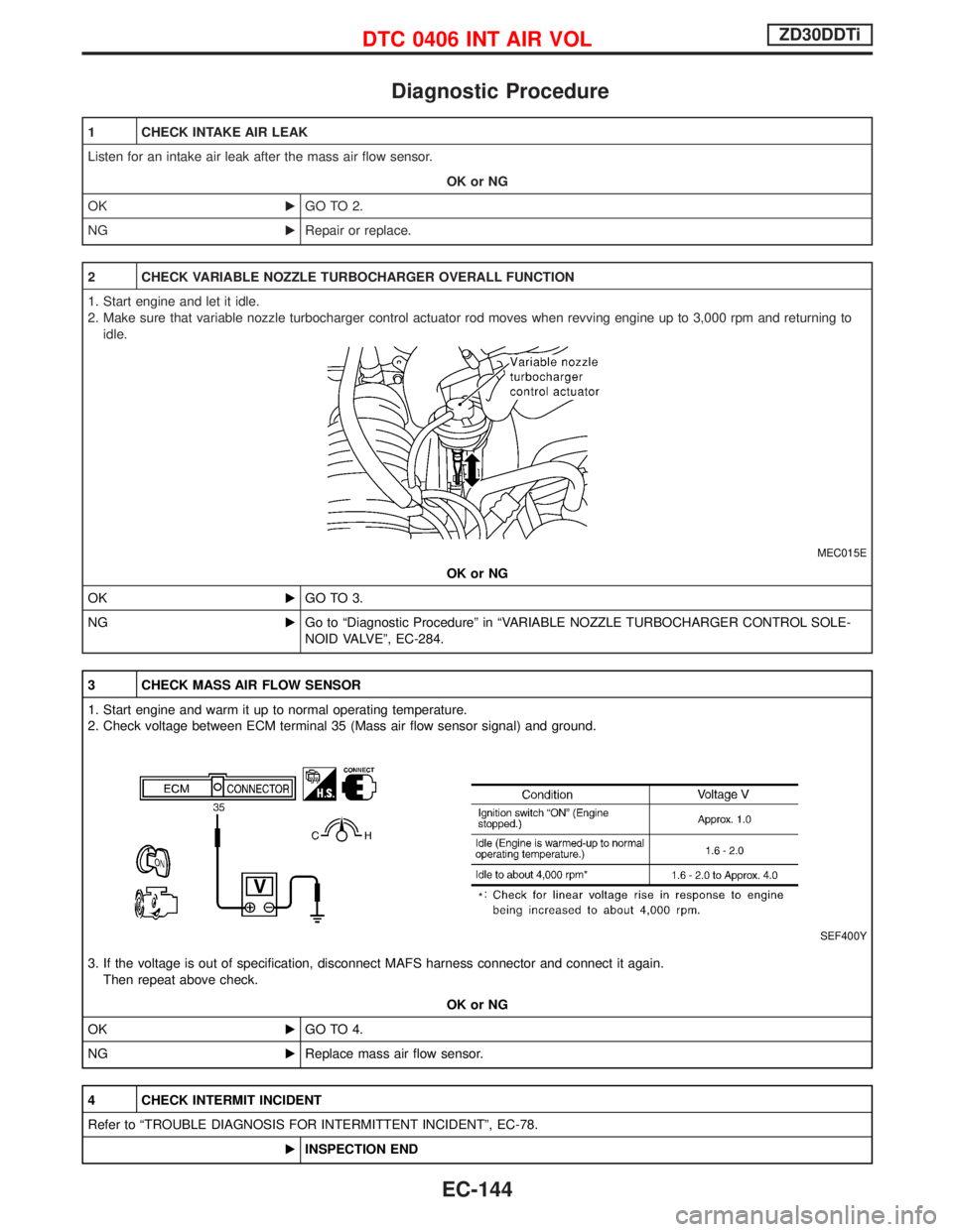
Diagnostic Procedure
1 CHECK INTAKE AIR LEAK
Listen for an intake air leak after the mass air flow sensor.
OK or NG
OKEGO TO 2.
NGERepair or replace.
2 CHECK VARIABLE NOZZLE TURBOCHARGER OVERALL FUNCTION
1. Start engine and let it idle.
2. Make sure that variable nozzle turbocharger control actuator rod moves when revving engine up to 3,000 rpm and returning to
idle.
MEC015E
OK or NG
OKEGO TO 3.
NGEGo to ªDiagnostic Procedureº in ªVARIABLE NOZZLE TURBOCHARGER CONTROL SOLE-
NOID VALVEº, EC-284.
3 CHECK MASS AIR FLOW SENSOR
1. Start engine and warm it up to normal operating temperature.
2. Check voltage between ECM terminal 35 (Mass air flow sensor signal) and ground.
SEF400Y
3. If the voltage is out of specification, disconnect MAFS harness connector and connect it again.
Then repeat above check.
OK or NG
OKEGO TO 4.
NGEReplace mass air flow sensor.
4 CHECK INTERMIT INCIDENT
Refer to ªTROUBLE DIAGNOSIS FOR INTERMITTENT INCIDENTº, EC-78.
EINSPECTION END
DTC 0406 INT AIR VOLZD30DDTi
EC-144
Page 584 of 1767
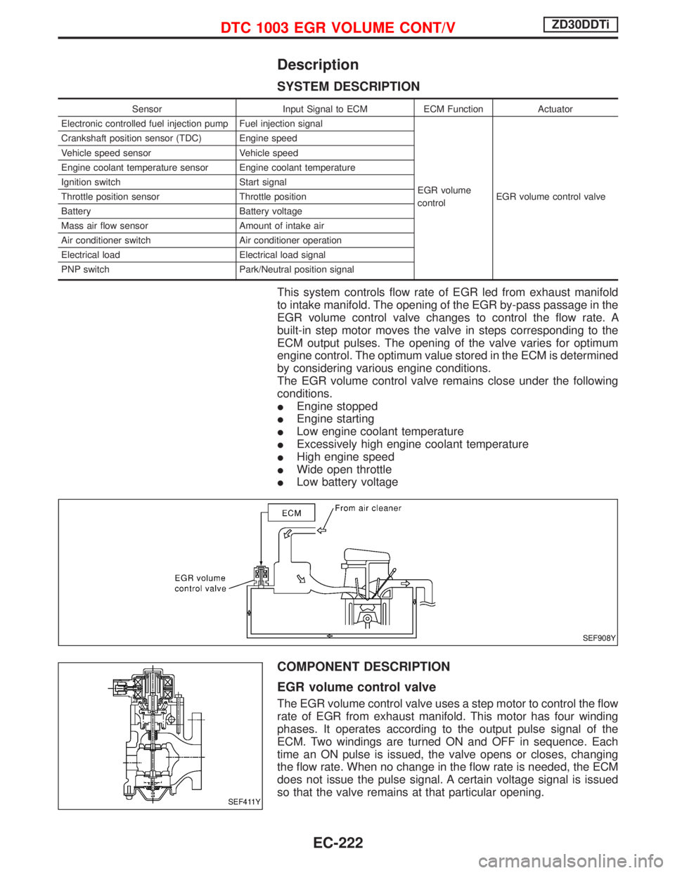
Description
SYSTEM DESCRIPTION
Sensor Input Signal to ECM ECM Function Actuator
Electronic controlled fuel injection pump Fuel injection signal
EGR volume
controlEGR volume control valve Crankshaft position sensor (TDC) Engine speed
Vehicle speed sensor Vehicle speed
Engine coolant temperature sensor Engine coolant temperature
Ignition switch Start signal
Throttle position sensor Throttle position
Battery Battery voltage
Mass air flow sensor Amount of intake air
Air conditioner switch Air conditioner operation
Electrical load Electrical load signal
PNP switch Park/Neutral position signal
This system controls flow rate of EGR led from exhaust manifold
to intake manifold. The opening of the EGR by-pass passage in the
EGR volume control valve changes to control the flow rate. A
built-in step motor moves the valve in steps corresponding to the
ECM output pulses. The opening of the valve varies for optimum
engine control. The optimum value stored in the ECM is determined
by considering various engine conditions.
The EGR volume control valve remains close under the following
conditions.
IEngine stopped
IEngine starting
ILow engine coolant temperature
IExcessively high engine coolant temperature
IHigh engine speed
IWide open throttle
ILow battery voltage
COMPONENT DESCRIPTION
EGR volume control valve
The EGR volume control valve uses a step motor to control the flow
rate of EGR from exhaust manifold. This motor has four winding
phases. It operates according to the output pulse signal of the
ECM. Two windings are turned ON and OFF in sequence. Each
time an ON pulse is issued, the valve opens or closes, changing
the flow rate. When no change in the flow rate is needed, the ECM
does not issue the pulse signal. A certain voltage signal is issued
so that the valve remains at that particular opening.
SEF908Y
SEF411Y
DTC 1003 EGR VOLUME CONT/VZD30DDTi
EC-222
Page 625 of 1767
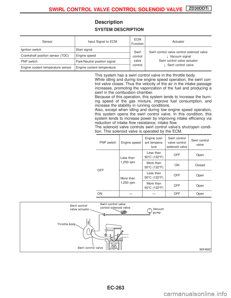
Description
SYSTEM DESCRIPTION
Sensor Input Signal to ECMECM
FunctionActuator
Ignition switch Start signal
Swirl
control
valve
controlSwirl control valve control solenoid valve
"Vacuum signal
Swirl control valve actuator
"Swirl control valve Crankshaft position sensor (TDC) Engine speed
PNP switch Park/Neutral position signal
Engine coolant temperature sensor Engine coolant temperature
This system has a swirl control valve in the throttle body.
While idling and during low engine speed operation, the swirl con-
trol valve closes. Thus the velocity of the air in the intake passage
increases, promoting the vaporization of the fuel and producing a
swirl in the combustion chamber.
Because of this operation, this system tends to increase the burn-
ing speed of the gas mixture, improve fuel consumption, and
increase the stability in running conditions.
Also, except when idling and during low engine speed operation,
this system opens the swirl control valve. In this condition, this
system tends to increase power by improving intake efficiency via
reduction of intake flow resistance, intake flow.
The solenoid valve controls swirl control valve's shut/open condi-
tion. This solenoid valve is operated by the ECM.
PNP switch Engine speedEngine cool-
ant tempera-
tureSwirl control
valve control
solenoid valveSwirl control
valve
OFFLess than
1,250 rpmLess than
50ÉC (122ÉF)OFF Open
More than
50ÉC (122ÉF)ON Closed
More than
1,250 rpmLess than
50ÉC (122ÉF)OFF Open
More than
50ÉC (122ÉF)OFF Open
ON Ð Ð OFF Open
SEF452Z
SWIRL CONTROL VALVE CONTROL SOLENOID VALVEZD30DDTi
EC-263
Page 655 of 1767
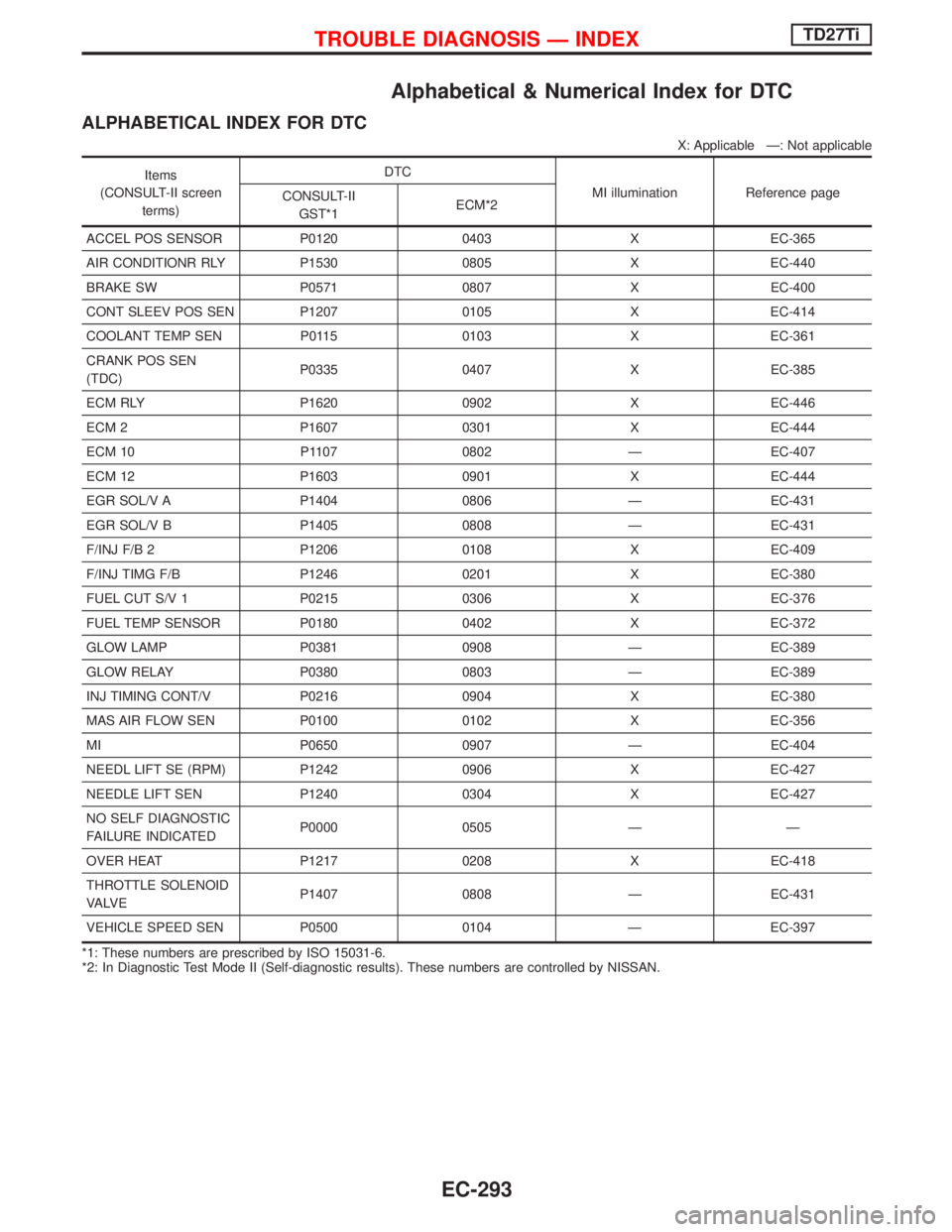
Alphabetical & Numerical Index for DTC
ALPHABETICAL INDEX FOR DTC
X: Applicable Ð: Not applicable
Items
(CONSULT-II screen
terms)DTC
MI illumination Reference page
CONSULT-II
GST*1ECM*2
ACCEL POS SENSOR P0120 0403 X EC-365
AIR CONDITIONR RLY P1530 0805 X EC-440
BRAKE SW P0571 0807 X EC-400
CONT SLEEV POS SEN P1207 0105 X EC-414
COOLANT TEMP SEN P0115 0103 X EC-361
CRANK POS SEN
(TDC)P0335 0407 X EC-385
ECM RLY P1620 0902 X EC-446
ECM 2 P1607 0301 X EC-444
ECM 10 P1107 0802 Ð EC-407
ECM 12 P1603 0901 X EC-444
EGR SOL/V A P1404 0806 Ð EC-431
EGR SOL/V B P1405 0808 Ð EC-431
F/INJ F/B 2 P1206 0108 X EC-409
F/INJ TIMG F/B P1246 0201 X EC-380
FUEL CUT S/V 1 P0215 0306 X EC-376
FUEL TEMP SENSOR P0180 0402 X EC-372
GLOW LAMP P0381 0908 Ð EC-389
GLOW RELAY P0380 0803 Ð EC-389
INJ TIMING CONT/V P0216 0904 X EC-380
MAS AIR FLOW SEN P0100 0102 X EC-356
MI P0650 0907 Ð EC-404
NEEDL LIFT SE (RPM) P1242 0906 X EC-427
NEEDLE LIFT SEN P1240 0304 X EC-427
NO SELF DIAGNOSTIC
FAILURE INDICATEDP0000 0505 Ð Ð
OVER HEAT P1217 0208 X EC-418
THROTTLE SOLENOID
VA LV EP1407 0808 Ð EC-431
VEHICLE SPEED SEN P0500 0104 Ð EC-397
*1: These numbers are prescribed by ISO 15031-6.
*2: In Diagnostic Test Mode II (Self-diagnostic results). These numbers are controlled by NISSAN.
TROUBLE DIAGNOSIS Ð INDEXTD27Ti
EC-293
Page 656 of 1767
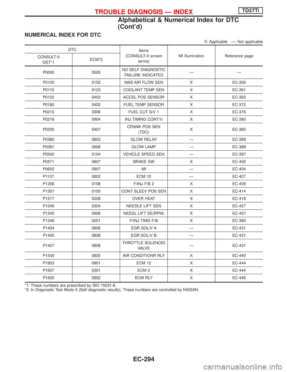
NUMERICAL INDEX FOR DTC
X: Applicable Ð: Not applicable
DTC
Items
(CONSULT-II screen
terms)MI illumination Reference page
CONSULT-II
GST*1ECM*2
P0000 0505NO SELF DIAGNOSTIC
FAILURE INDICATEDÐÐ
P0100 0102 MAS AIR FLOW SEN X EC-356
P0115 0103 COOLANT TEMP SEN X EC-361
P0120 0403 ACCEL POS SENSOR X EC-365
P0180 0402 FUEL TEMP SENSOR X EC-372
P0215 0306 FUEL CUT S/V 1 X EC-376
P0216 0904 INJ TIMING CONT/V X EC-380
P0335 0407CRANK POS SEN
(TDC)X EC-385
P0380 0803 GLOW RELAY Ð EC-389
P0381 0908 GLOW LAMP Ð EC-389
P0500 0104 VEHICLE SPEED SEN Ð EC-397
P0571 0807 BRAKE SW X EC-400
P0650 0907 MI Ð EC-404
P1107 0802 ECM 10 Ð EC-407
P1206 0108 F/INJ F/B 2 X EC-409
P1207 0105 CONT SLEEV POS SEN X EC-414
P1217 0208 OVER HEAT X EC-418
P1240 0304 NEEDLE LIFT SEN X EC-427
P1242 0906 NEEDL LIFT SE(RPM) X EC-427
P1246 0201 F/INJ TIMG F/B X EC-380
P1404 0806 EGR SOL/V A Ð EC-431
P1405 0808 EGR SOL/V B Ð EC-431
P1407 0808THROTTLE SOLENOID
VA LV EÐ EC-431
P1530 0805 AIR CONDITIONR RLY X EC-440
P1603 0901 ECM 12 X EC-444
P1607 0301 ECM 2 X EC-444
P1620 0902 ECM RLY X EC-446
*1: These numbers are prescribed by ISO 15031-6.
*2: In Diagnostic Test Mode II (Self-diagnostic results). These numbers are controlled by NISSAN.
TROUBLE DIAGNOSIS Ð INDEXTD27Ti
Alphabetical & Numerical Index for DTC
(Cont'd)
EC-294
Page 667 of 1767
System Chart
Crankshaft position sensor
(TDC)E
ECM
Control sleeve position sensorE
Fuel temperature sensorE
Mass air flow sensorE
Engine coolant temperature sen-
sorE
Needle lift sensorE
Accelerator position sensorE
Accelerator position switchE
Air conditioner switchE
Ignition switchE
Battery voltageE
Vehicle speed sensorE
Brake switchE
Atmospheric pressure sensor
(inside ECM)E
EFuel injection controlEElectric governor
EFuel injection timing controlEInjection timing control valve
EFuel cut controlEFuel cut solenoid valve
EGlow control systemEGlow relay & glow lamp
EOn board diagnostic systemEMalfunction indicator lamp
(On the instrument panel)
EEGR valve & Throttle control
valve controlEEGRC-solenoid valve A, B and
throttle control solenoid valve
(models for Germany)
EAir conditioning cut controlEAir conditioner relay
ENGINE AND EMISSION CONTROL OVERALL SYSTEMTD27Ti
EC-305